Open HardwareAssembly Instructions
Guides for installation and assembly of the LulzBot line of products made by FAME 3D LLC.
Guides for installation and assembly of the LulzBot line of products made by FAME 3D LLC.
WARNING:
At Aleph Objects, Inc. we respect your freedom to modify your LulzBot™ 3D printer. Any modifications or attempted repairs that cause damage are not covered under the Warranty.
Questions? Contact Technical Support by emailing Support@LulzBot.com, or by calling +1-970-377-1111.
Power down and unplug your 3D printer.

Release the connector(s) for your tool head that are located above the large herringbone gear.
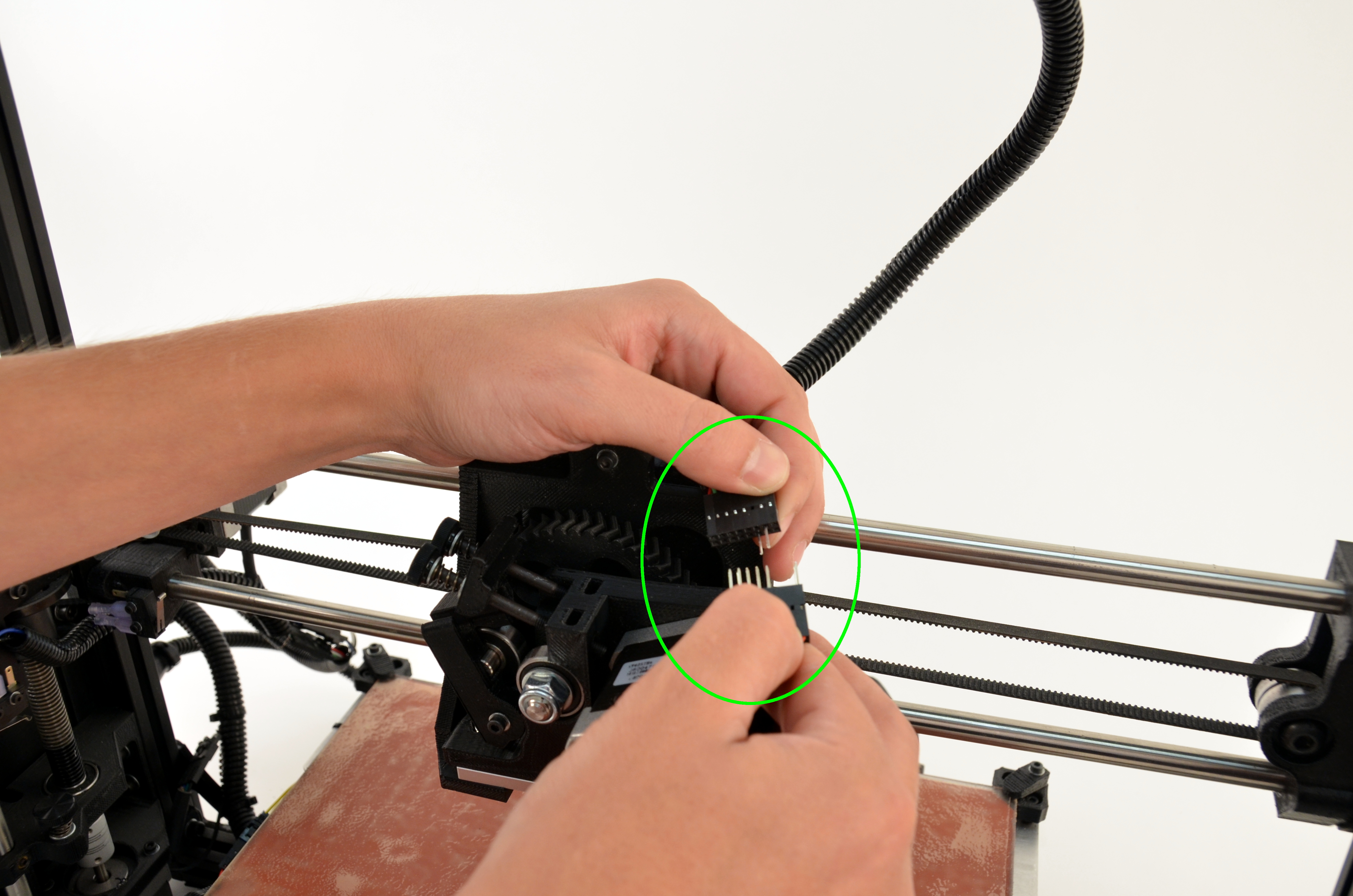
Be careful not to let the tool head fall onto your build plate.
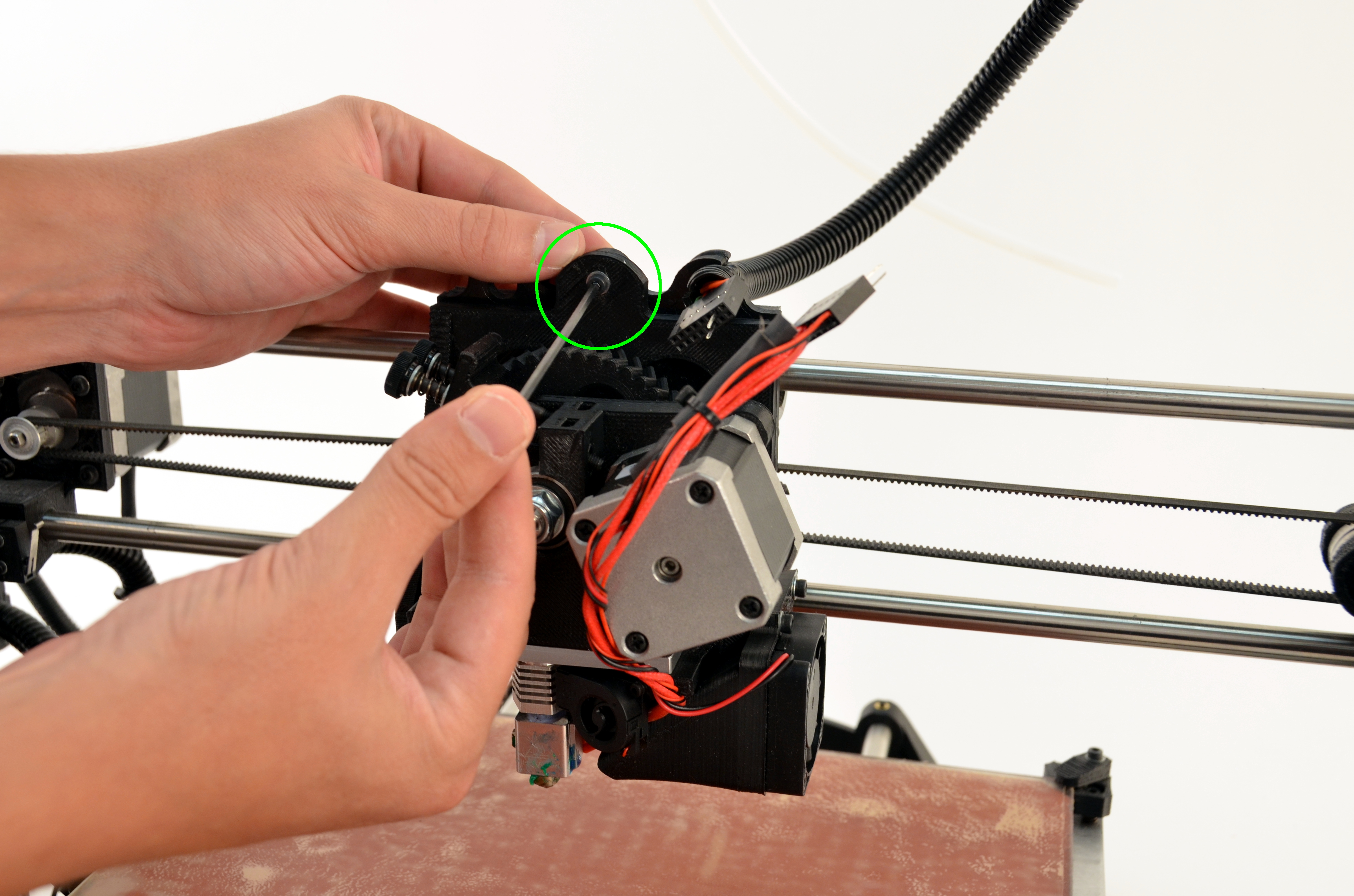
Using your 2.5mm driver remove the single screw holding your tool head to the printer.
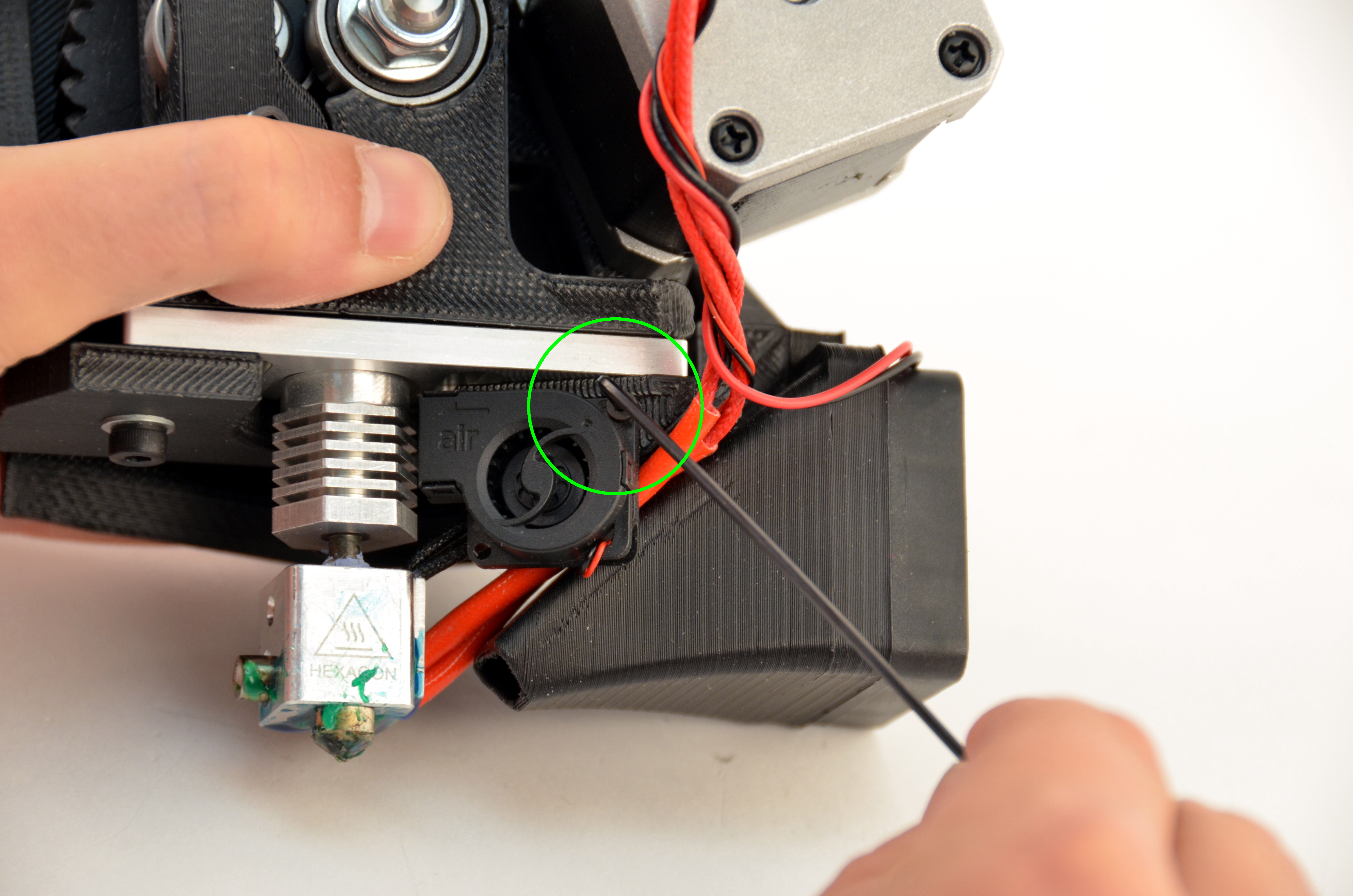
Remove the screw holding the micro blower in place using your 1.5mm driver, and set the screw aside.
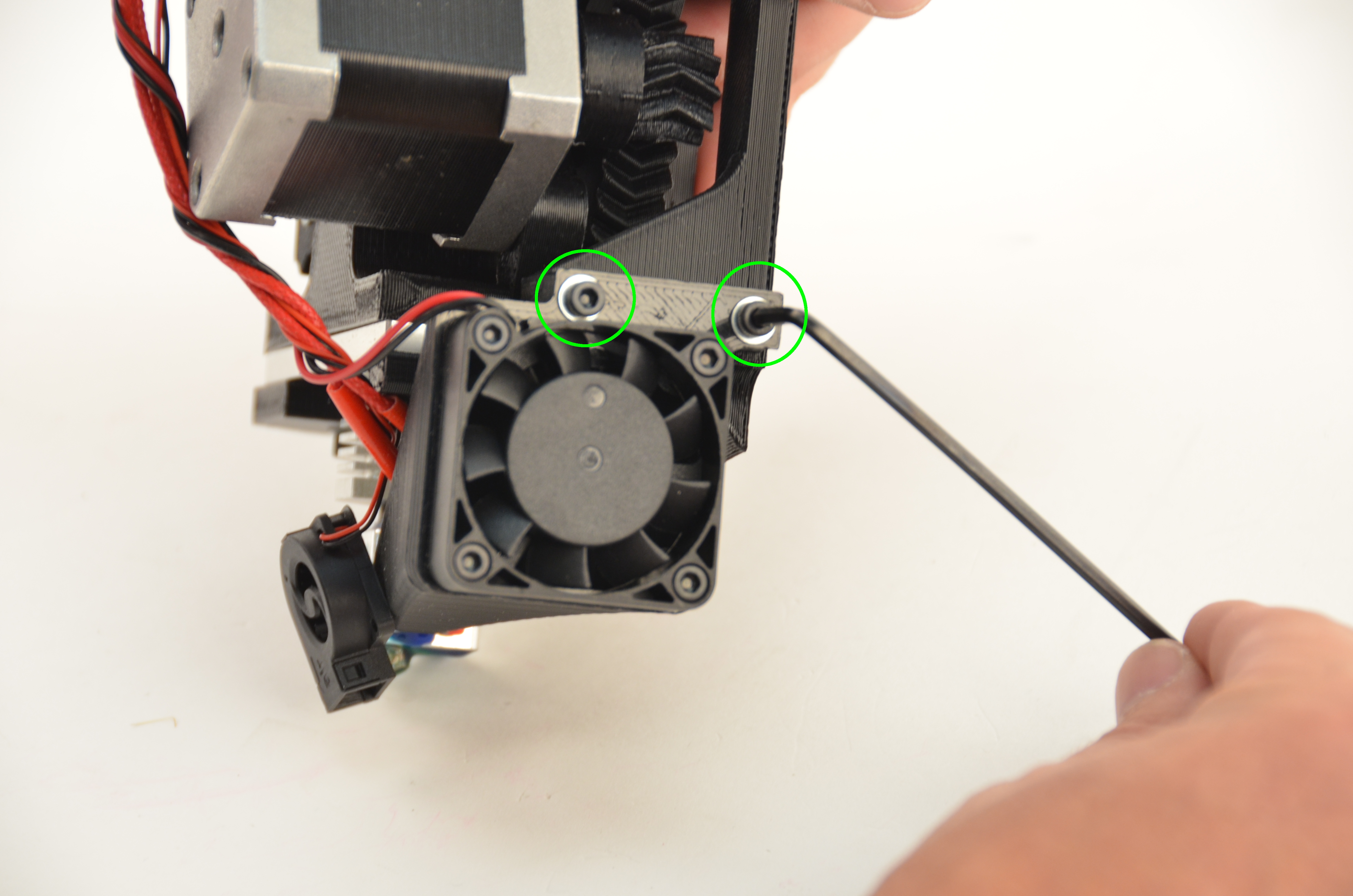
Using your 2.5mm driver, remove the two screws holding the fan mount to the tool head.
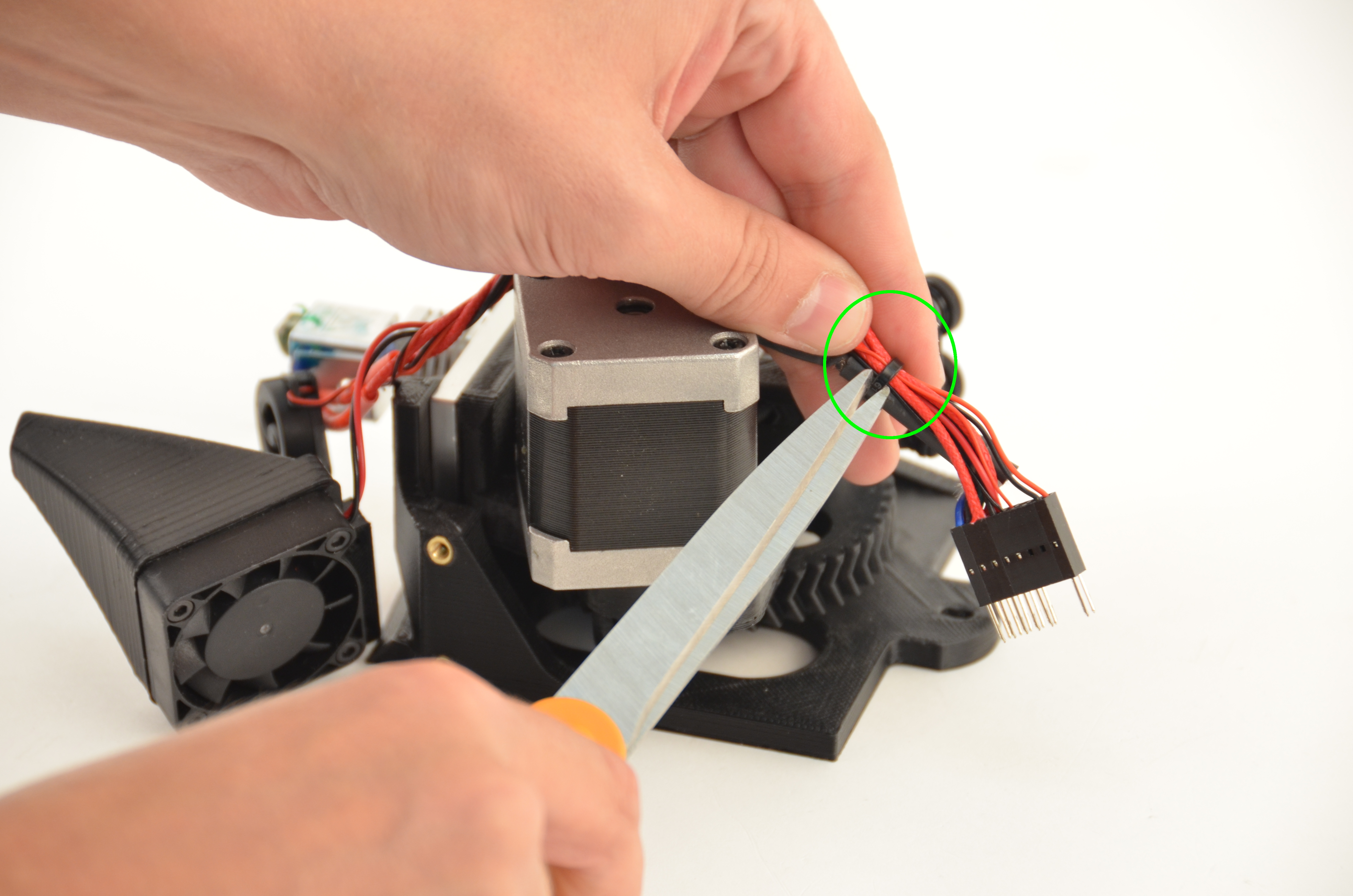
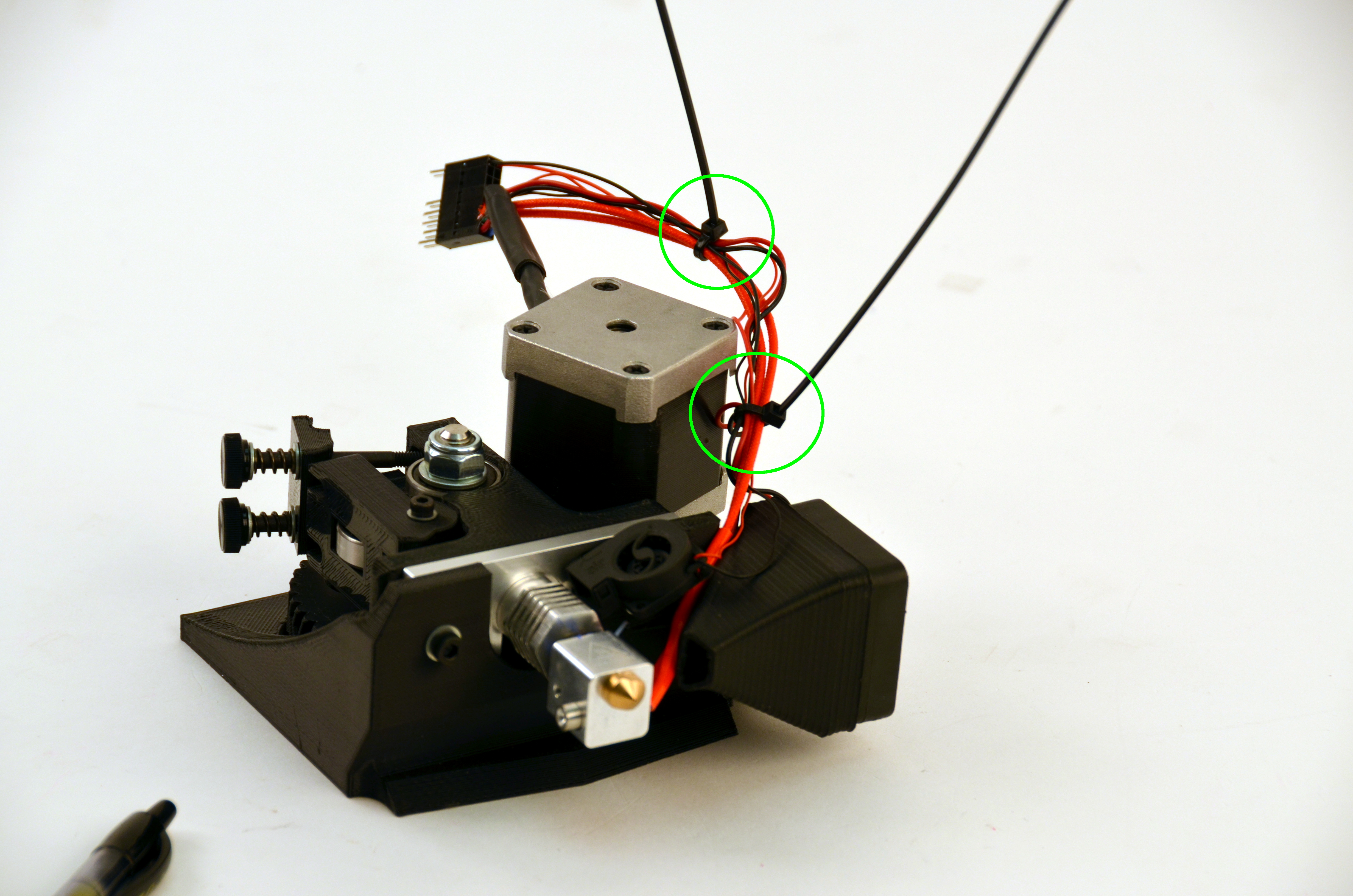
Cut the zip ties holding the wiring bundle for the toolhead harness.
Be careful not to cut any of the wires.
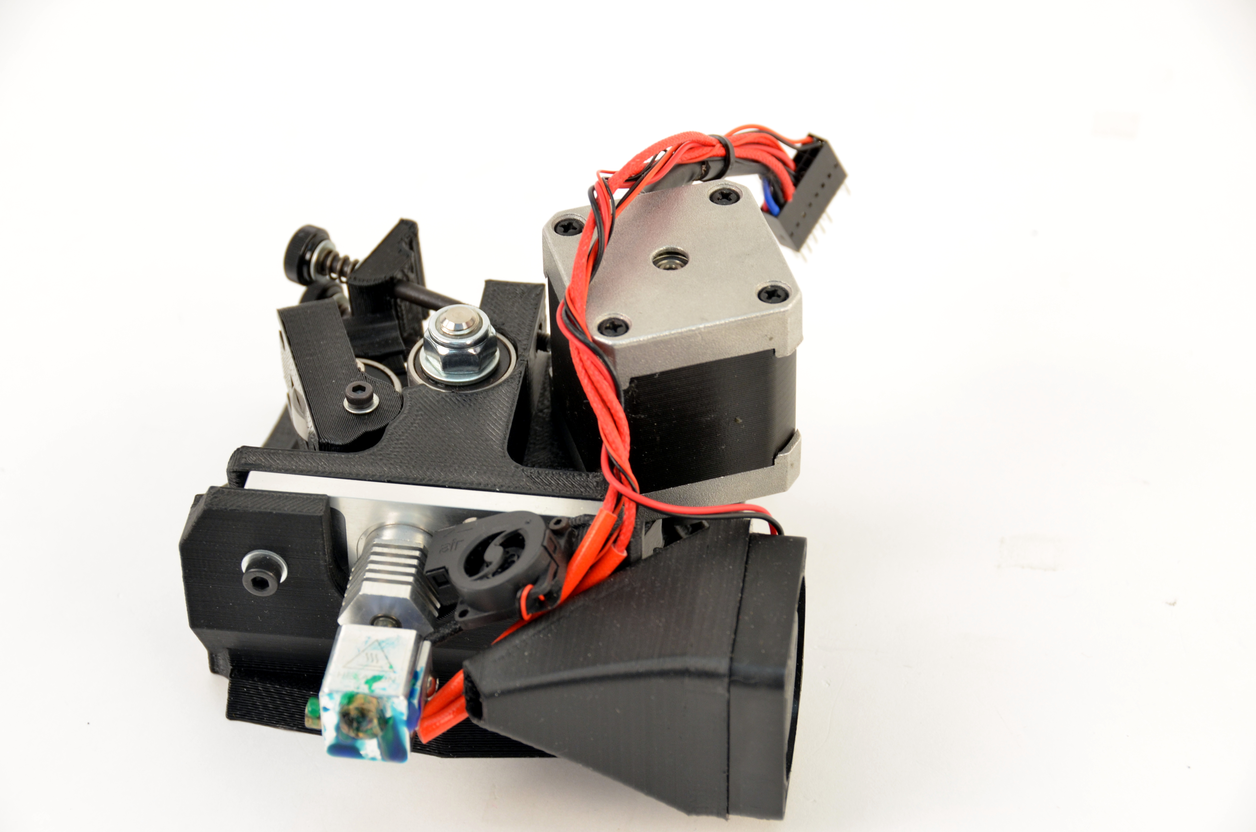
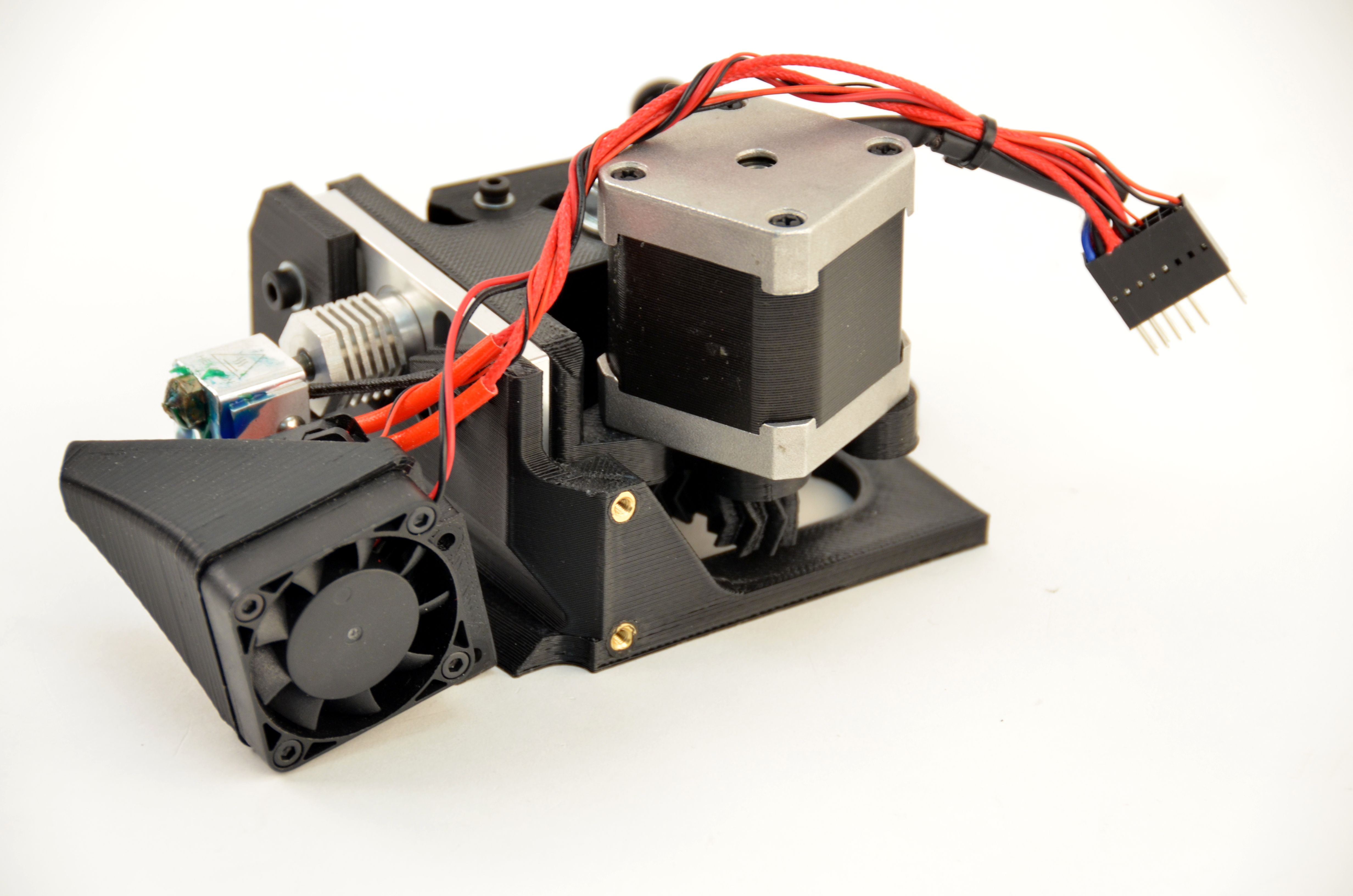
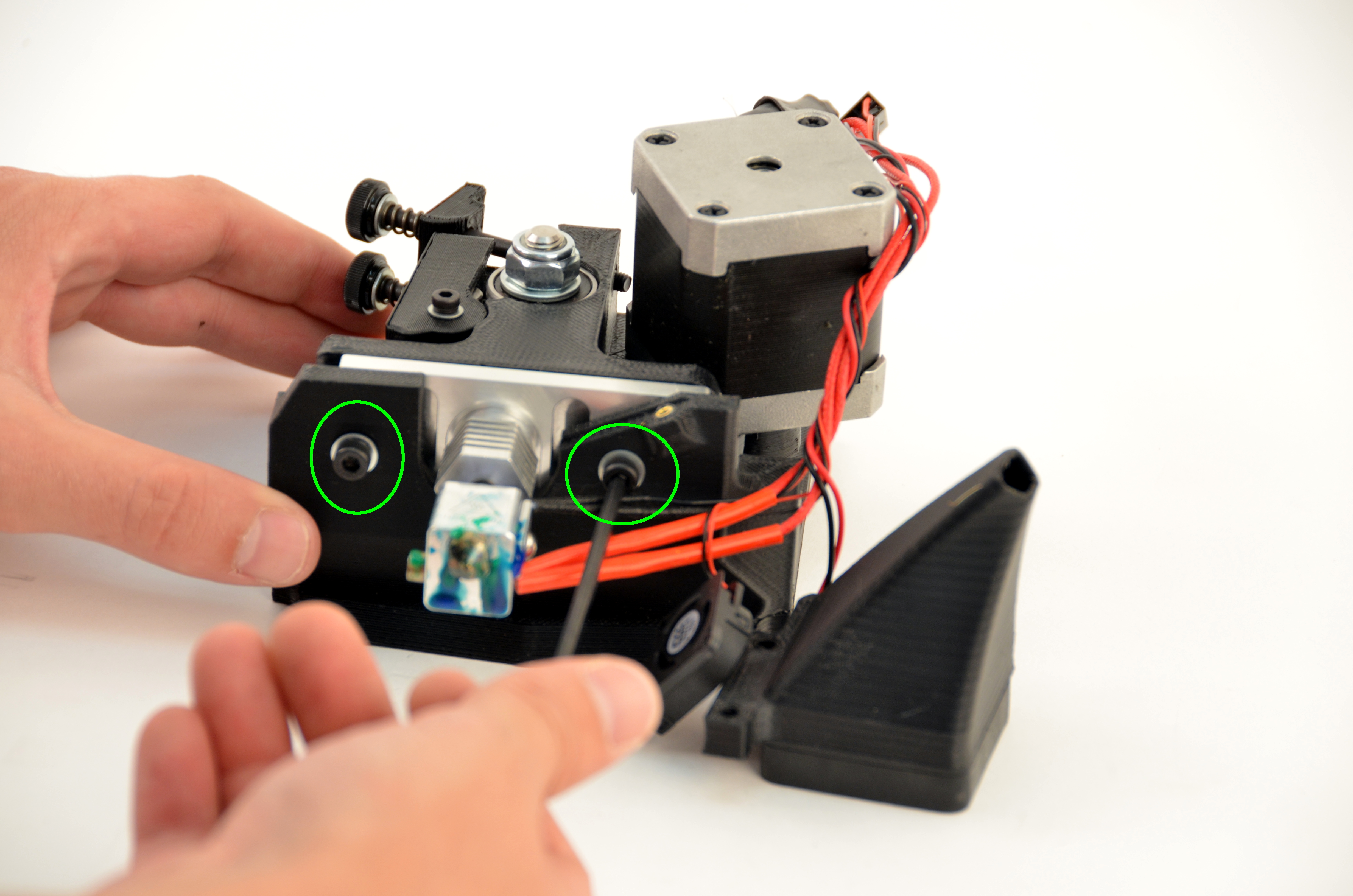
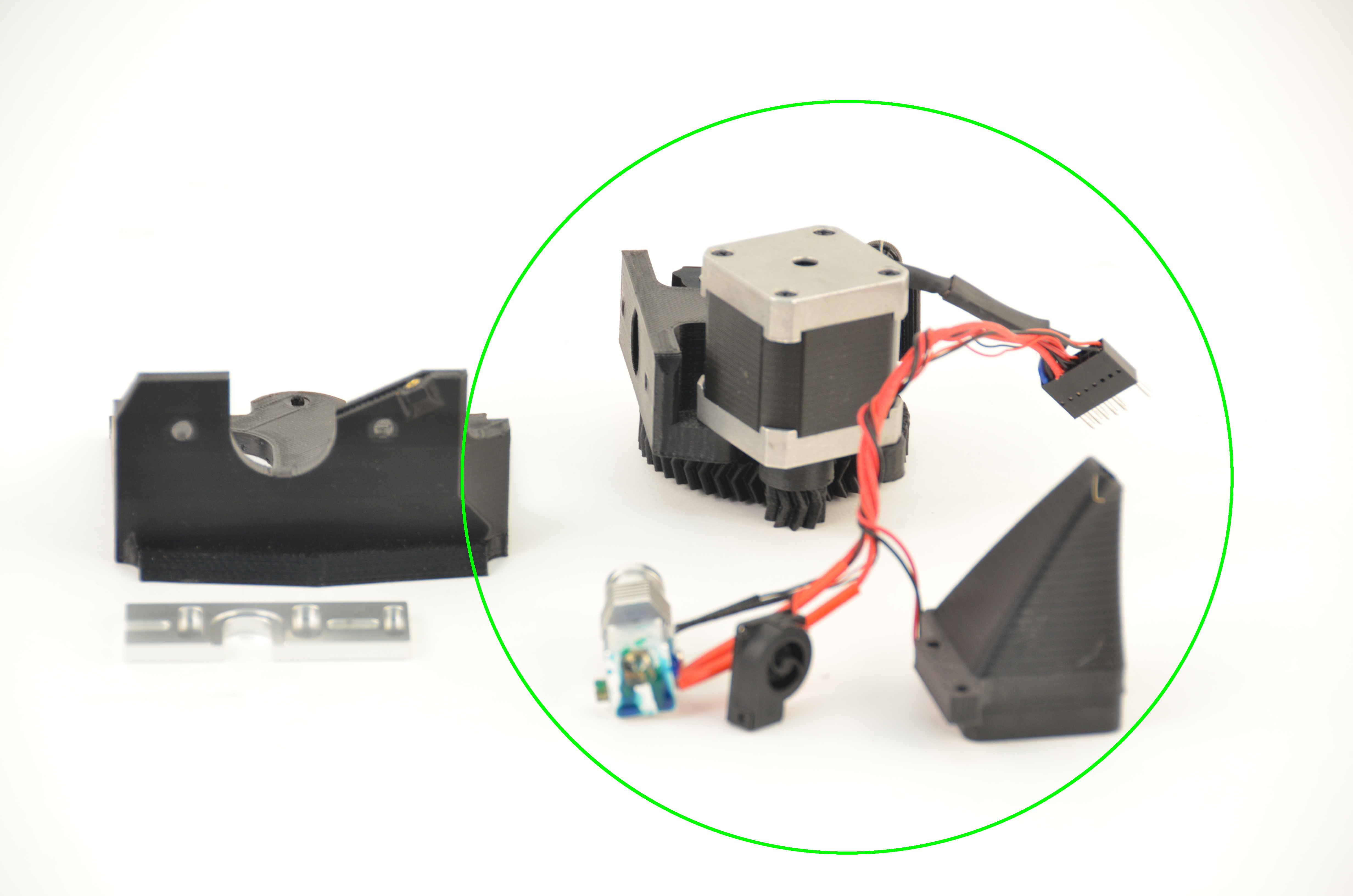
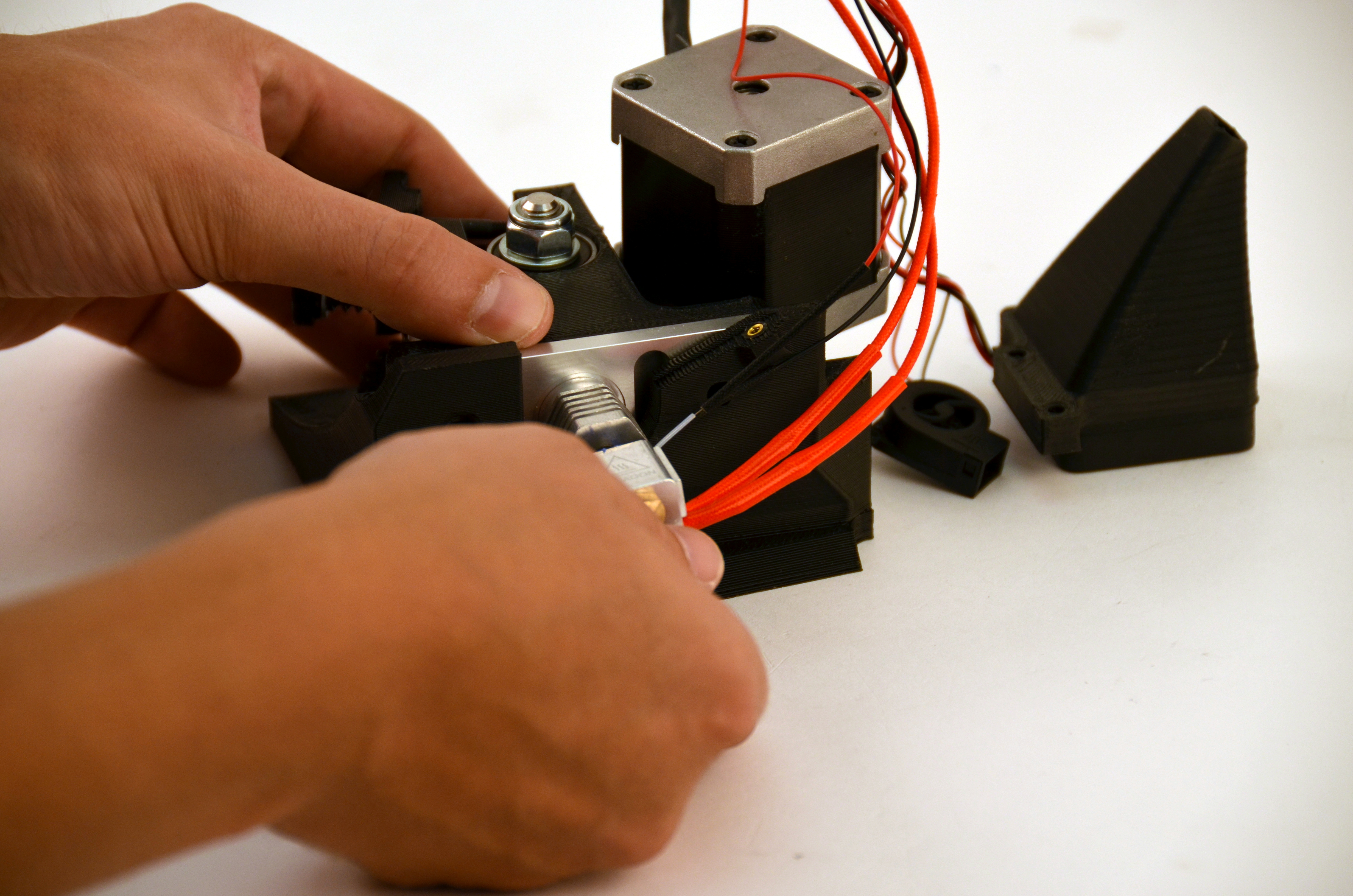
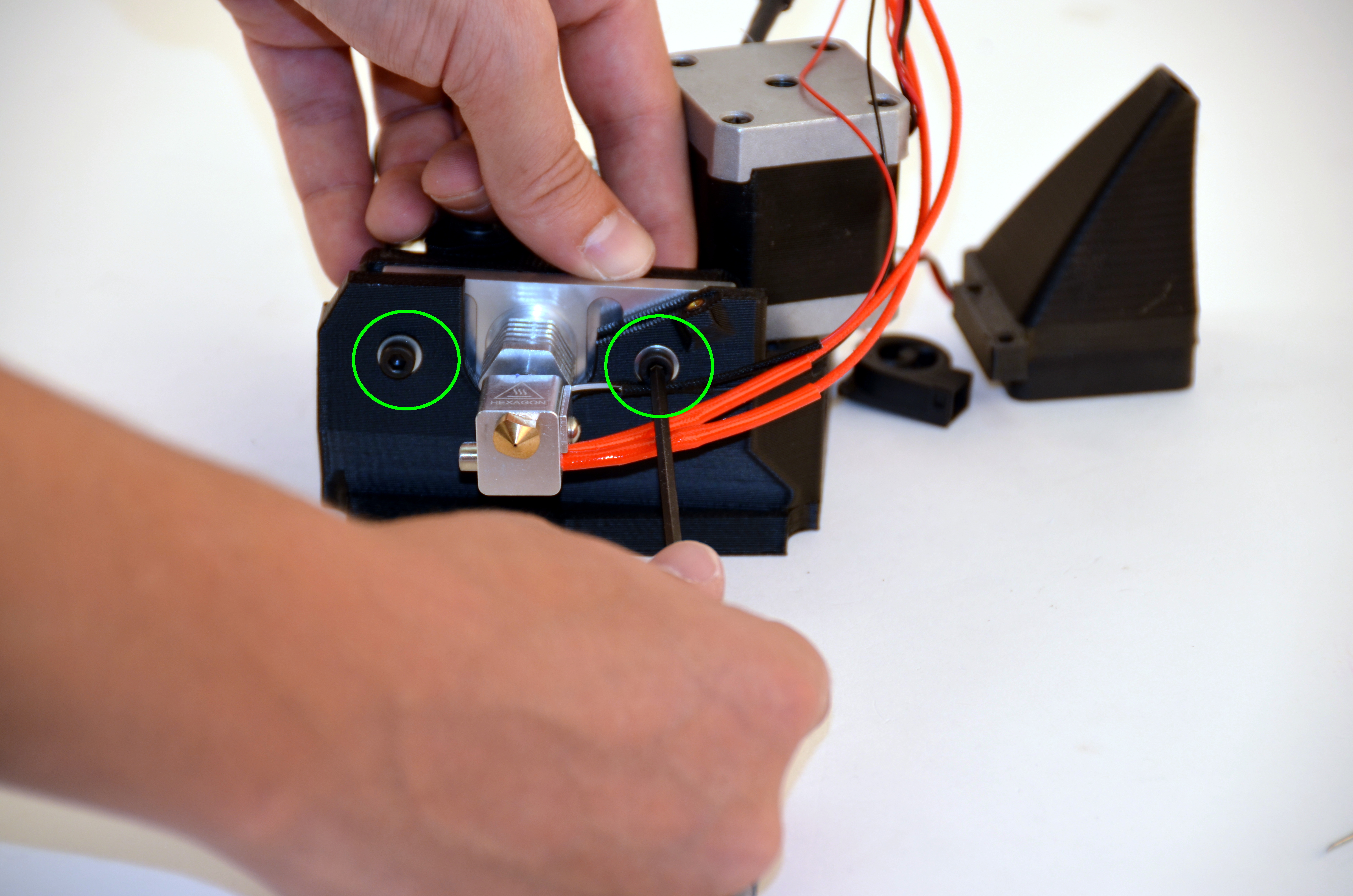
Remove the two screws holding the extruder and hot end to the tool head mounting plate using your 3mm driver.
Gently remove the too head mount and aluminum plate.
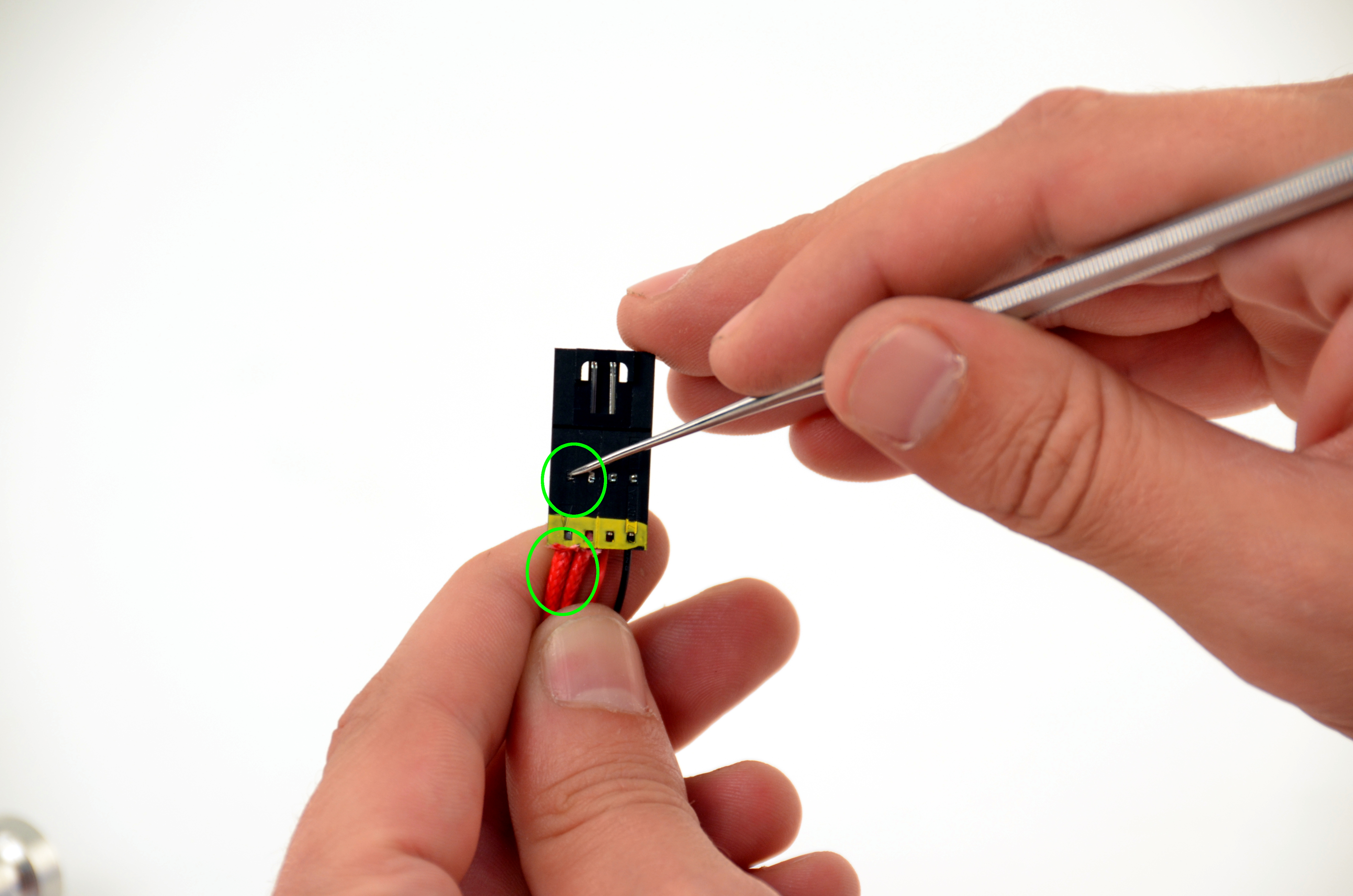
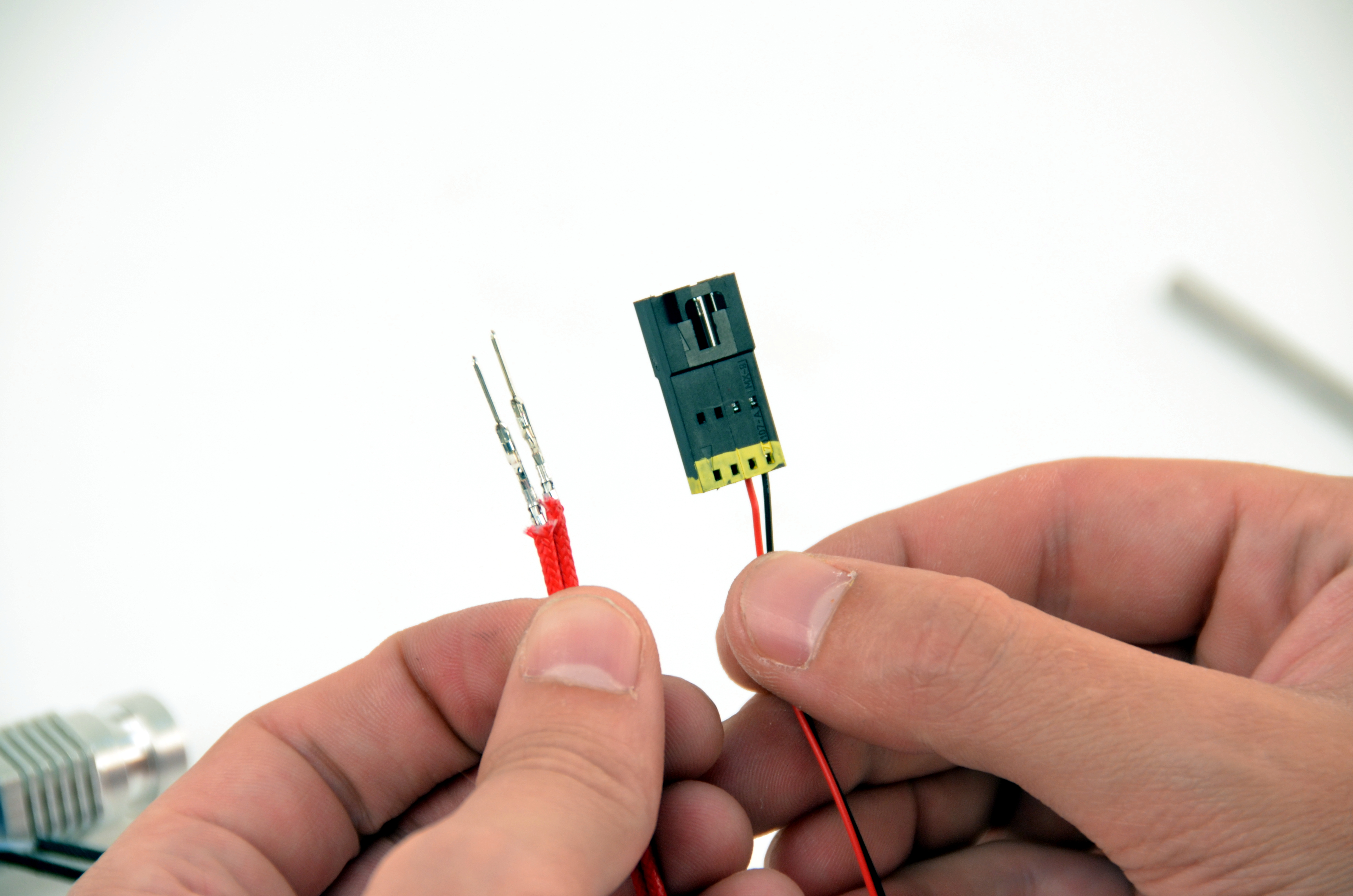
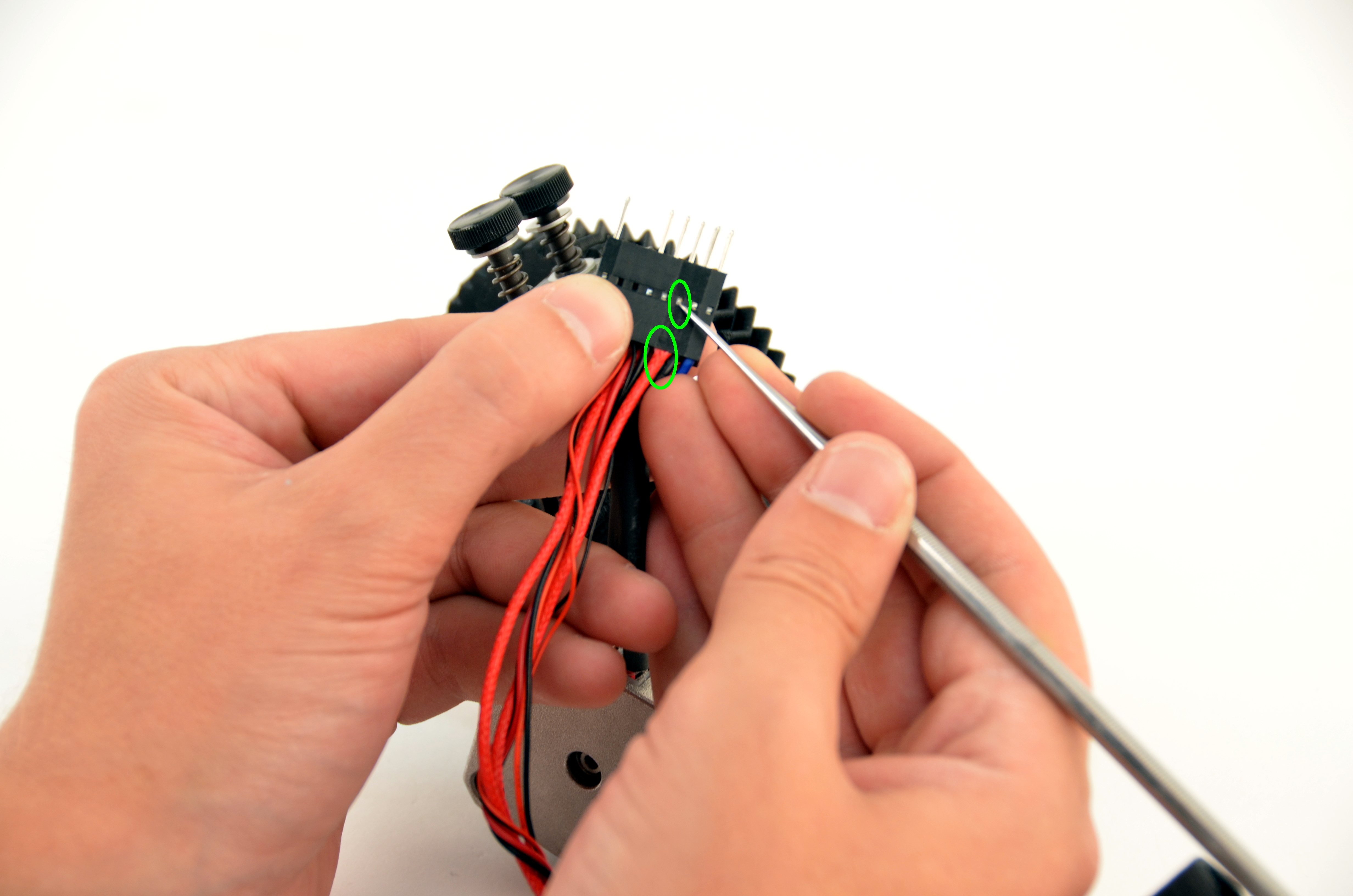
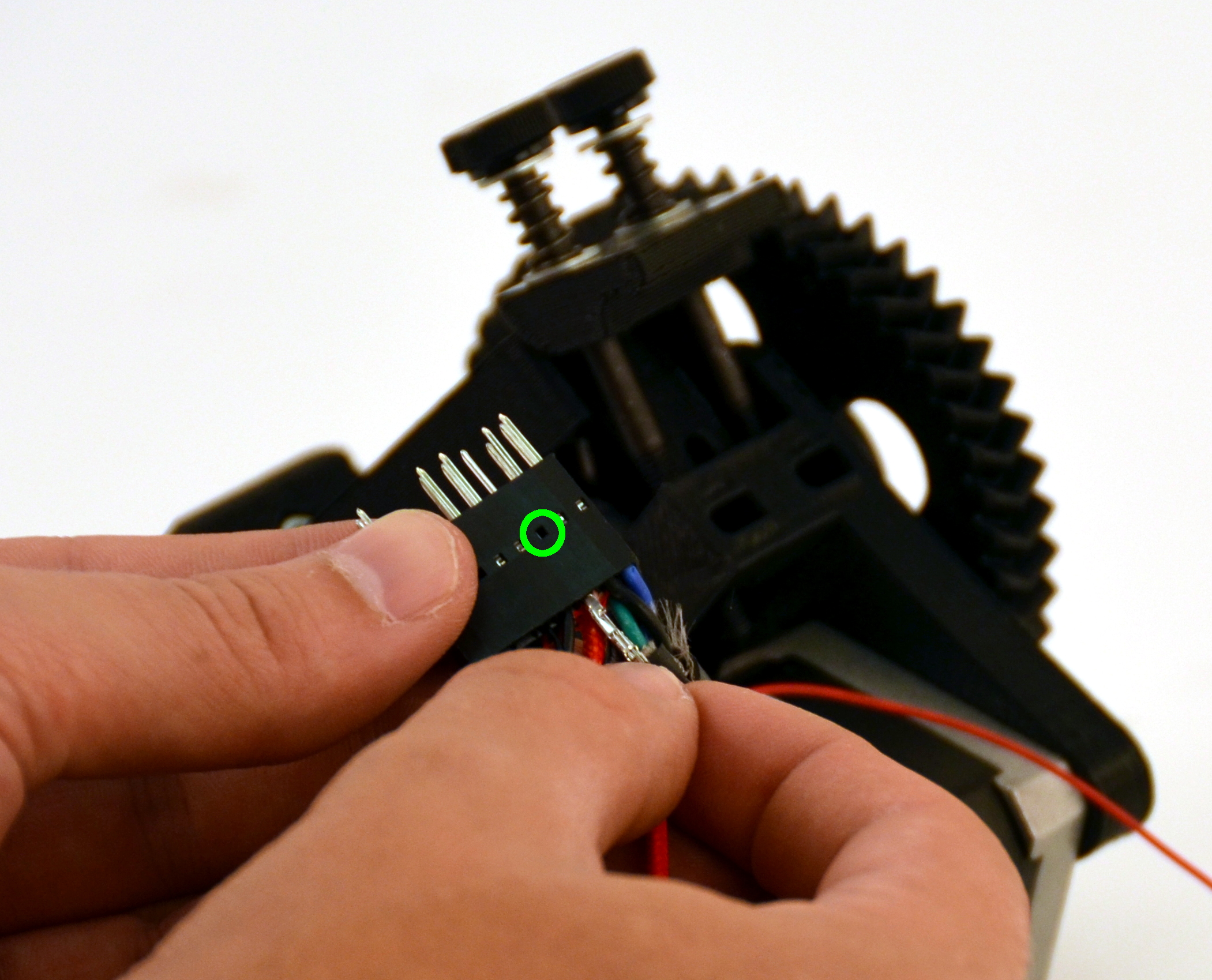
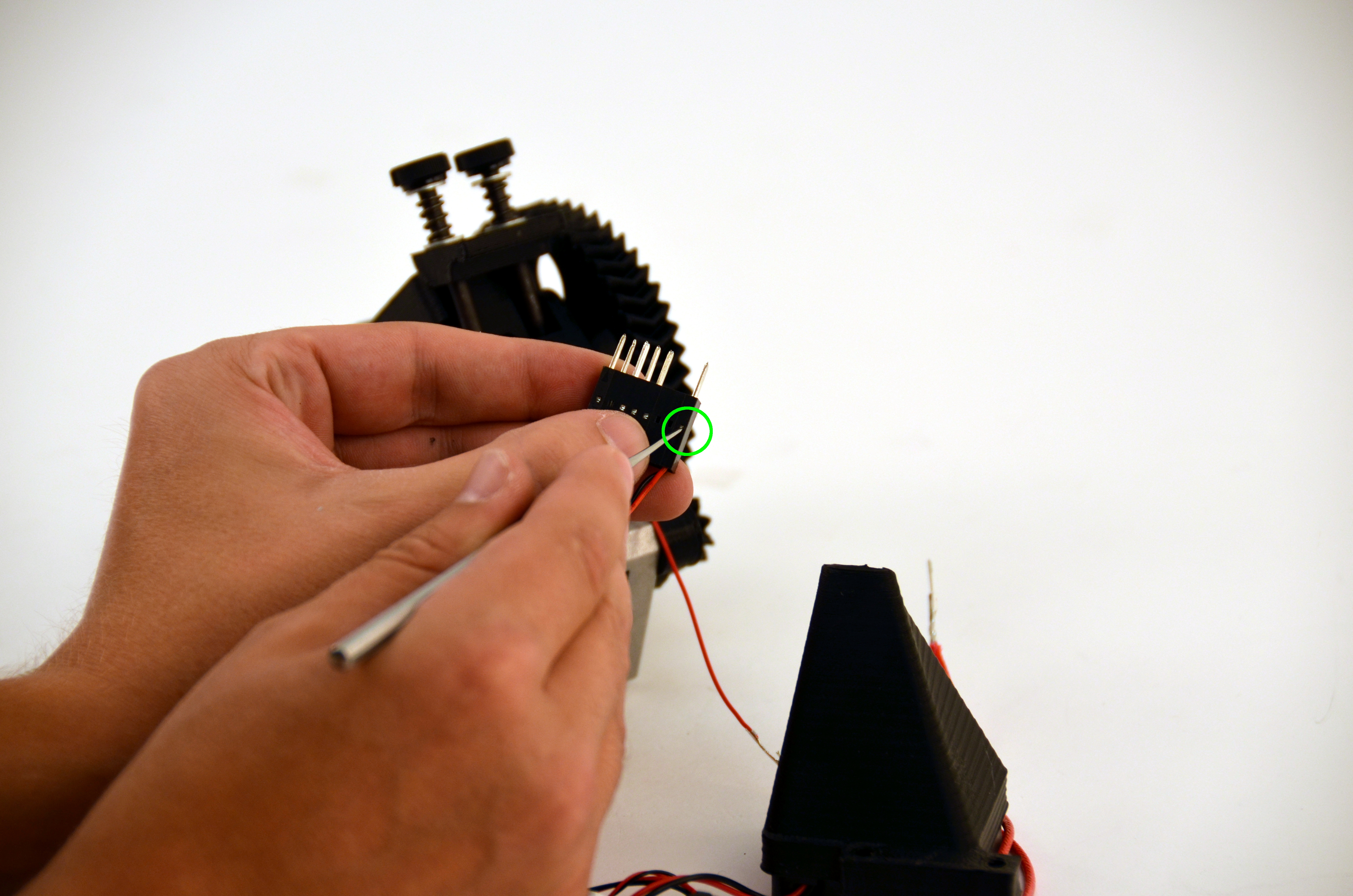
Using the dental pick included with your toolkit, gently push down on the catch that holds the pin in place. This will allow you to remove the existing pins.
Release and remove just the two larger red wires.
The pick is sharp. Be careful.
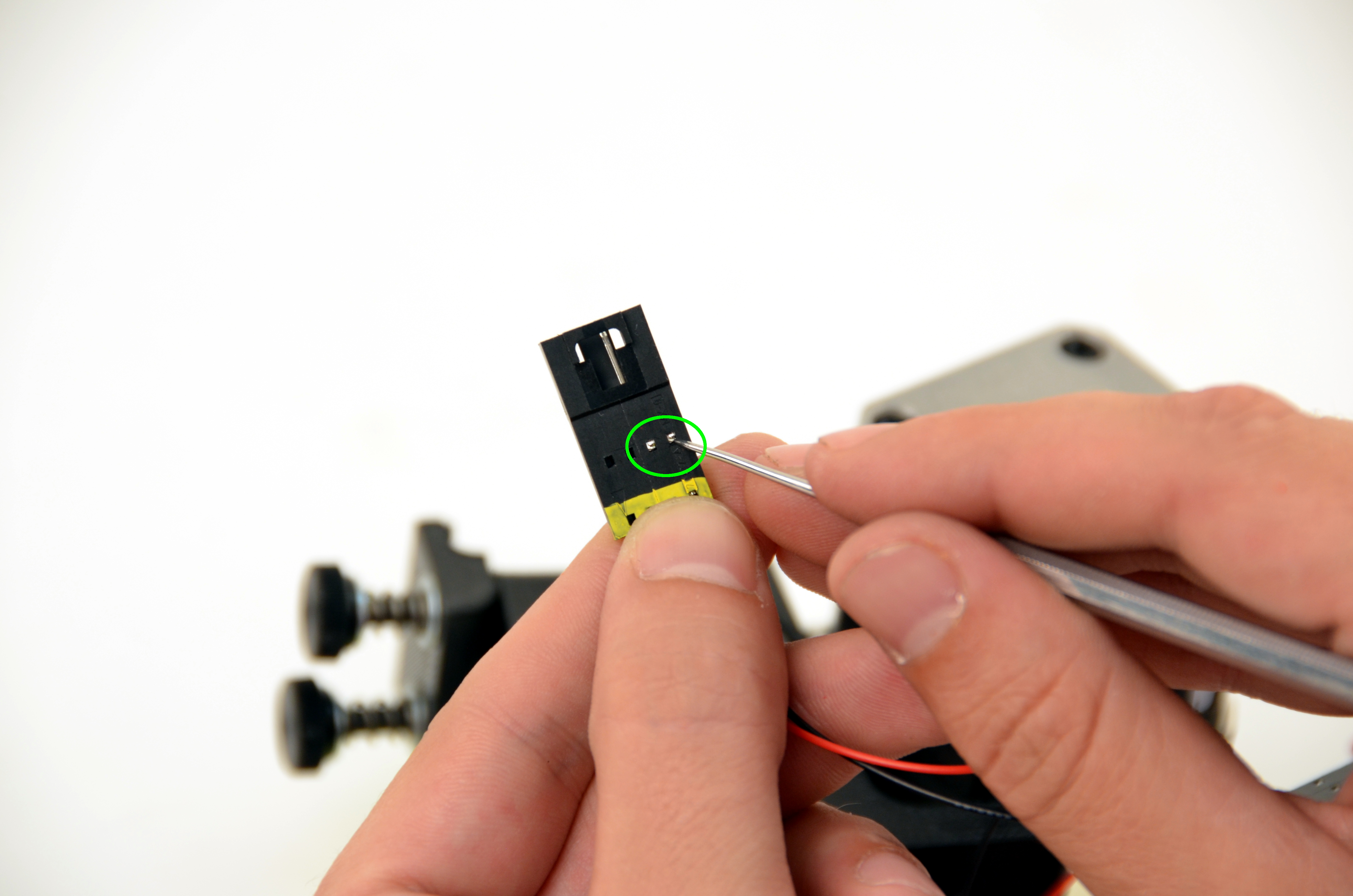
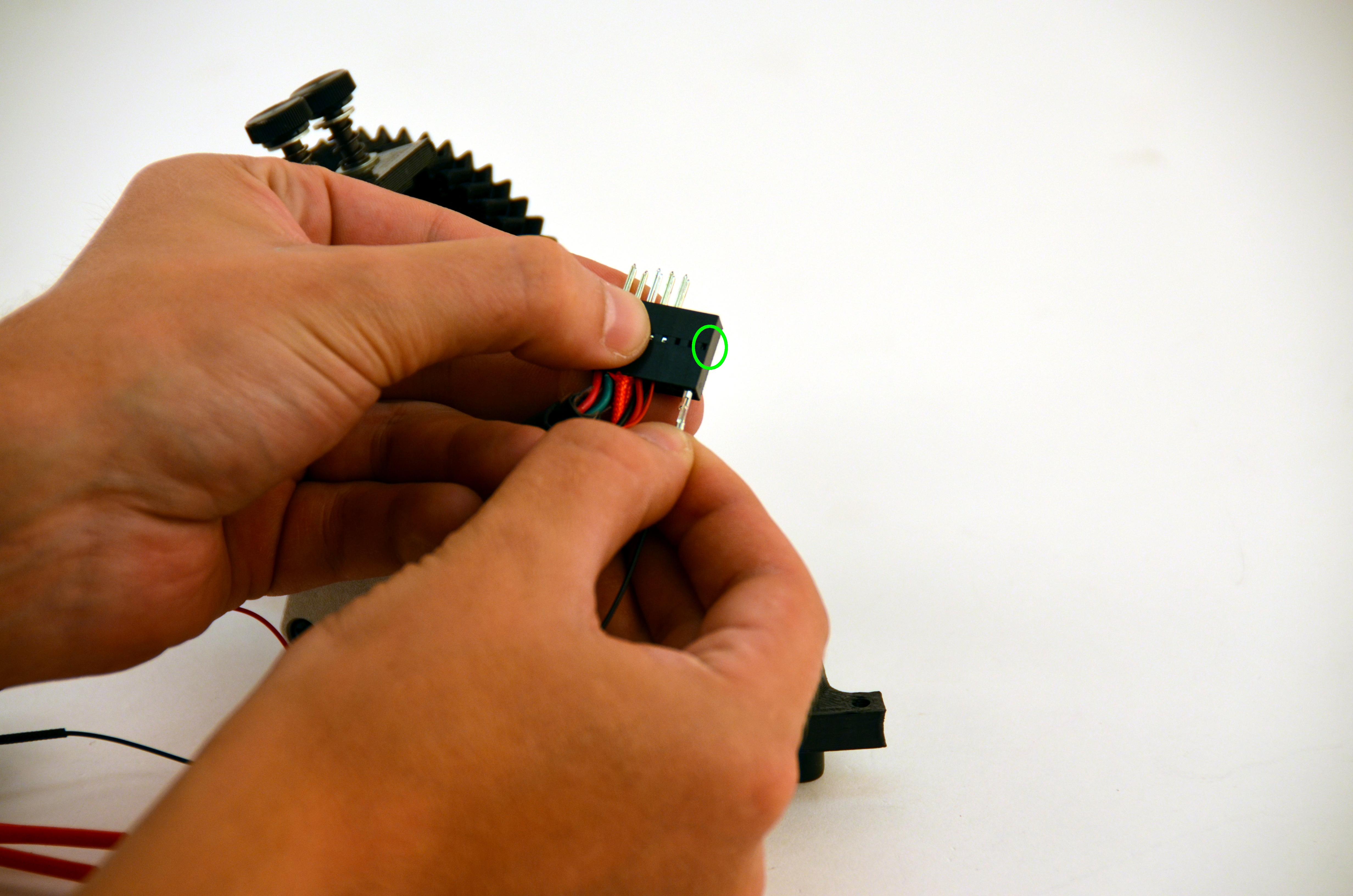
Using your dental pick, Gently raise the catch that was depressed in the previous step.
The pick is sharp. Be careful.


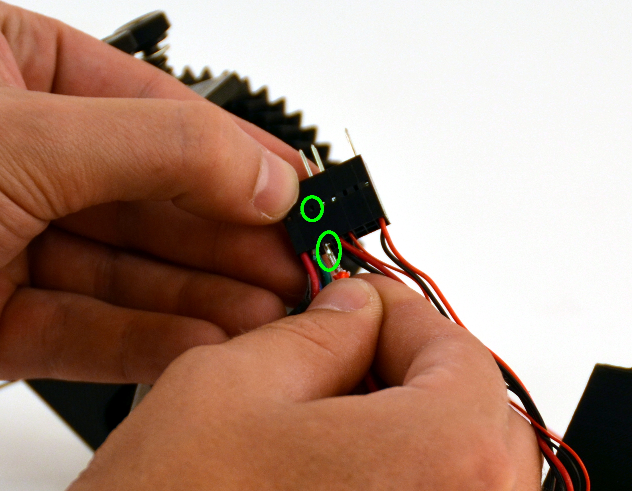
Push down on the catch that holds the pin in place using the dental pick. This will allow you to remove the existing pins.
Release and remove just the two larger red wires.
The pick is sharp. Be careful.

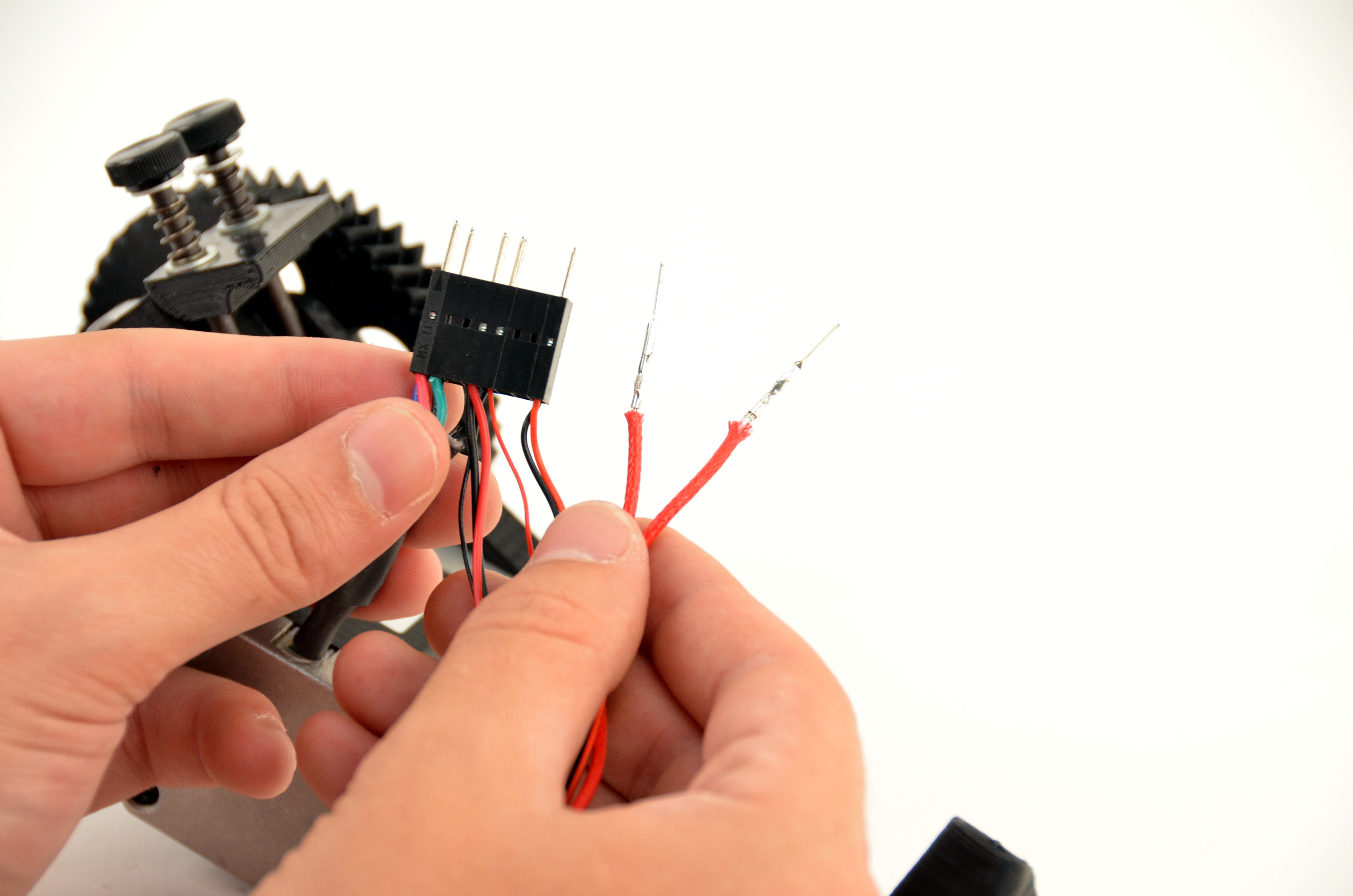
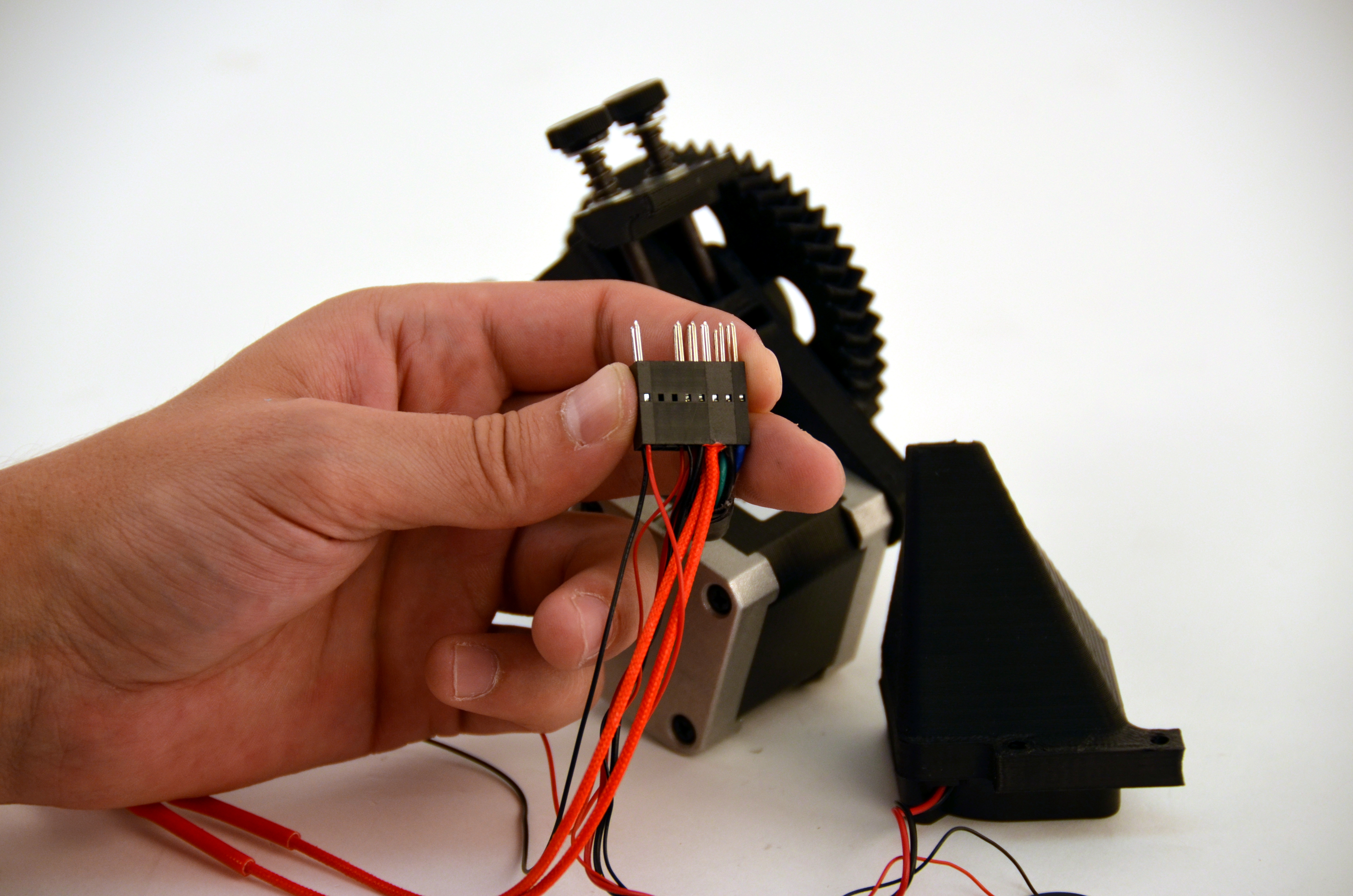
Insert the two red heater cartridge pins into the tool head connector.
Be sure the raised catch latches in the connector.
Reminder: Polarity does not matter.
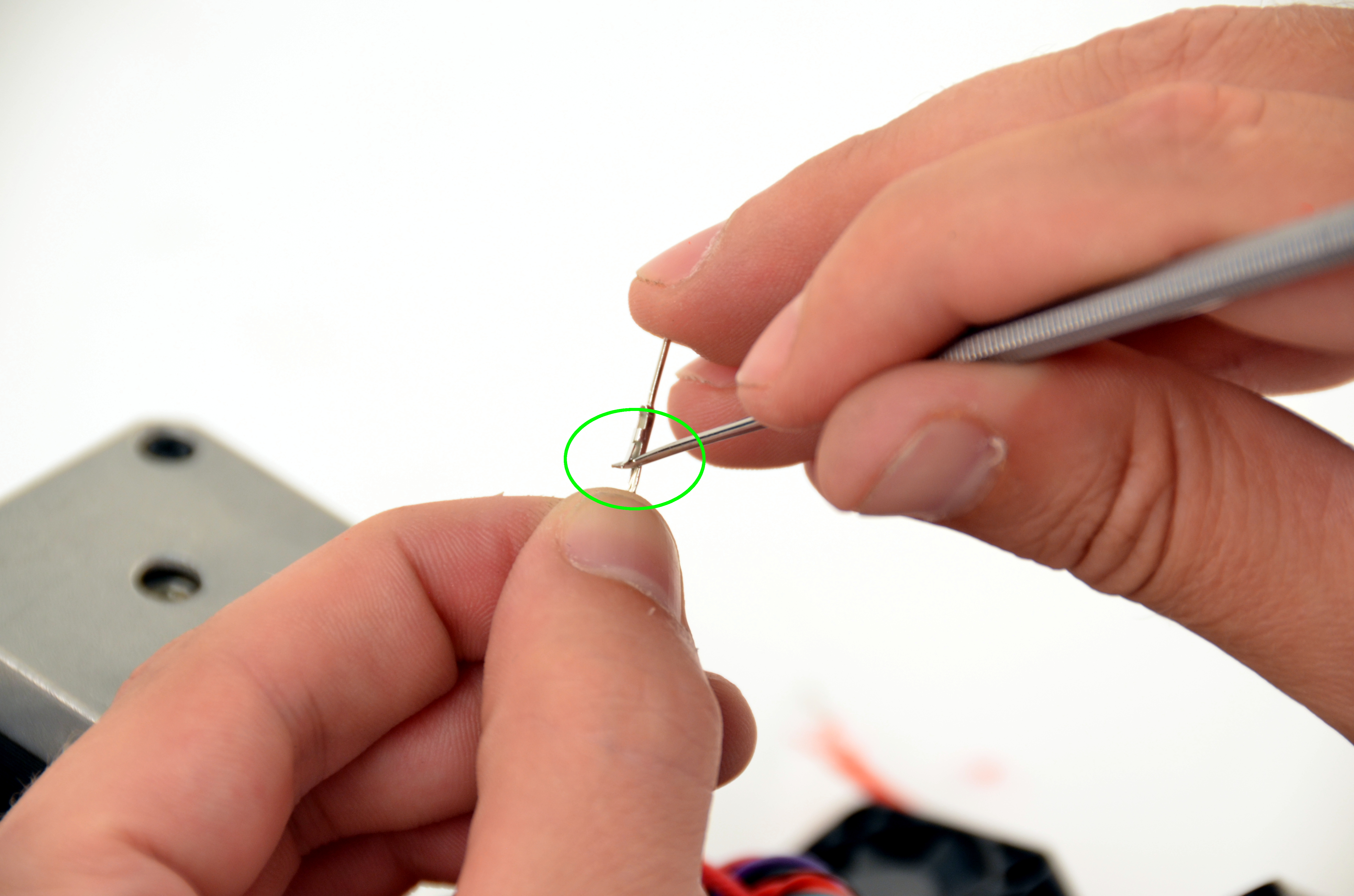
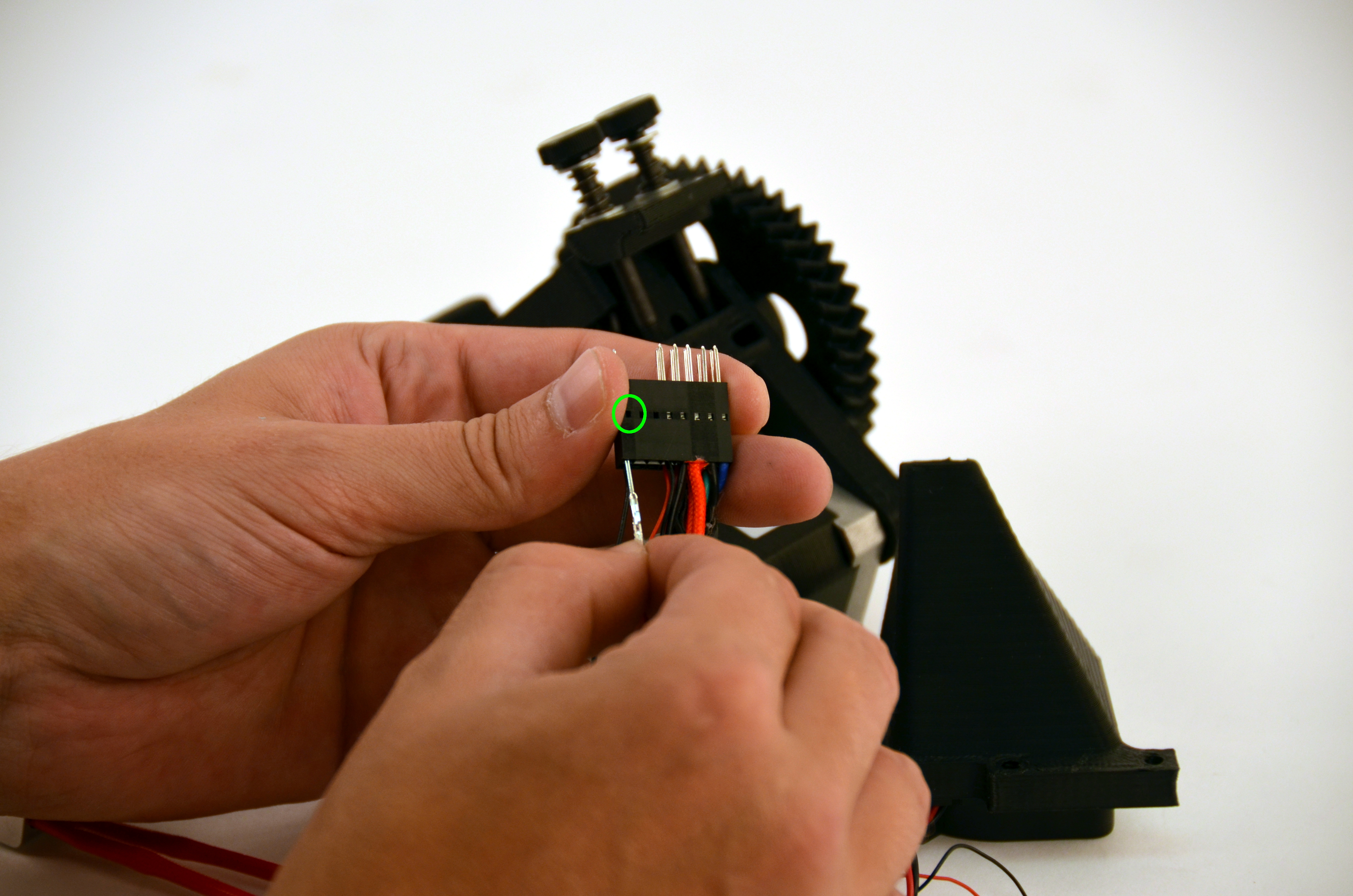
Release the new thermistor pins using the dental pick.
Set aside the original connector.
The pick is sharp. Be careful.

Using your dental pick, Gently raise the catch that was depressed in the previous step.
The pick is sharp. Be careful.
Release the original thermistor pins using the dental pick included with your tool kit.
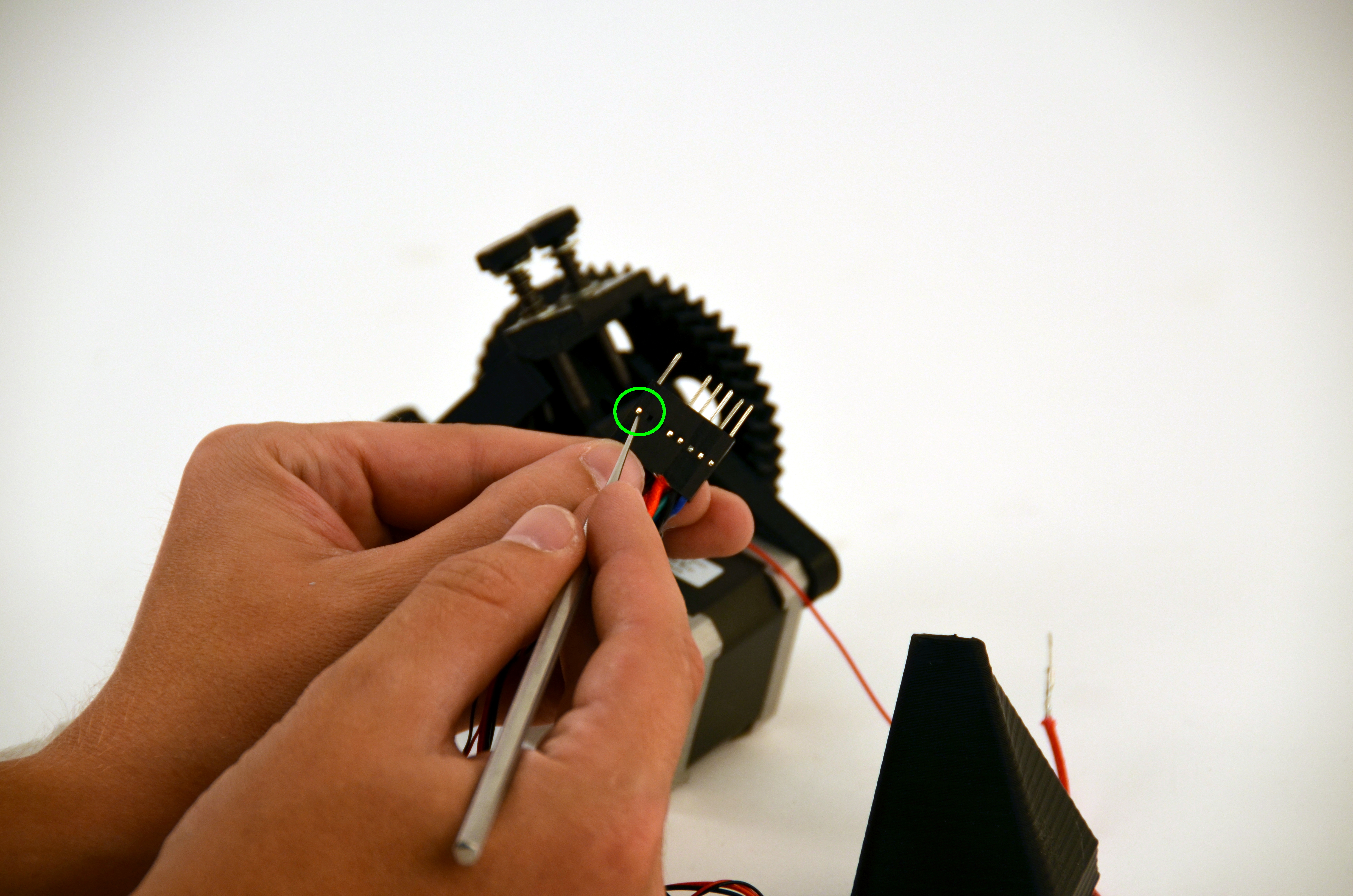
Insert the two thermistor wire pins into the connector.
Be sure the raised catch latches in the connector.
Reminder: Polarity does not matter.
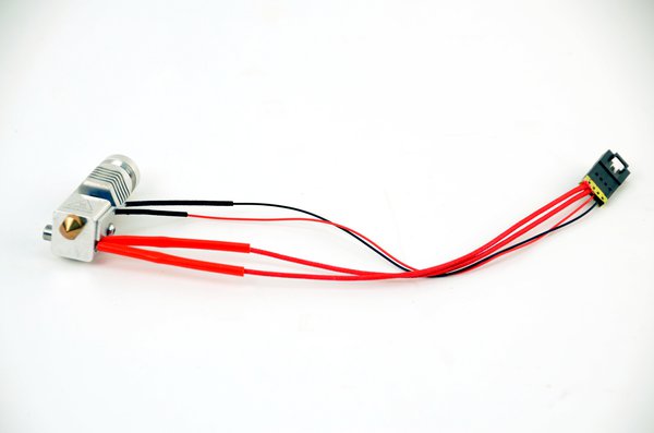
Rotate the hot end so the Hexagon text faces forward, and the thick red wires are coming out of the right hand side of the block.
To aid in aligning the extruder body and the hot end, feed a small length of filament through the extruder so the hot end settles into alignment with the extruder.
Install the 2 M3x15mm screws from the underside of the tool head, through the hot end mounting plate and into the extruder body by using the 4mm driver. Torque to 6 in*lbs.
Caution: the extruder body can crack if there is too much torque applied to the mounting screws. Do not apply more than 6 in*lbs to the 2 M3x15mm screws.
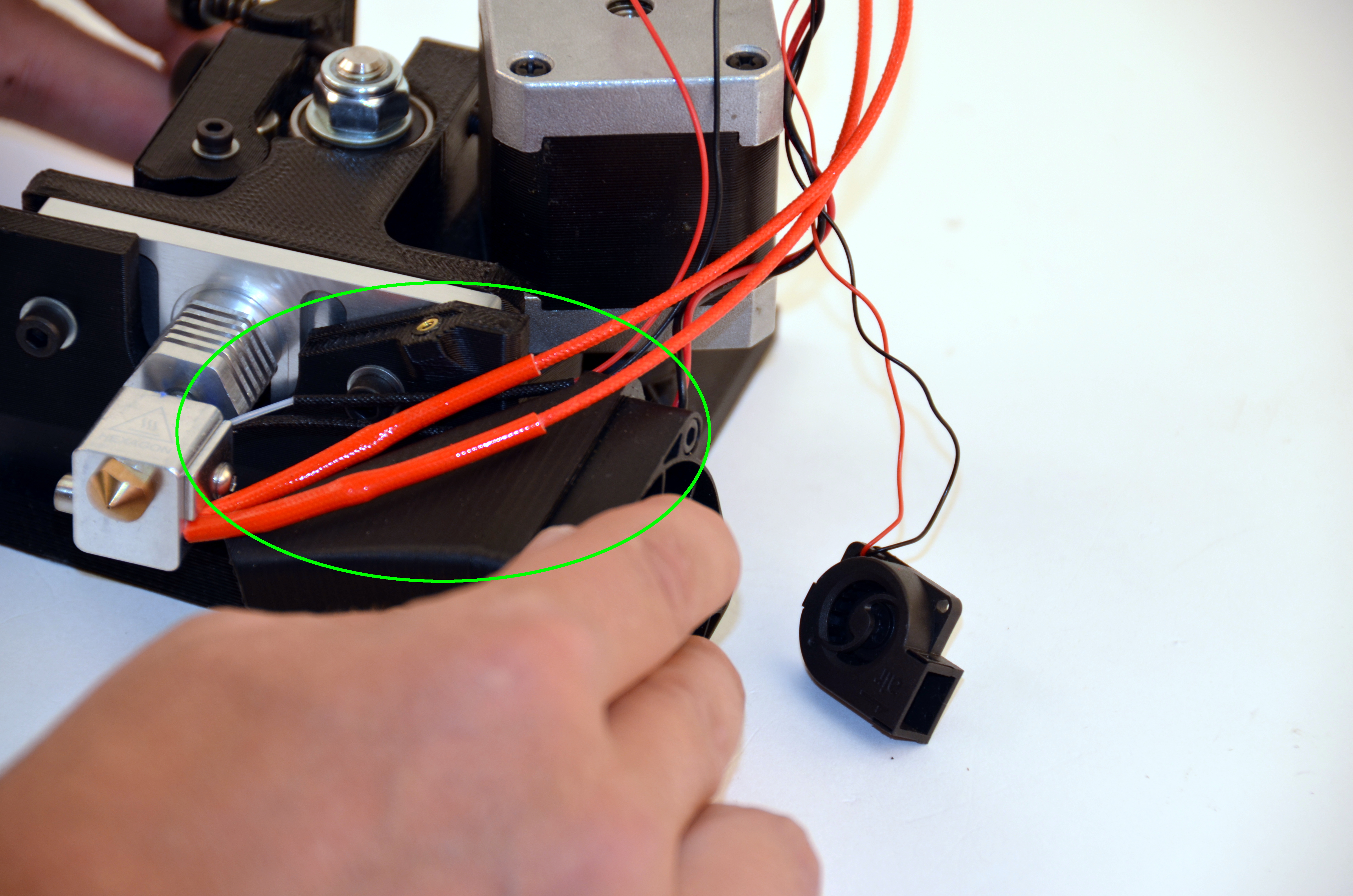
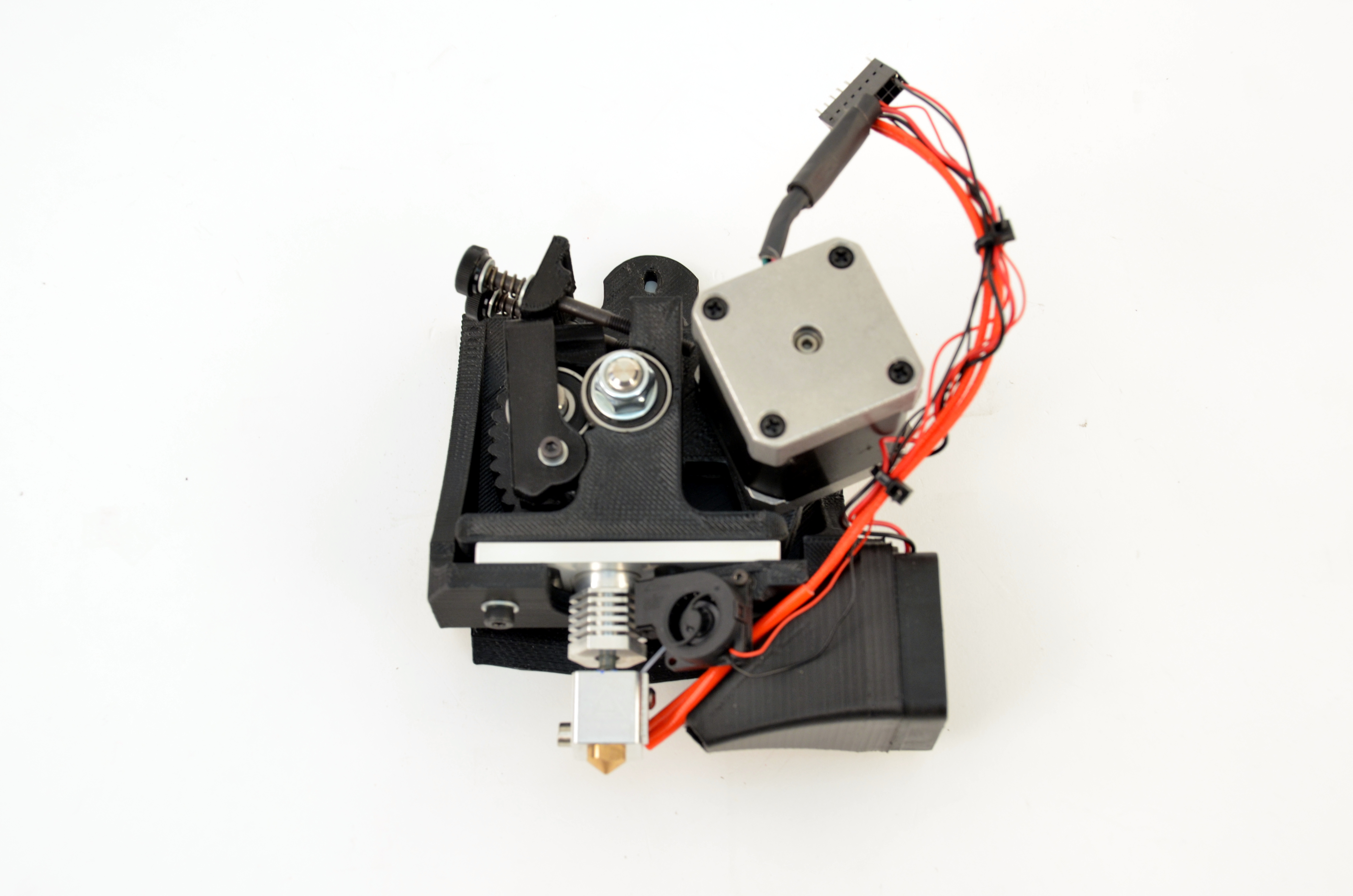
Route the wires towards the front right-hand side of the tool head.
Using your 2.5mm driver, install the extruder fan mount onto the right-hand side of the toolhead


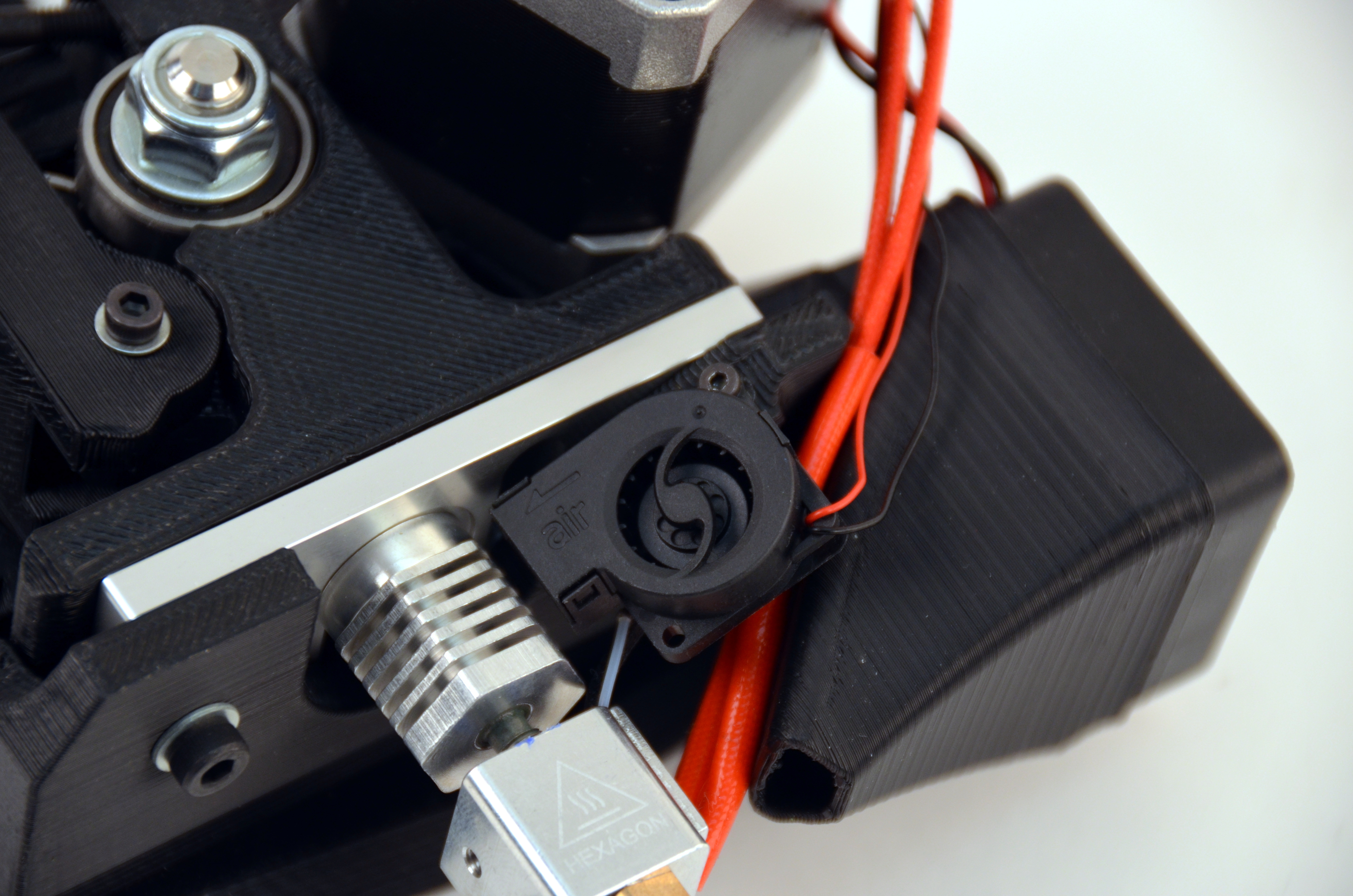
Using your 1.5mm driver, install the Micro Blower back onto the tool head.

Use zip tie(s) to ensure your wiring harness does not get caught in the gears.
This will prevent damage to your Tool Head and Hot End.
Using your 2.5mm driver secure the toolhead back into the X axis carriage.

Connect the tool head to the existing wiring harness.
Match the pin orientation.

Verify everything is working properly:
Print your favorite test object to verify functionality.
Questions? Contact Technical Support by emailing Support@LulzBot.com, or by calling 1-970-377-1111.