Open HardwareAssembly Instructions
Guides for installation and assembly of the LulzBot line of products made by FAME 3D LLC.
Guides for installation and assembly of the LulzBot line of products made by FAME 3D LLC.
WARNING:
At Aleph Objects, Inc. we respect your freedom to modify your LulzBot™ 3D printer. Any modifications or attempted repairs that cause damage are not covered under the Warranty.
Questions? Contact Technical Support by emailing Support@LulzBot.com, or by calling +1-970-377-1111.
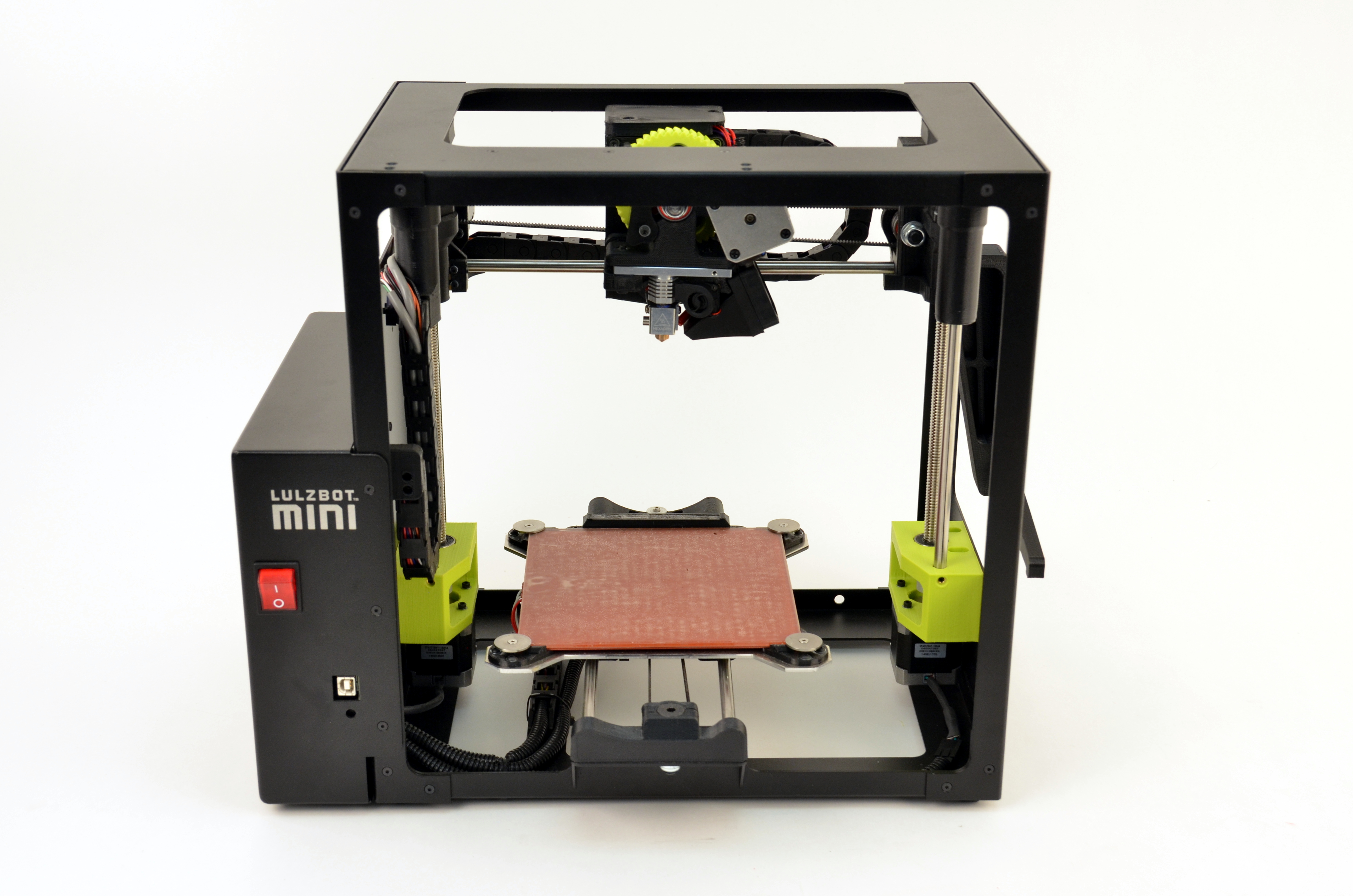
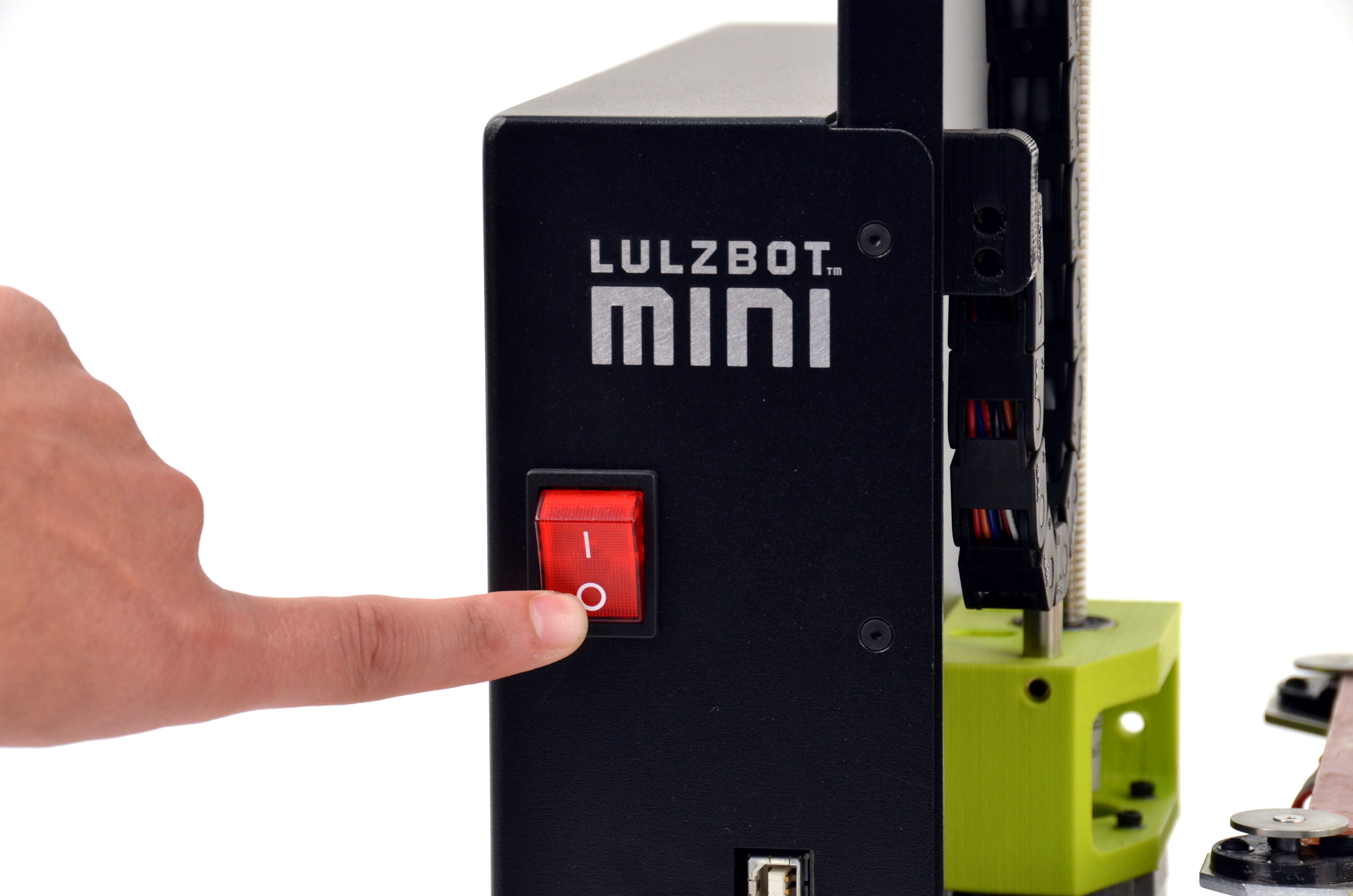
Power down and unplug your printer.
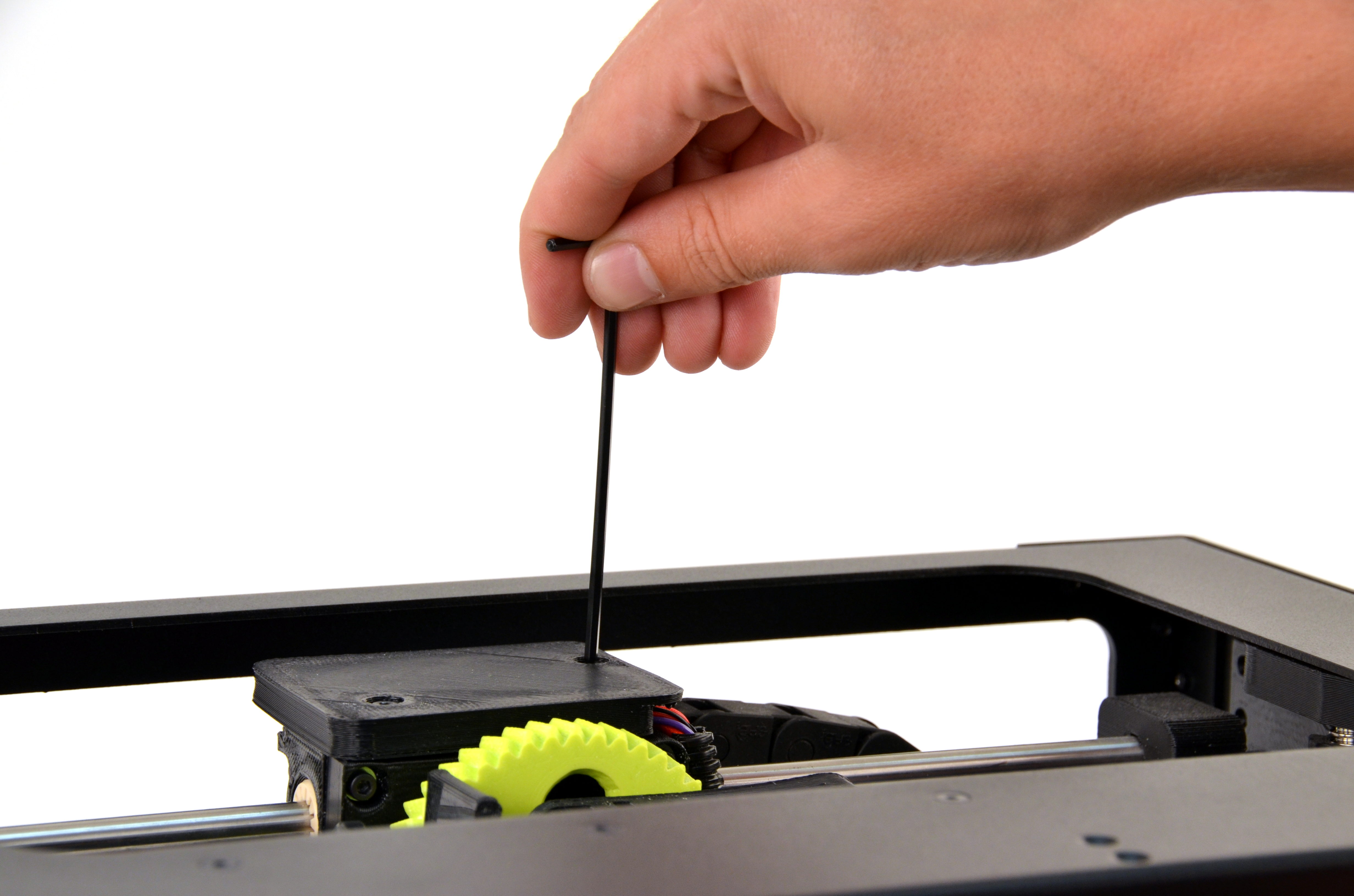
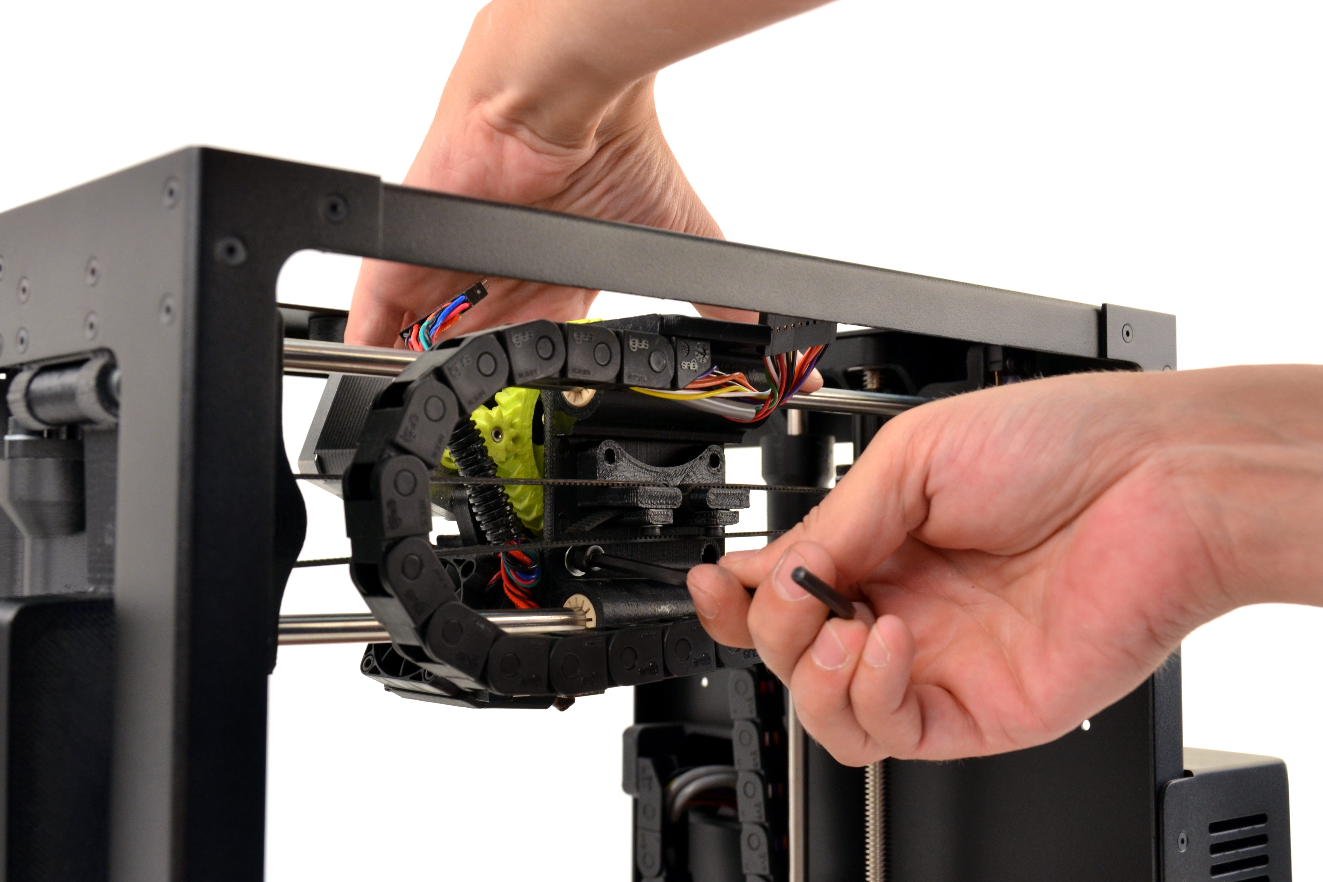
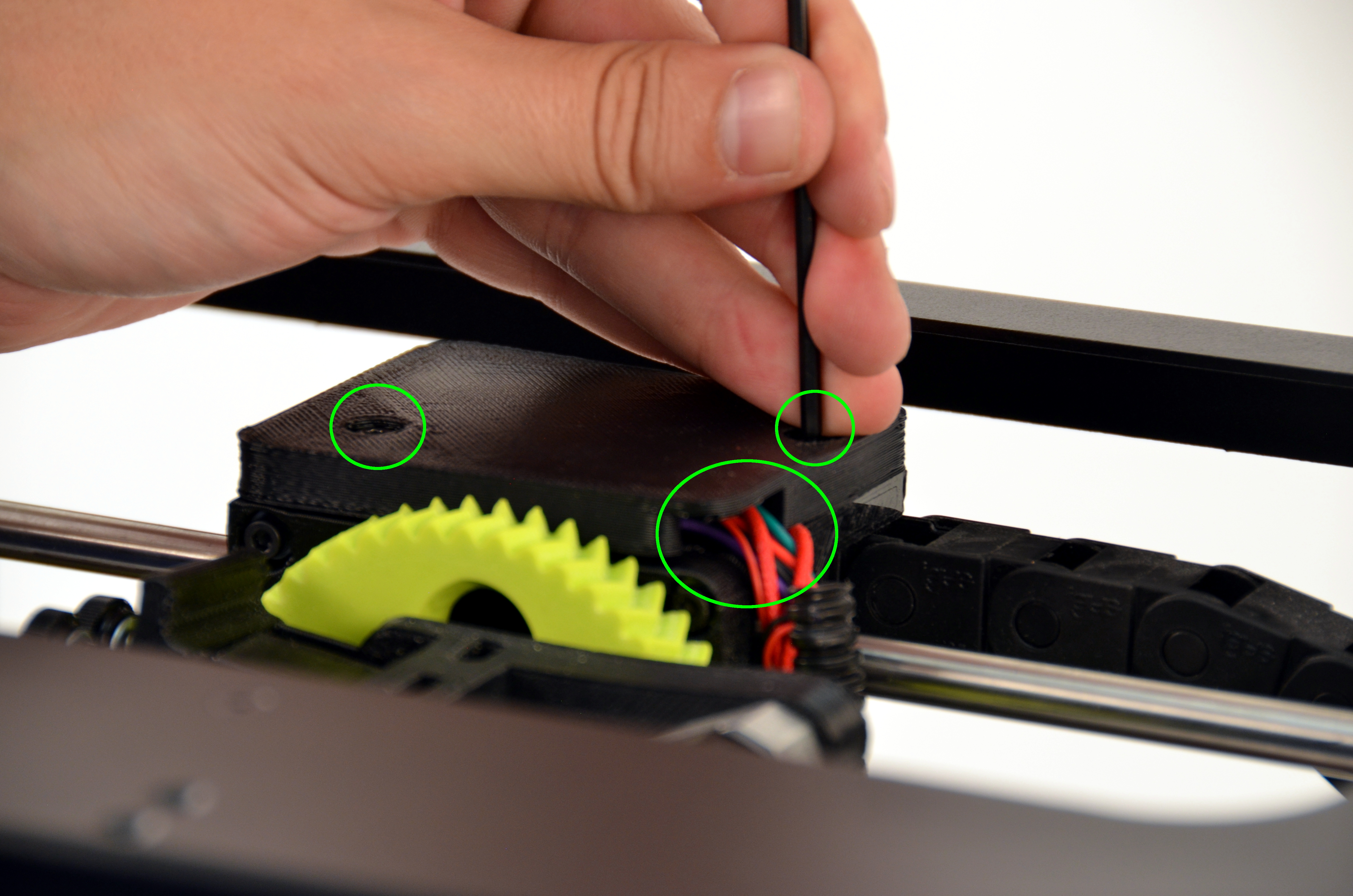
Using your 2.5mm driver, unscrew the two M3 screws that secure the connector cover on the X axis carriage.
Once removed, disconnect the 16 pin connector.

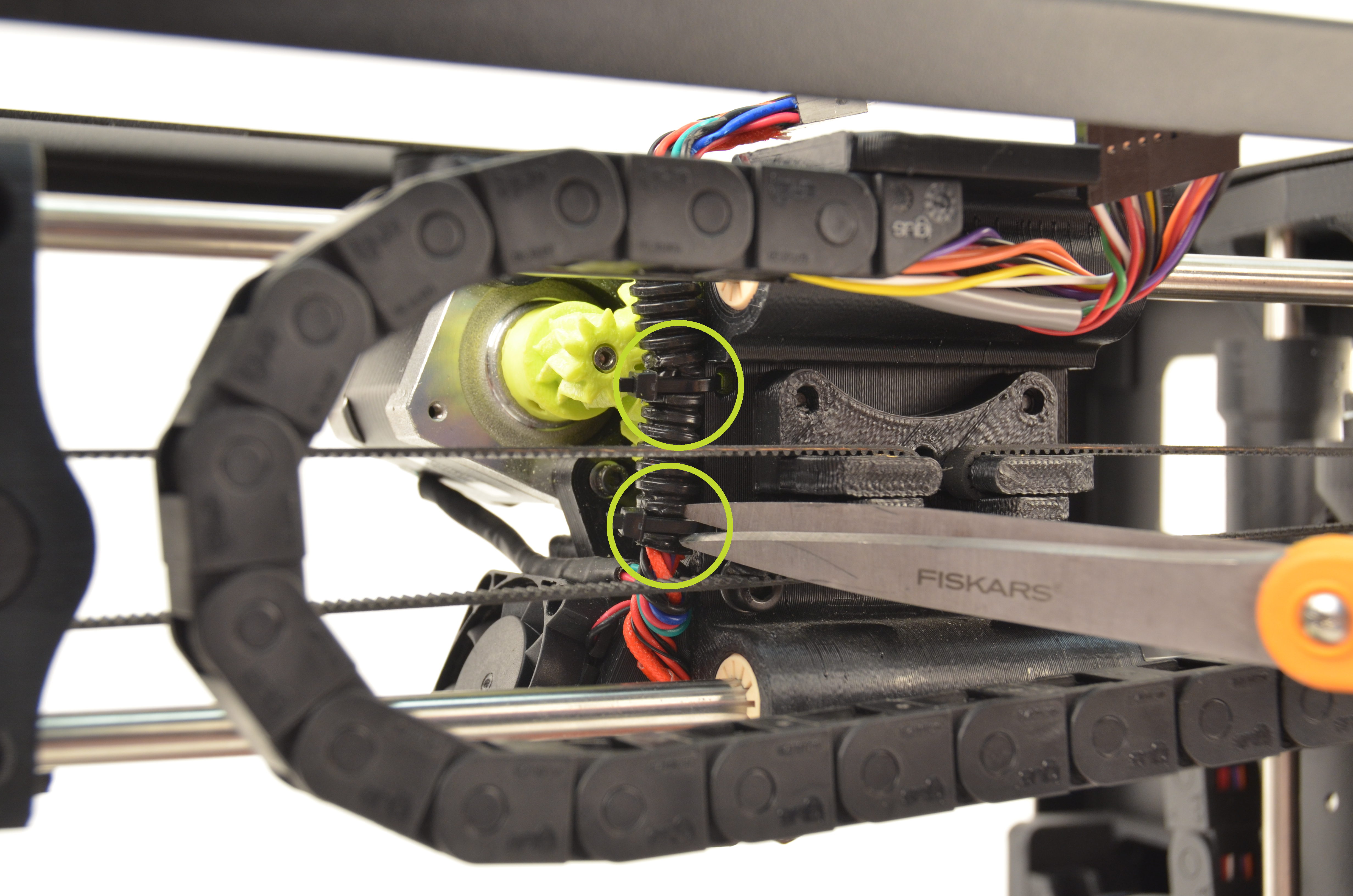
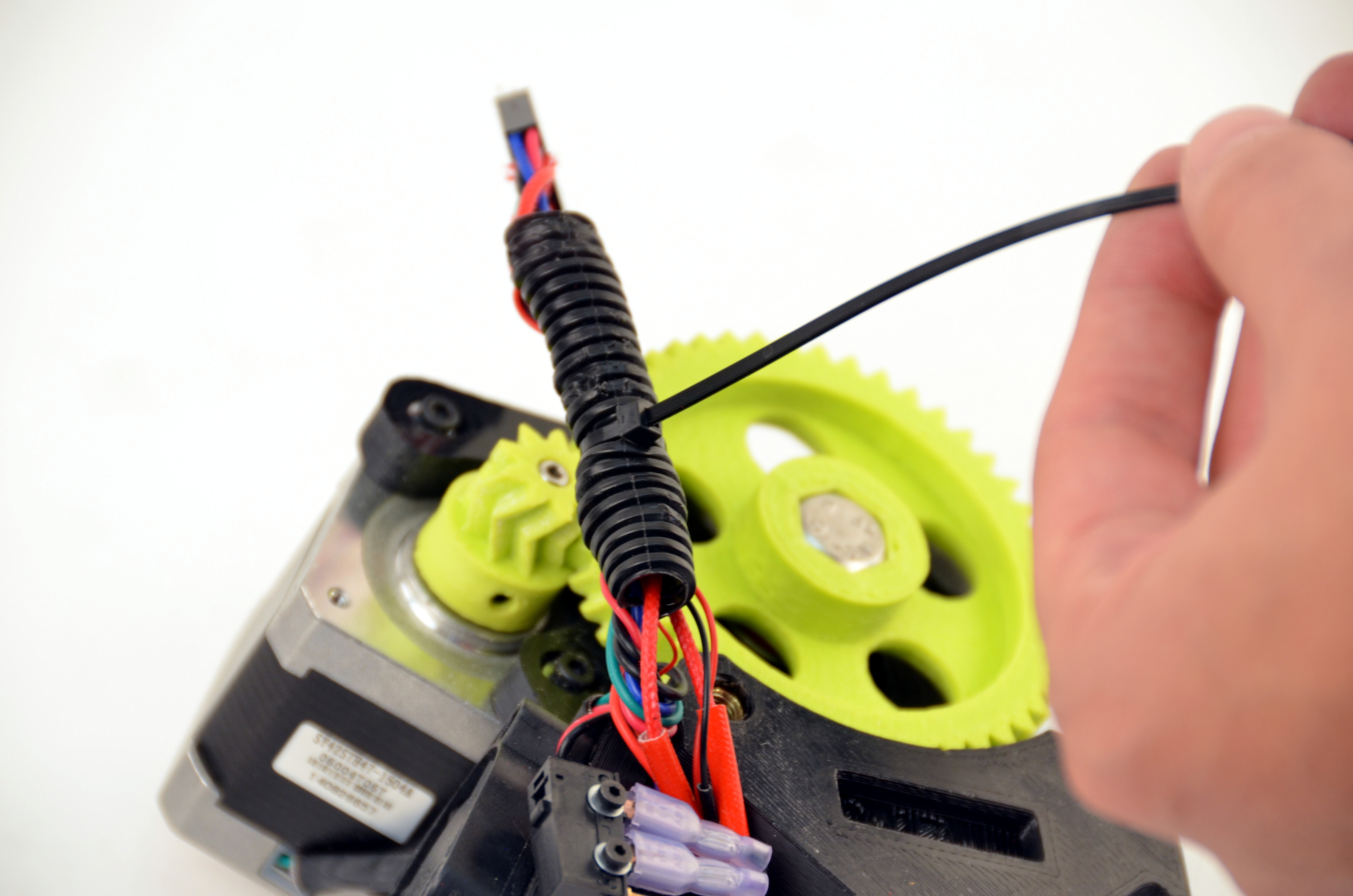
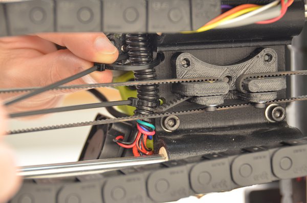
Cut the two zip ties holding the hot end harness to the X axis carriage.
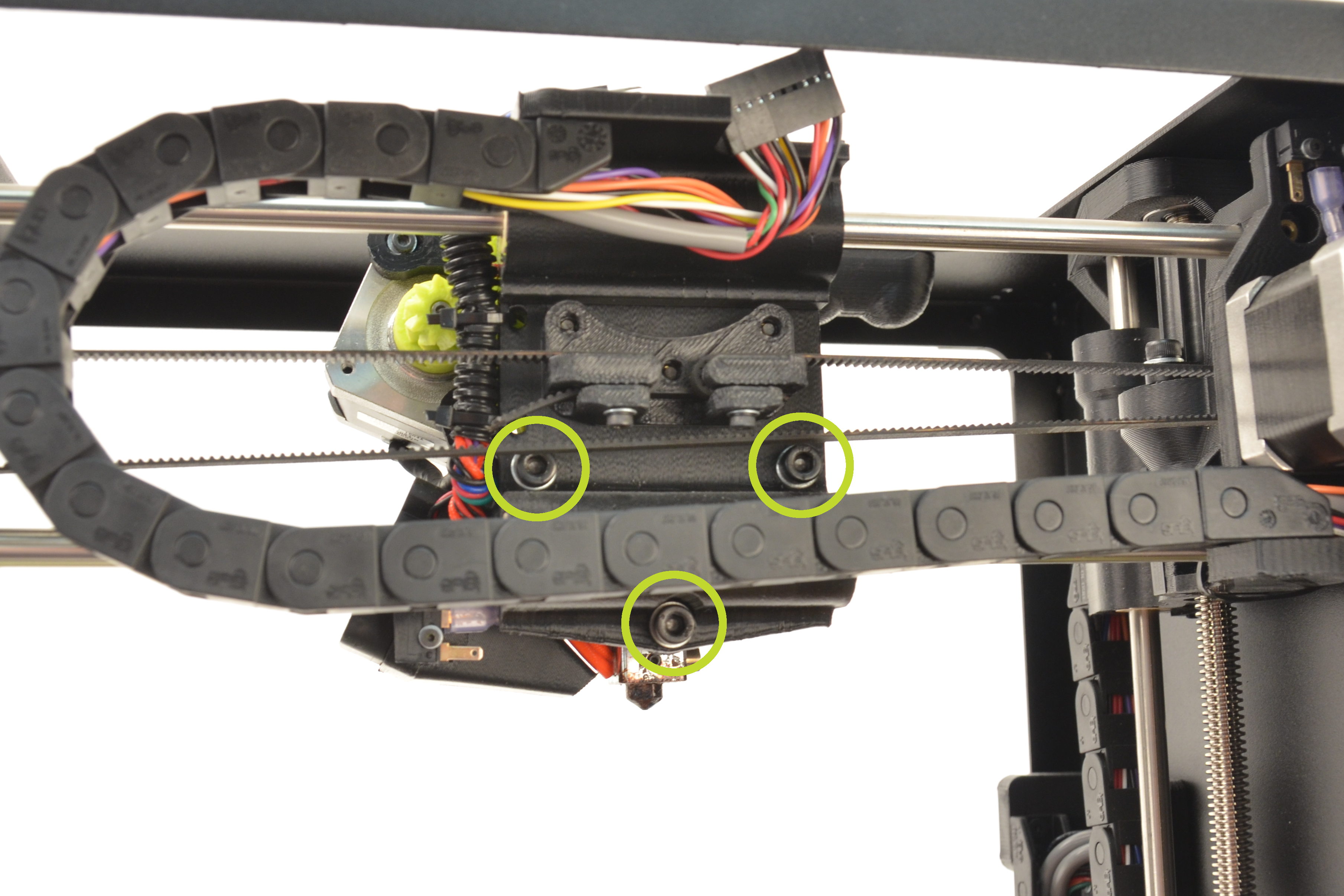
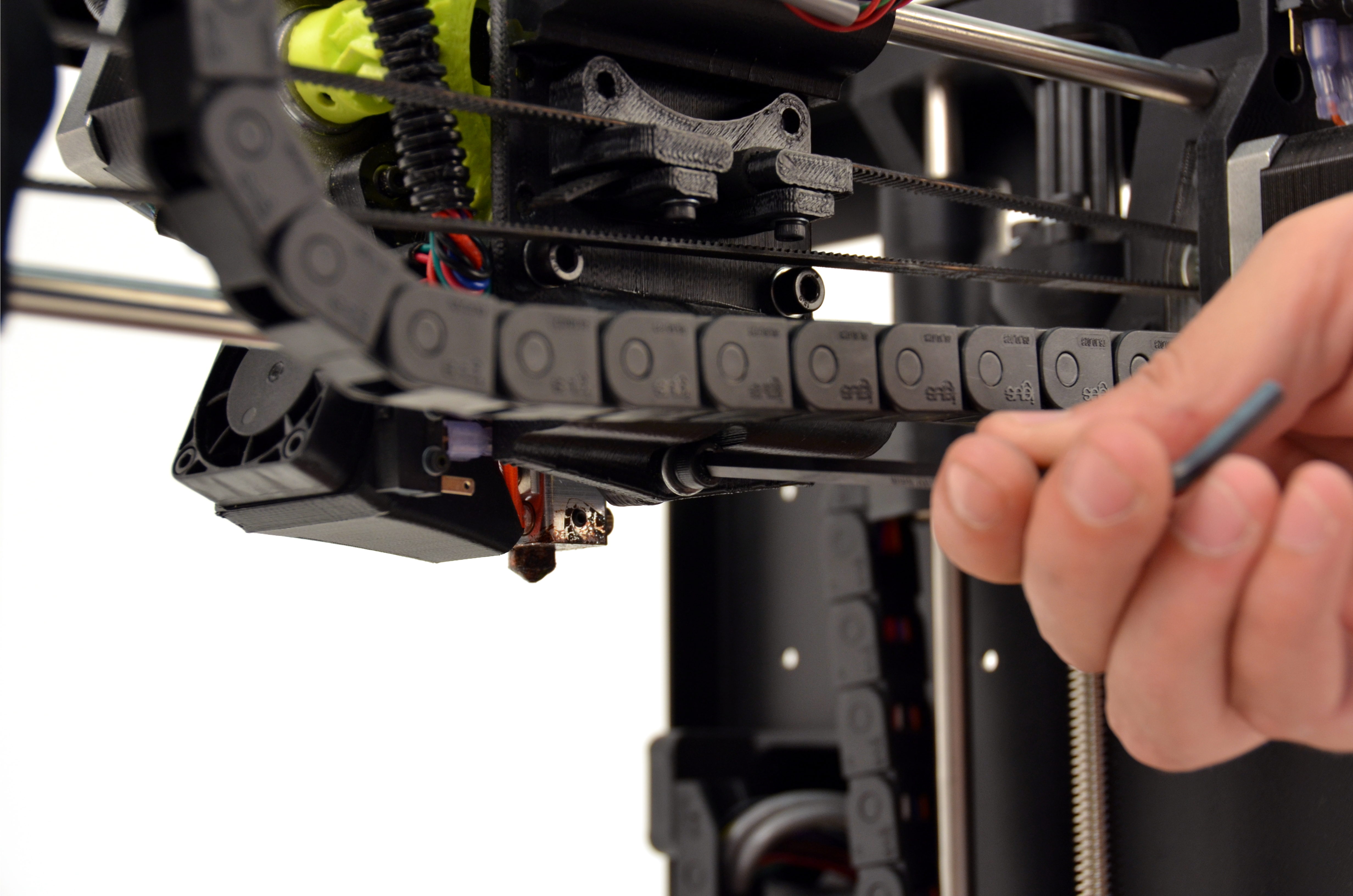
The tool head is attached with three screws. The print surface can be damaged if the tool head is allowed to fall onto the print surface.
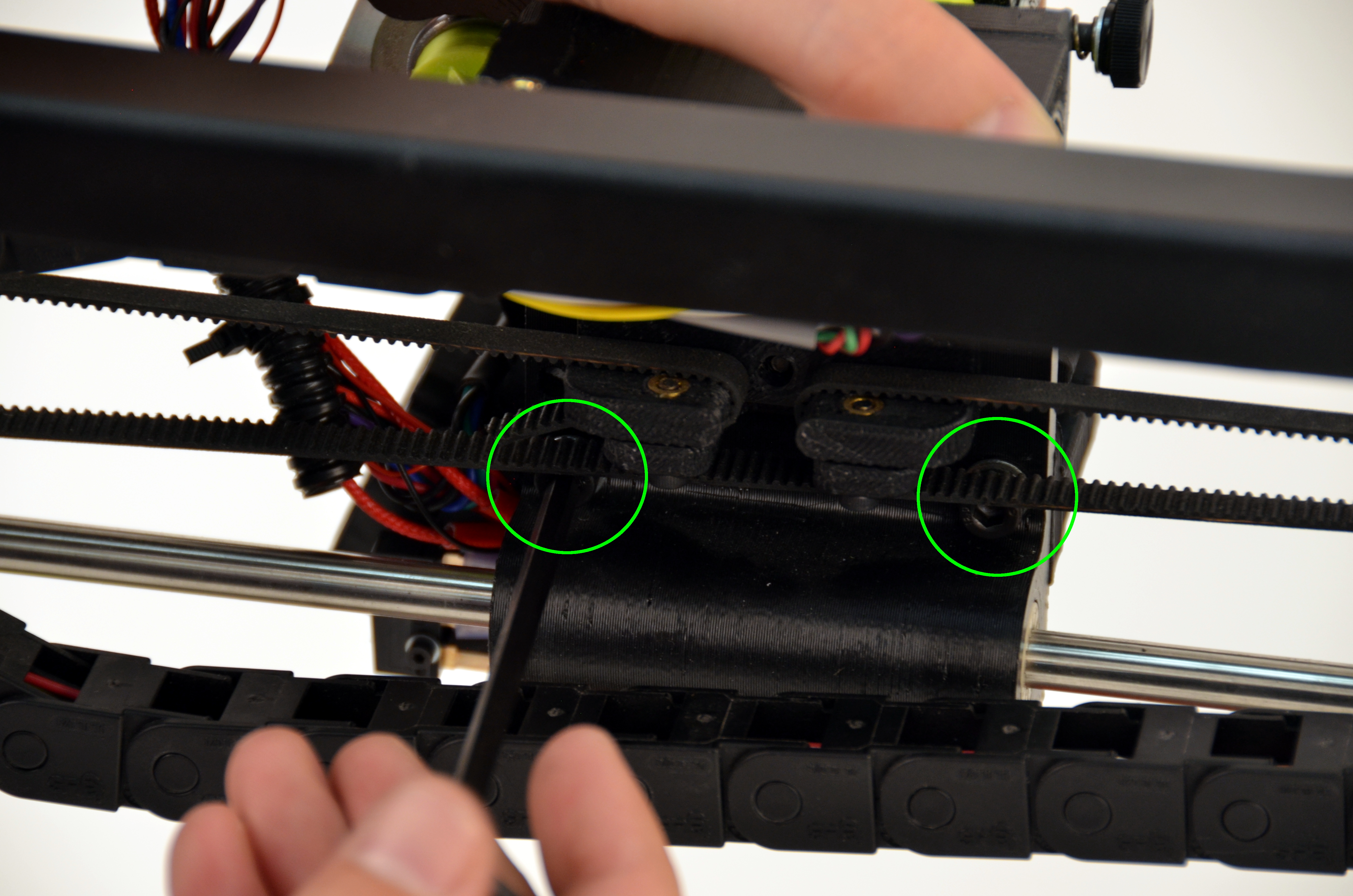
With one hand, support the tool head.
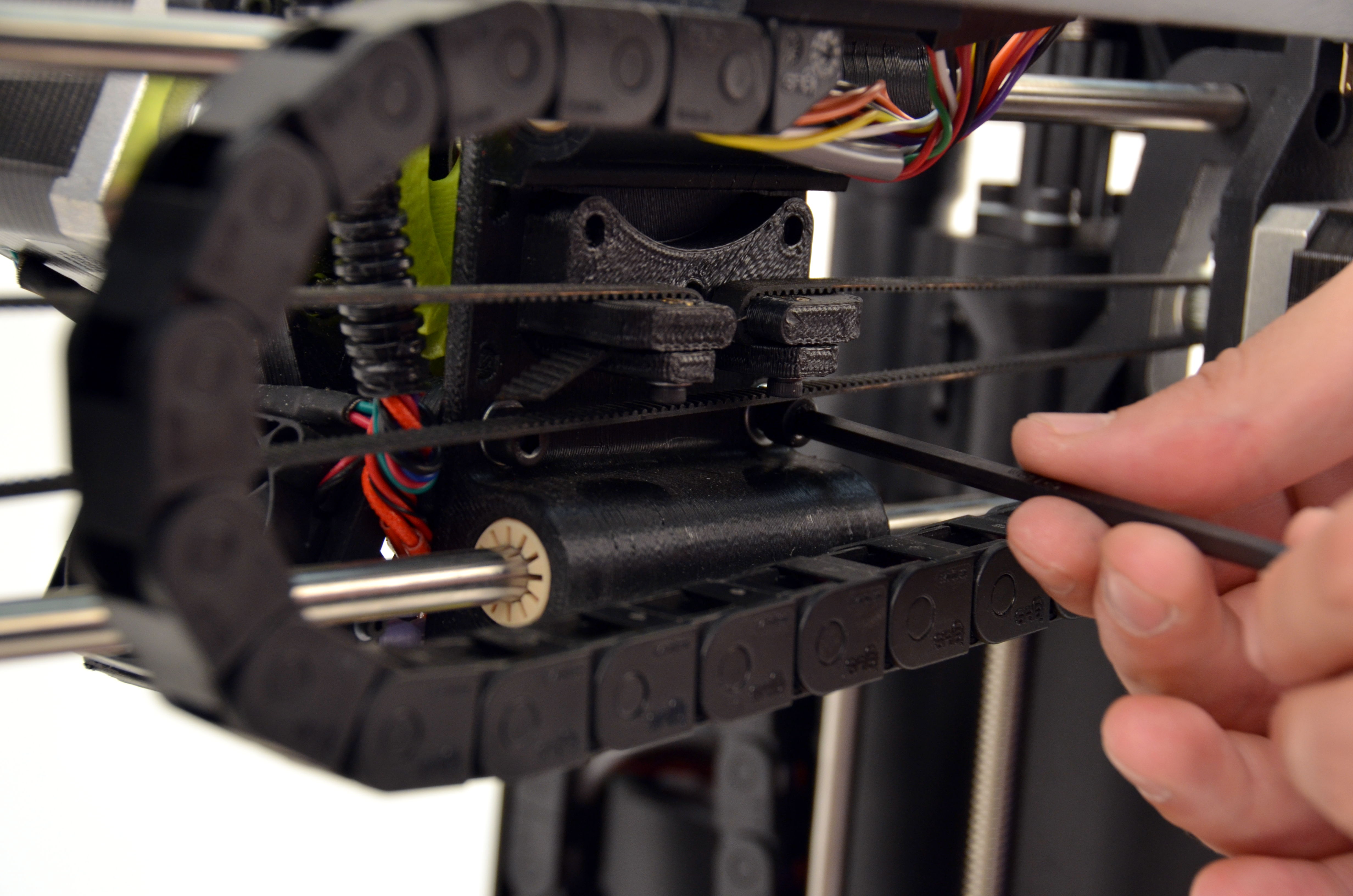
Using the 4mm driver, unscrew the three M5 screws securing the tool head to the X axis carriage.
Remove the bottom screw first, followed by the remaining two screws.
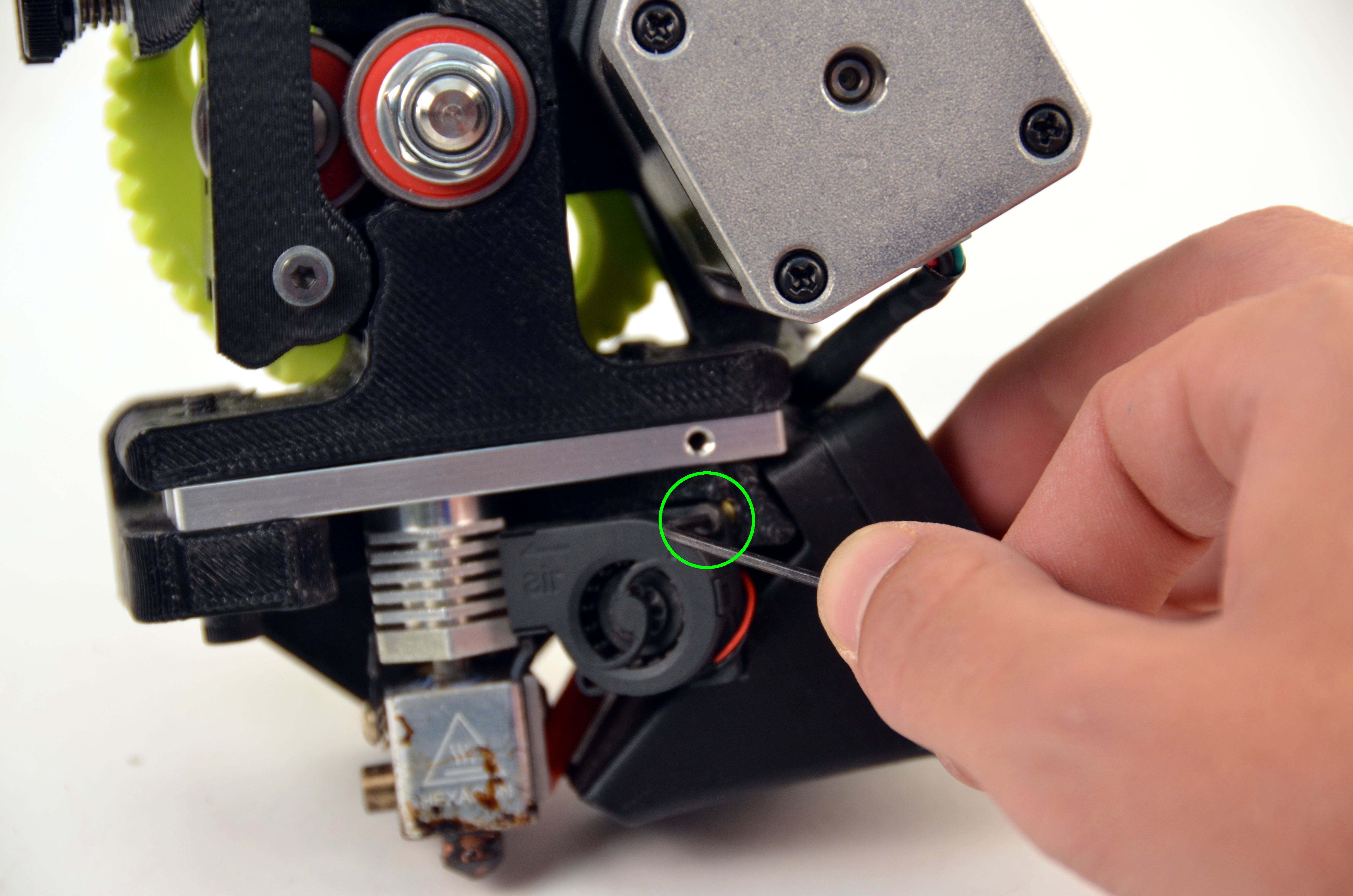
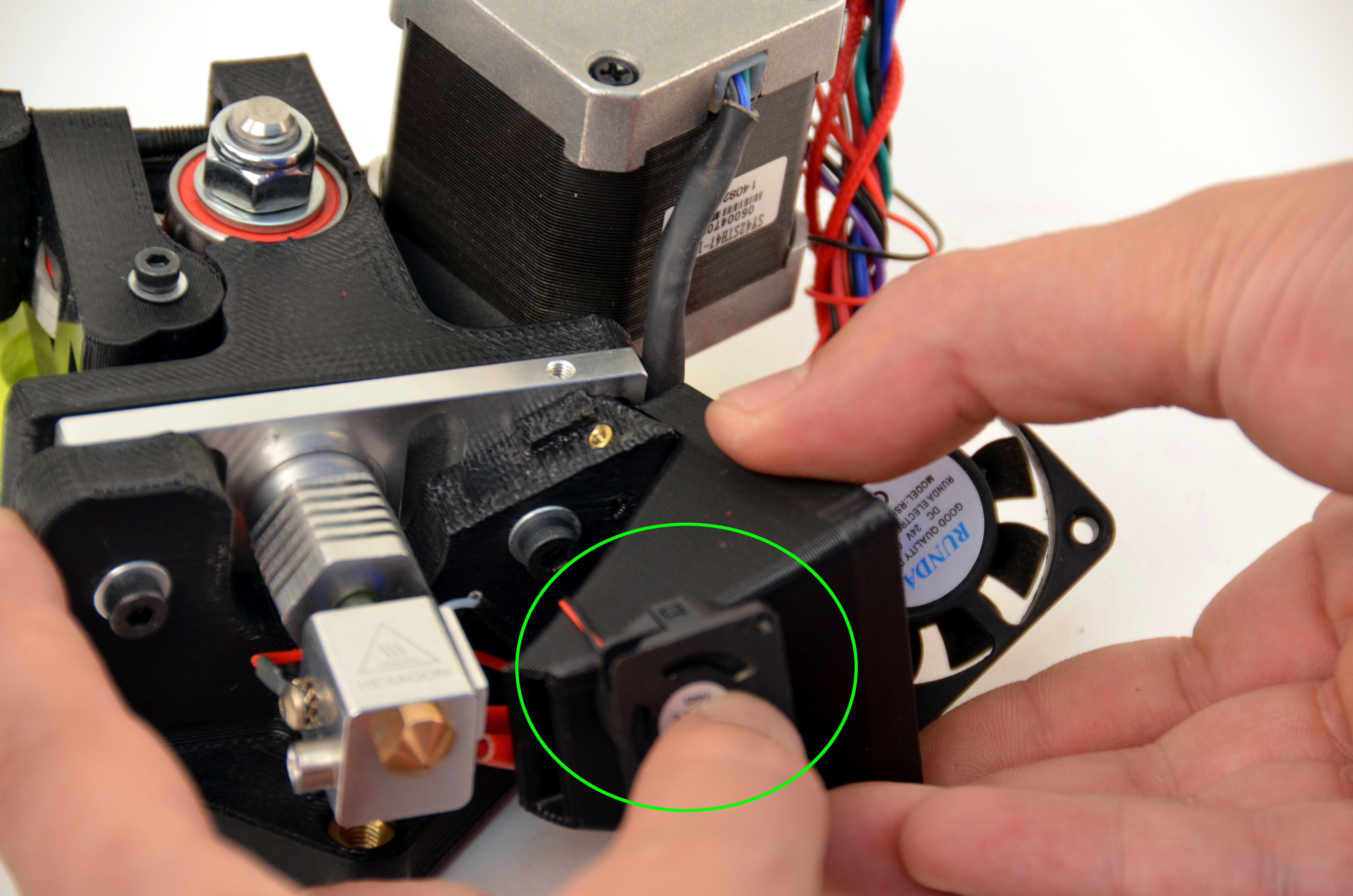
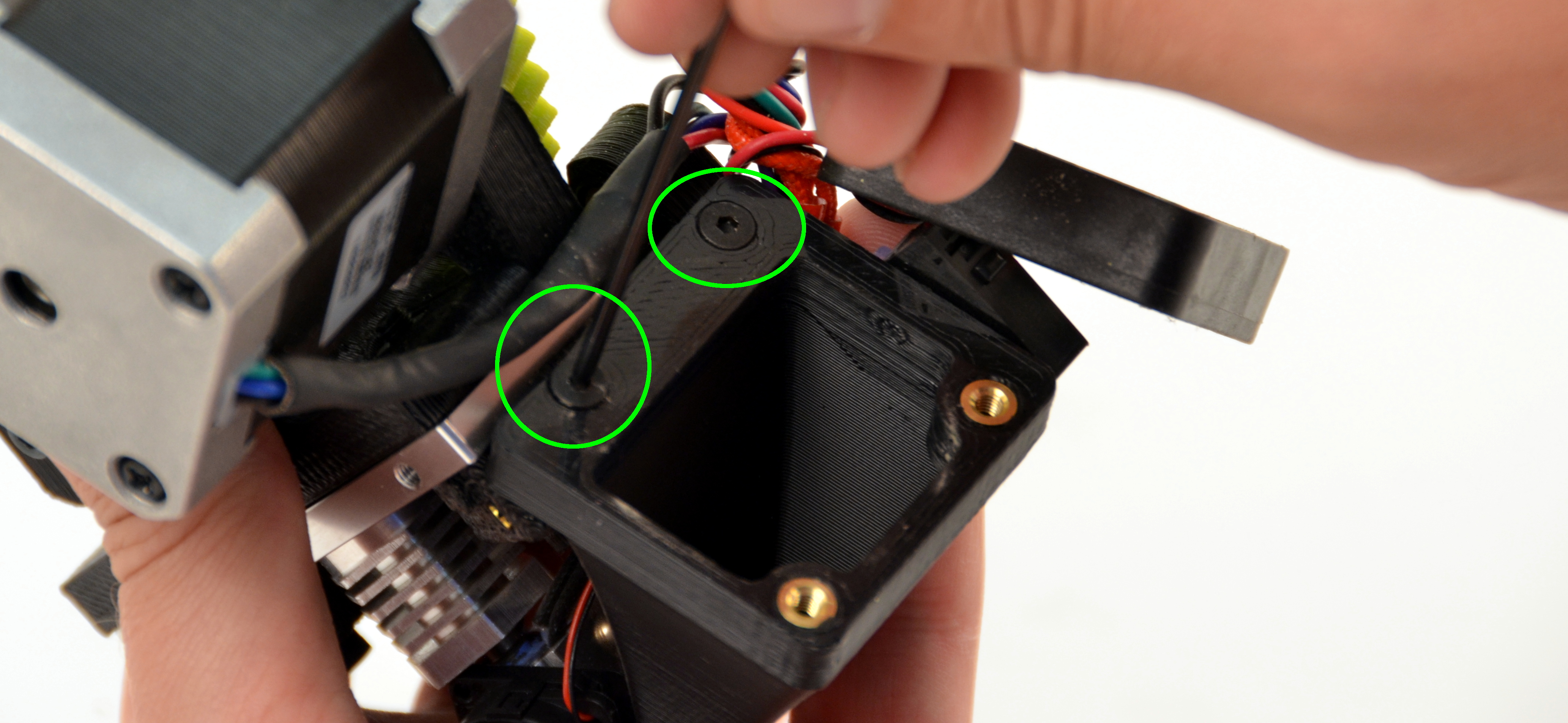
Using your 1.5mm driver, remove the screw holding the micro blower in place and set the screw aside.
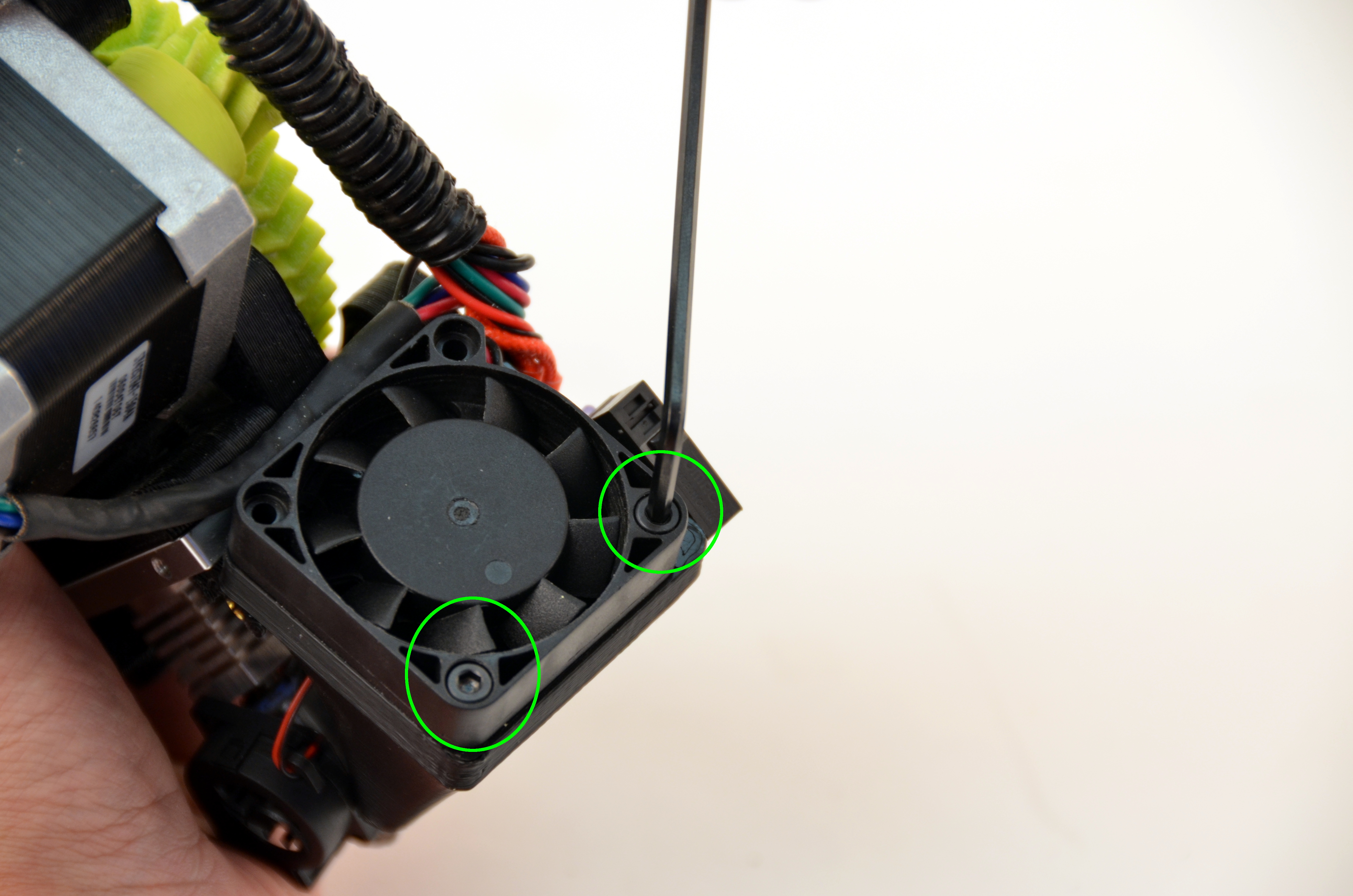
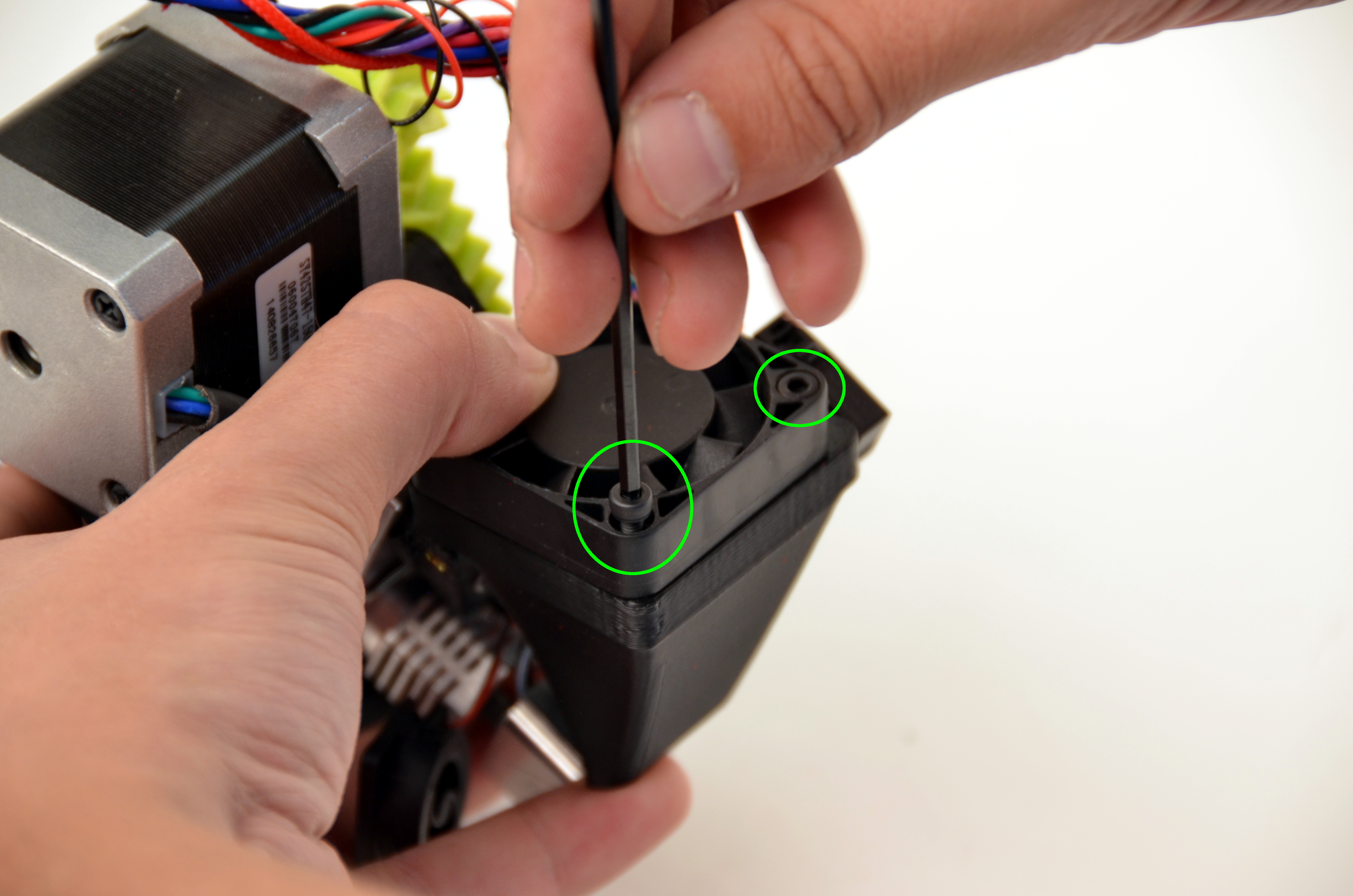
Using your 2.5mm driver, remove the two screws holding the extruder fan to the fan mount.
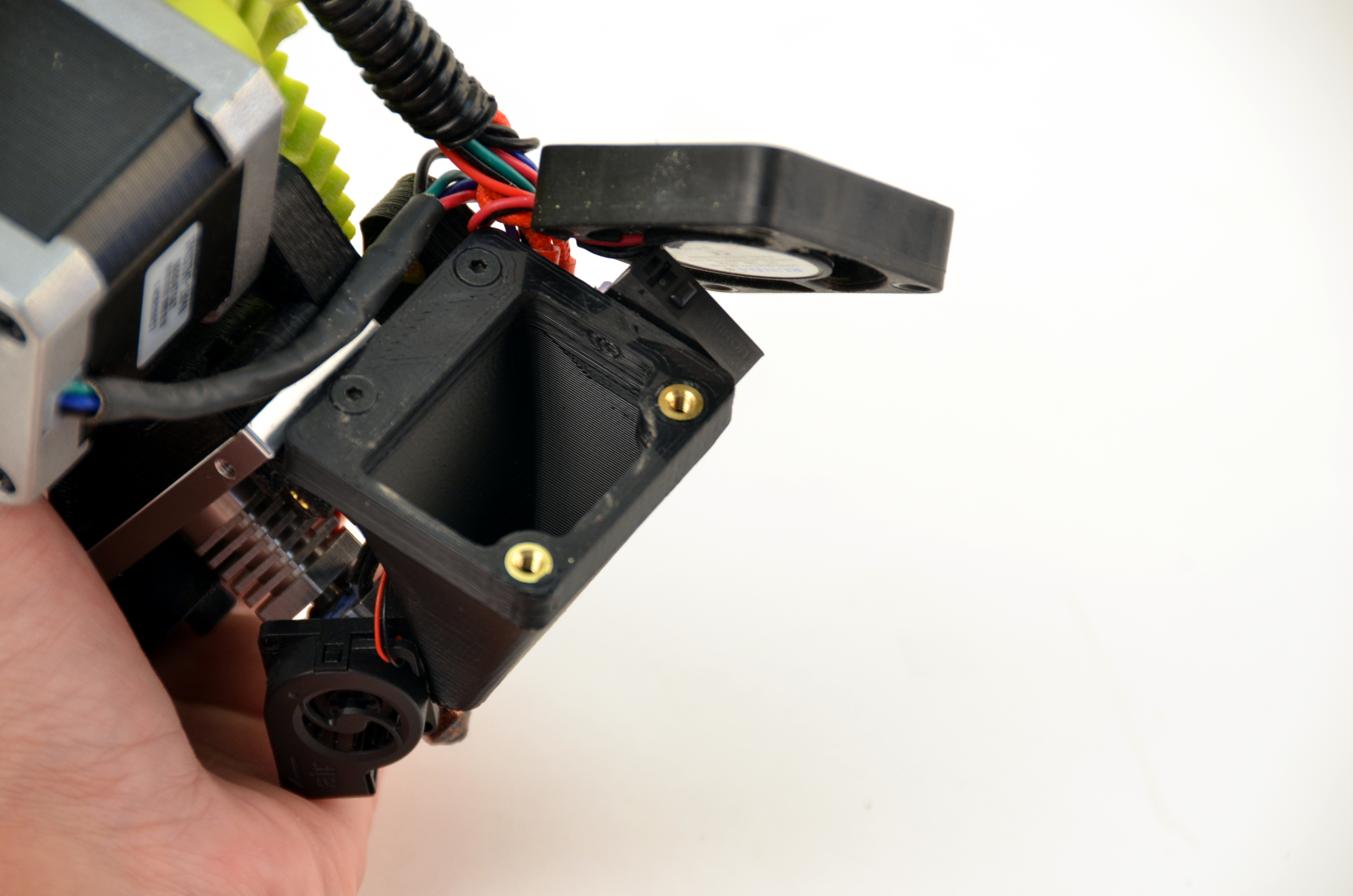
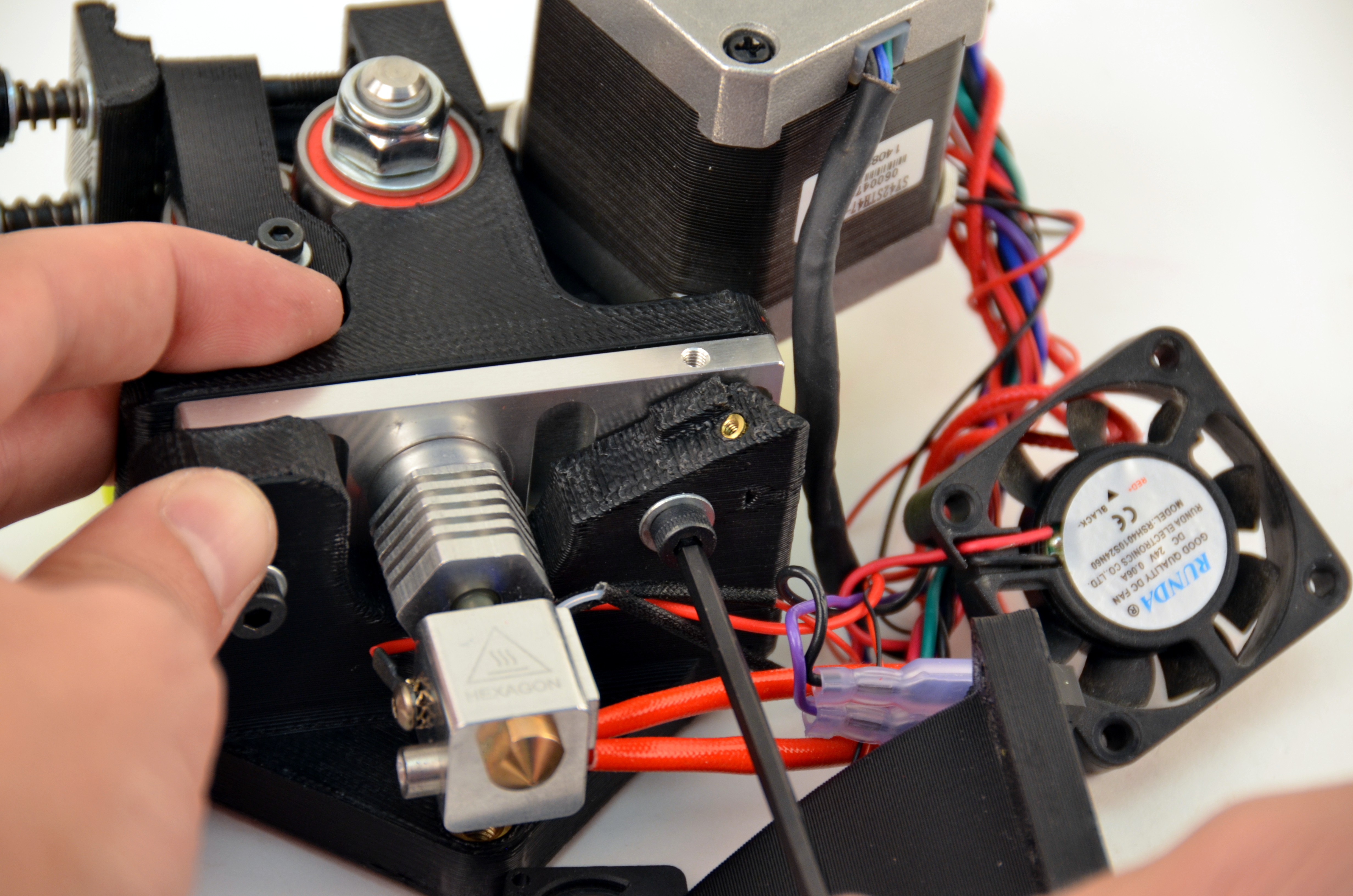
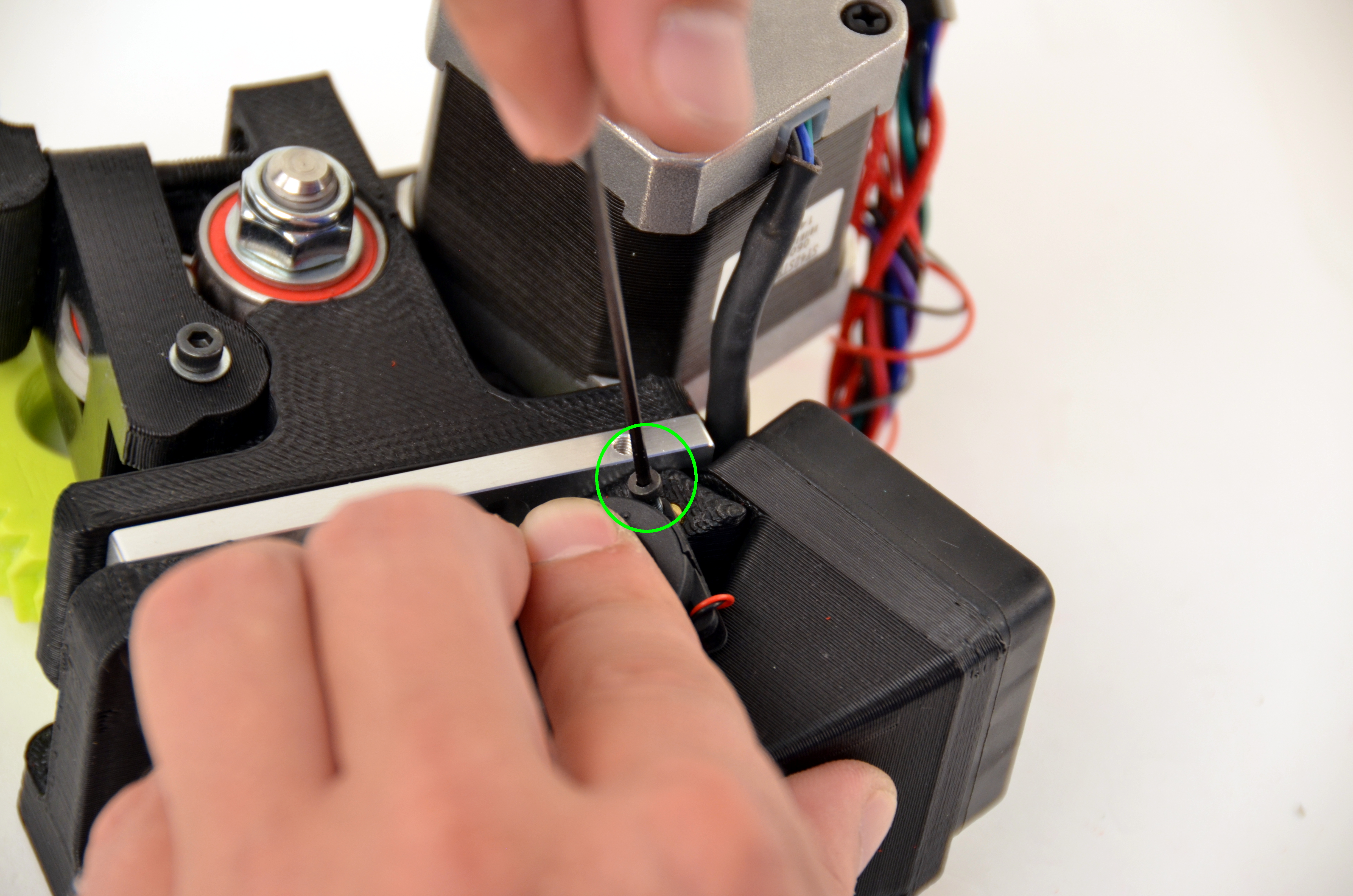
Using your 2mm driver, remove the screws holding the fan mount to the tool head mount.
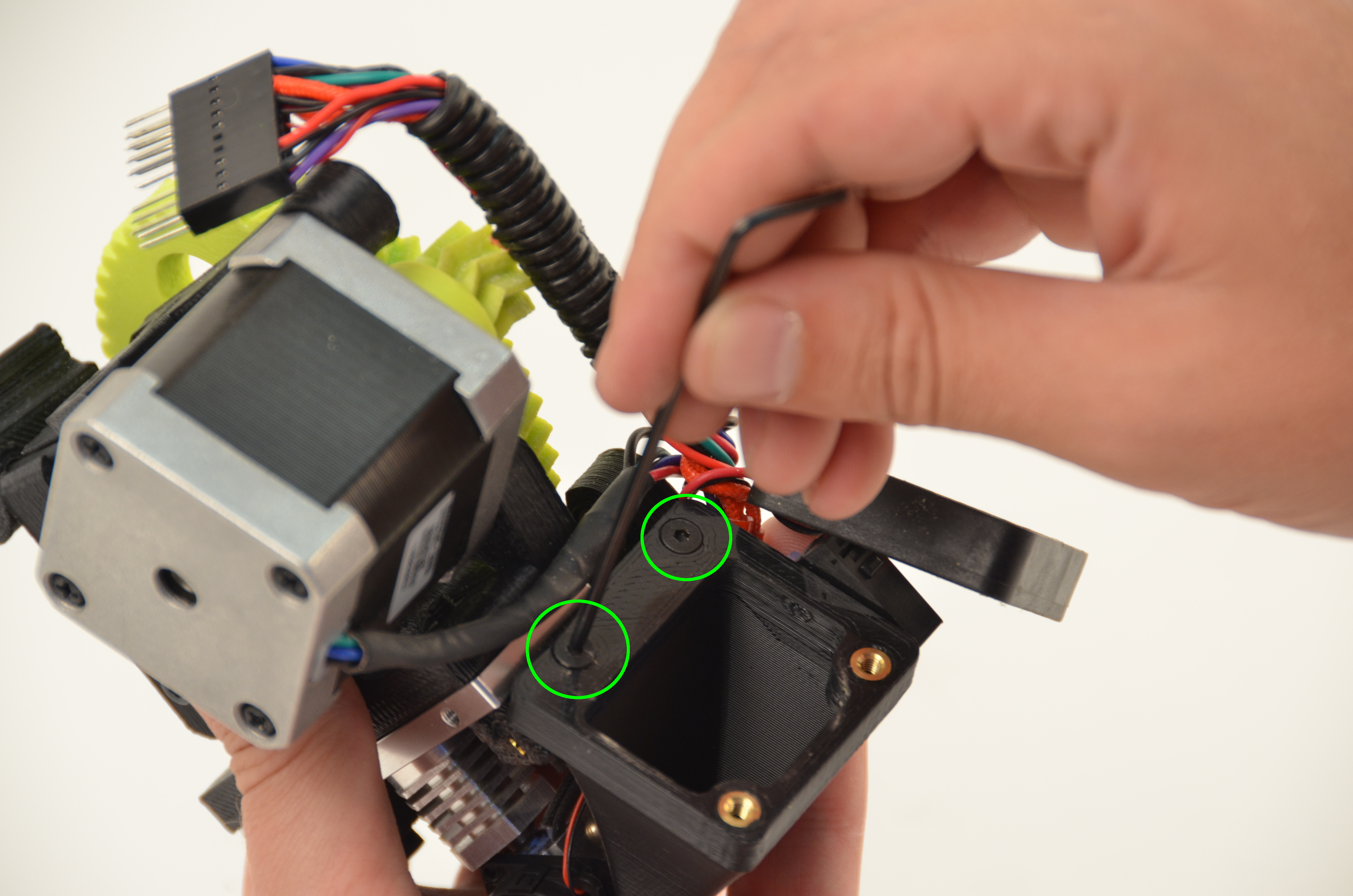
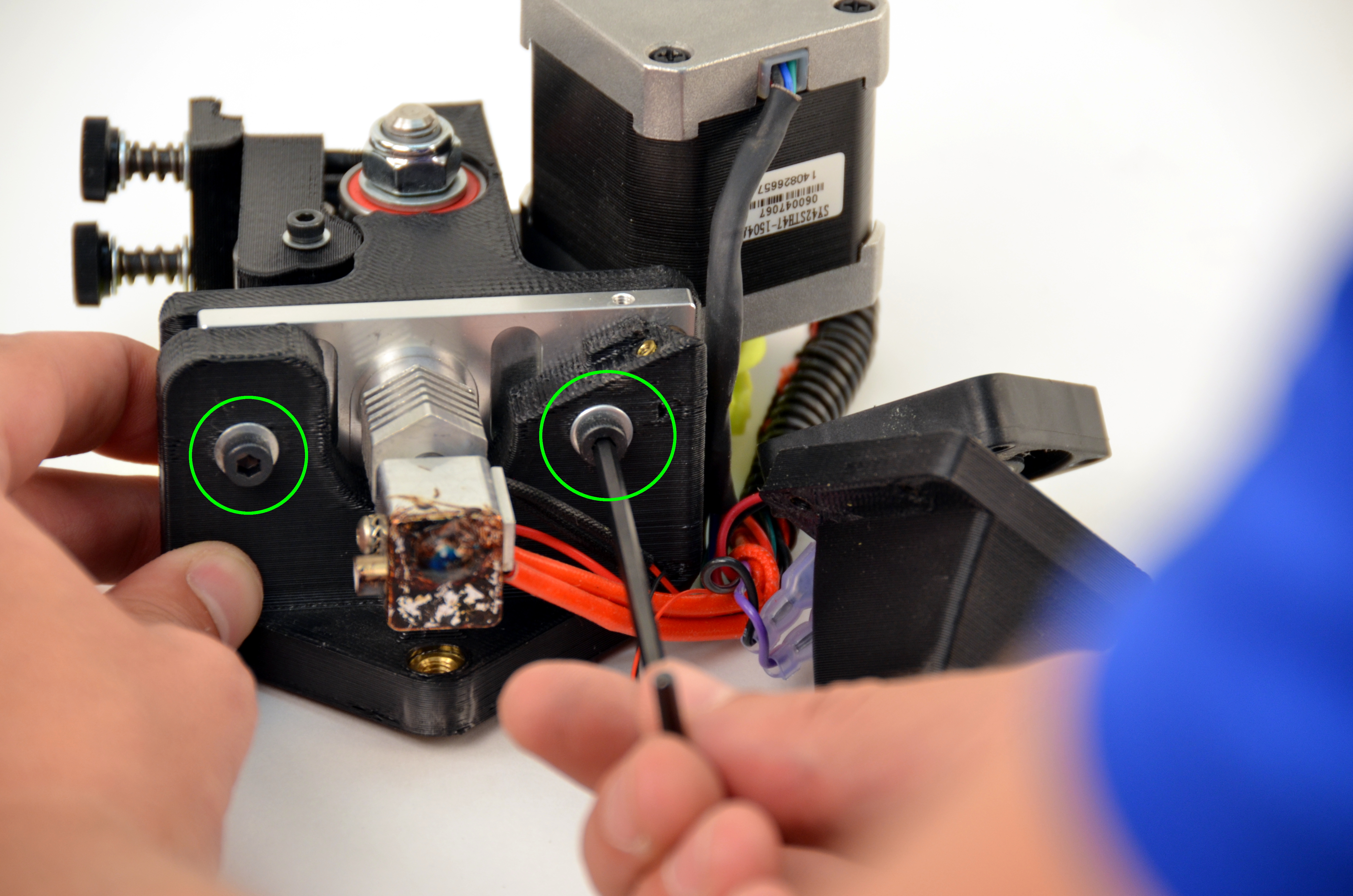
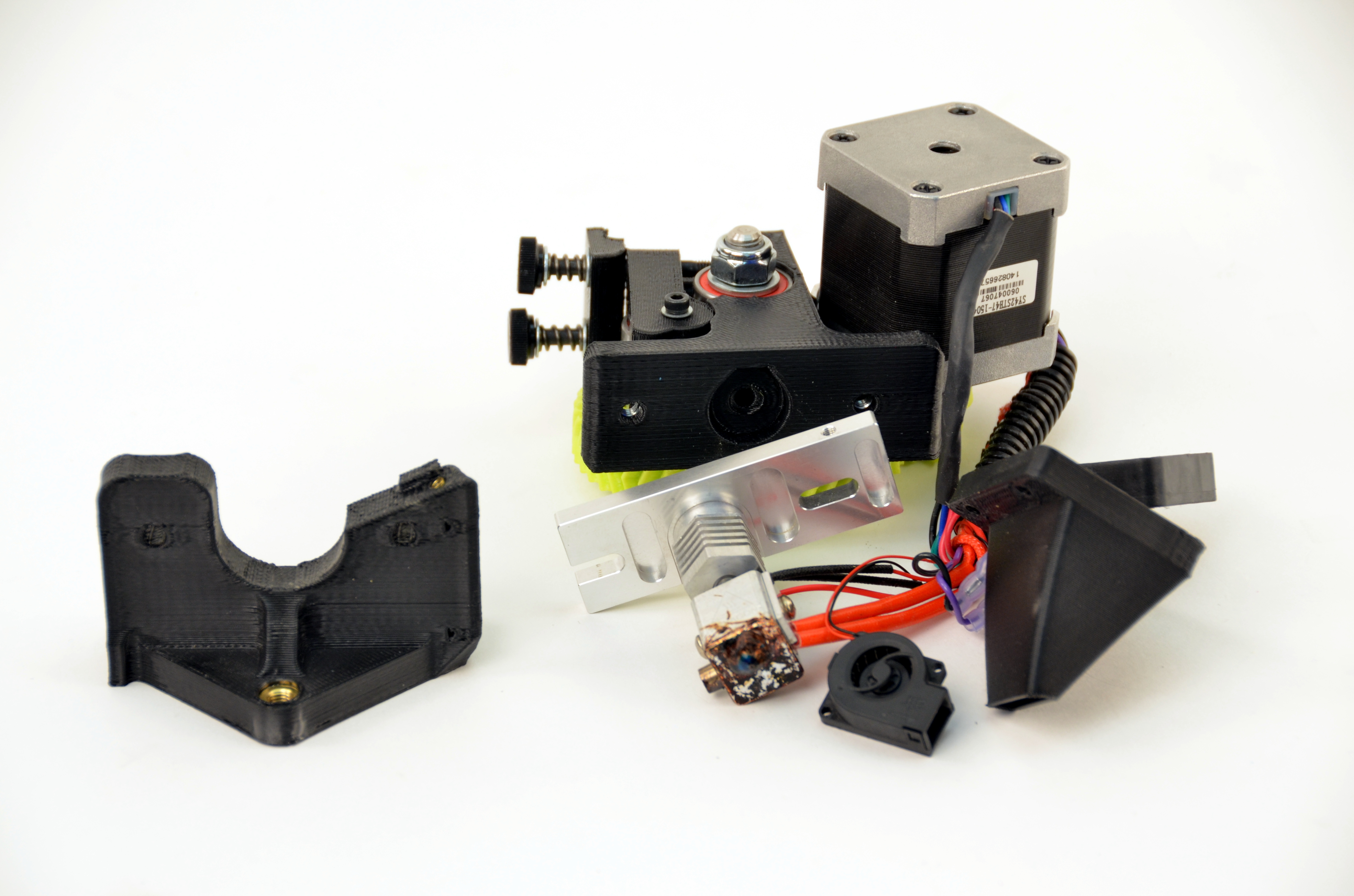
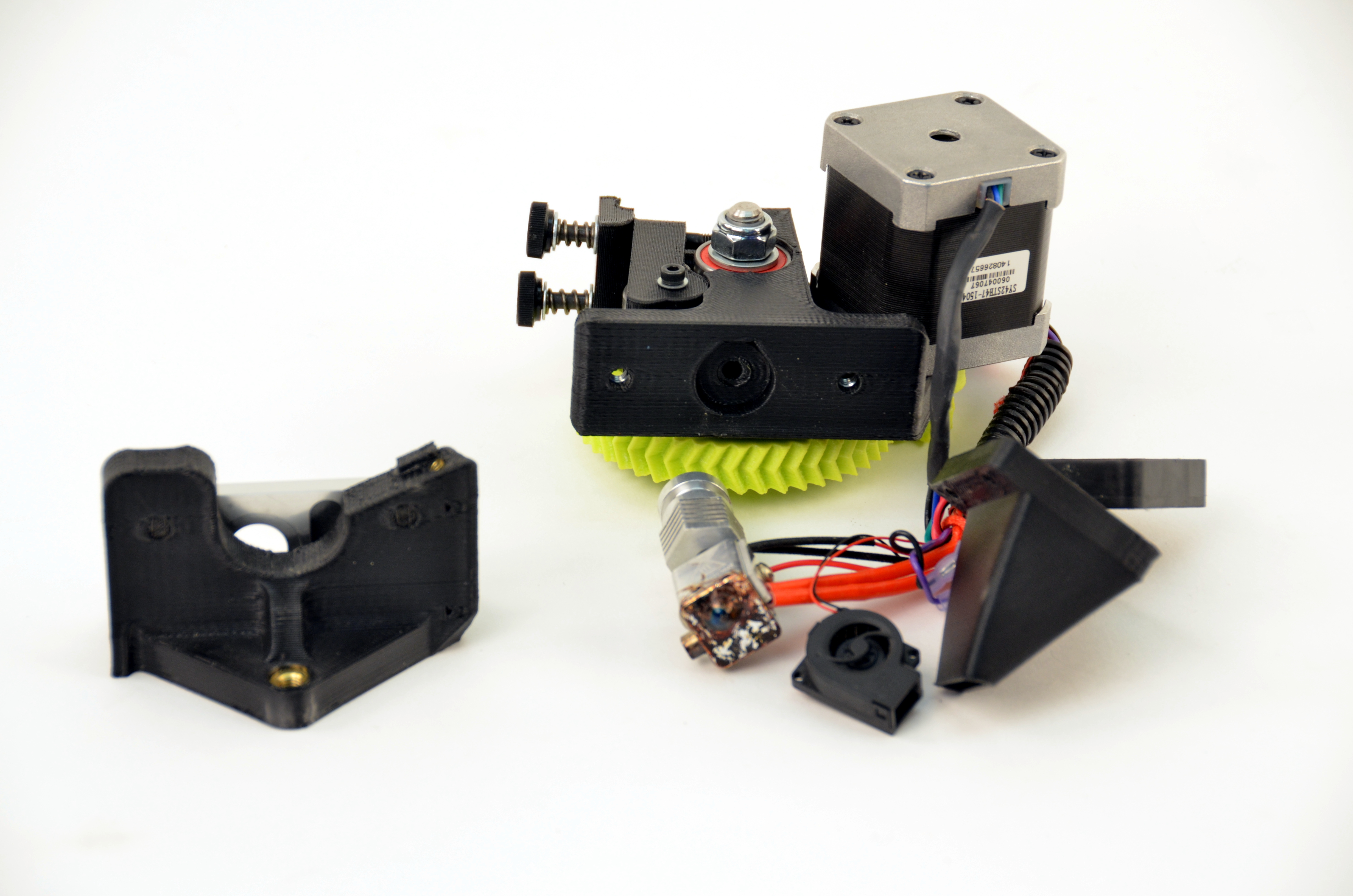
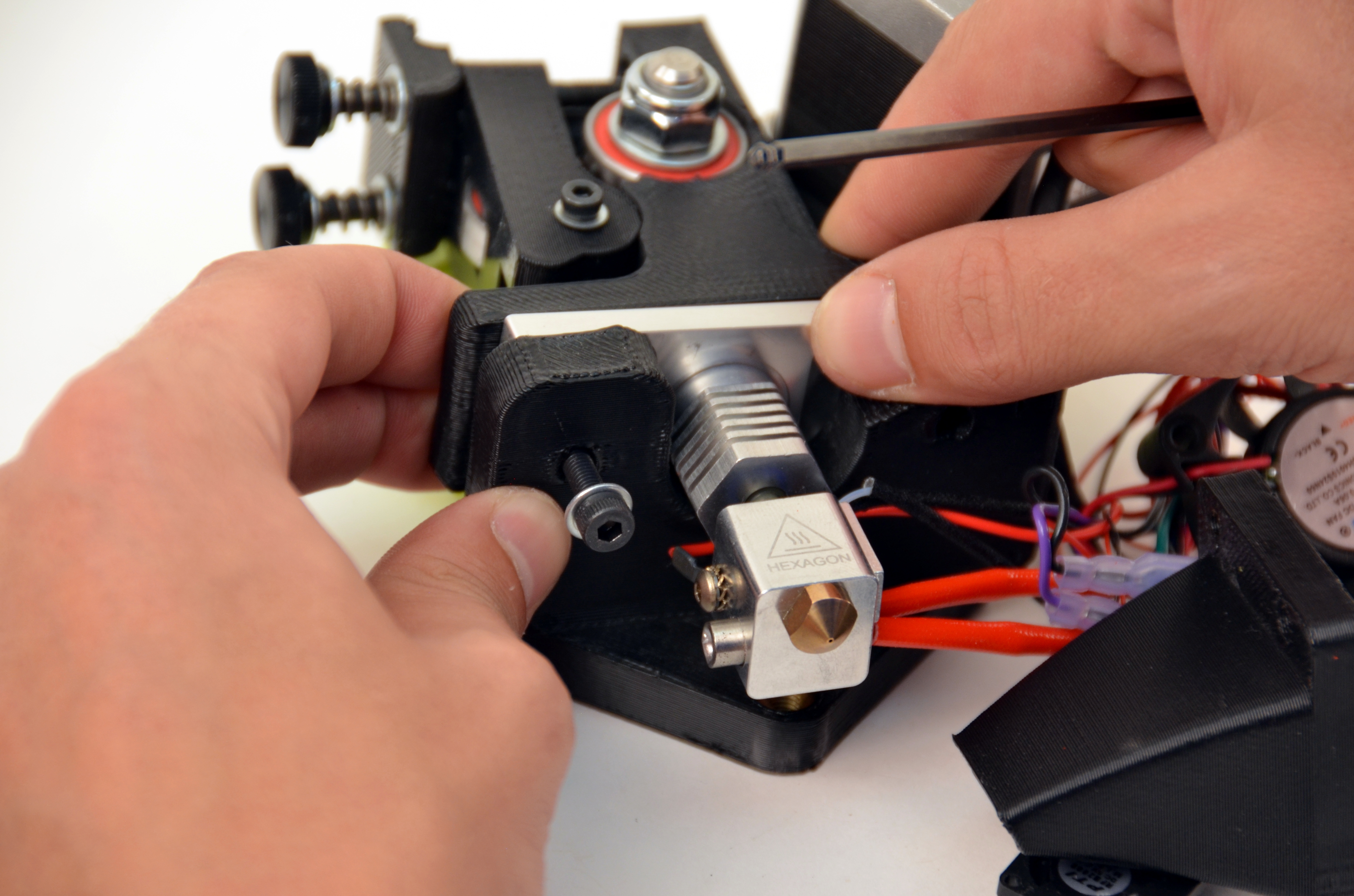
Using your 3mm driver, remove the two screws holding the hot end from the extruder assembly.
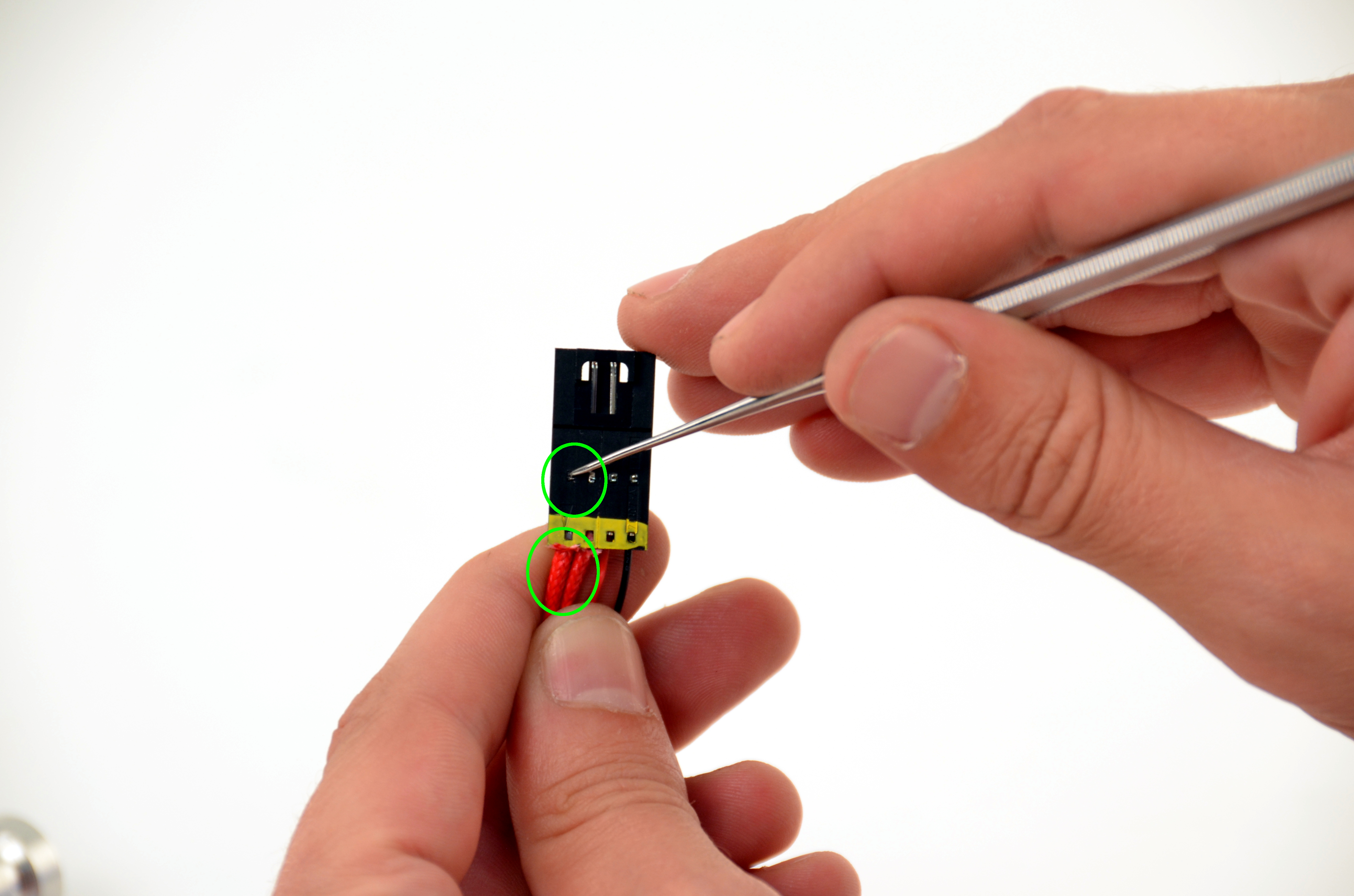
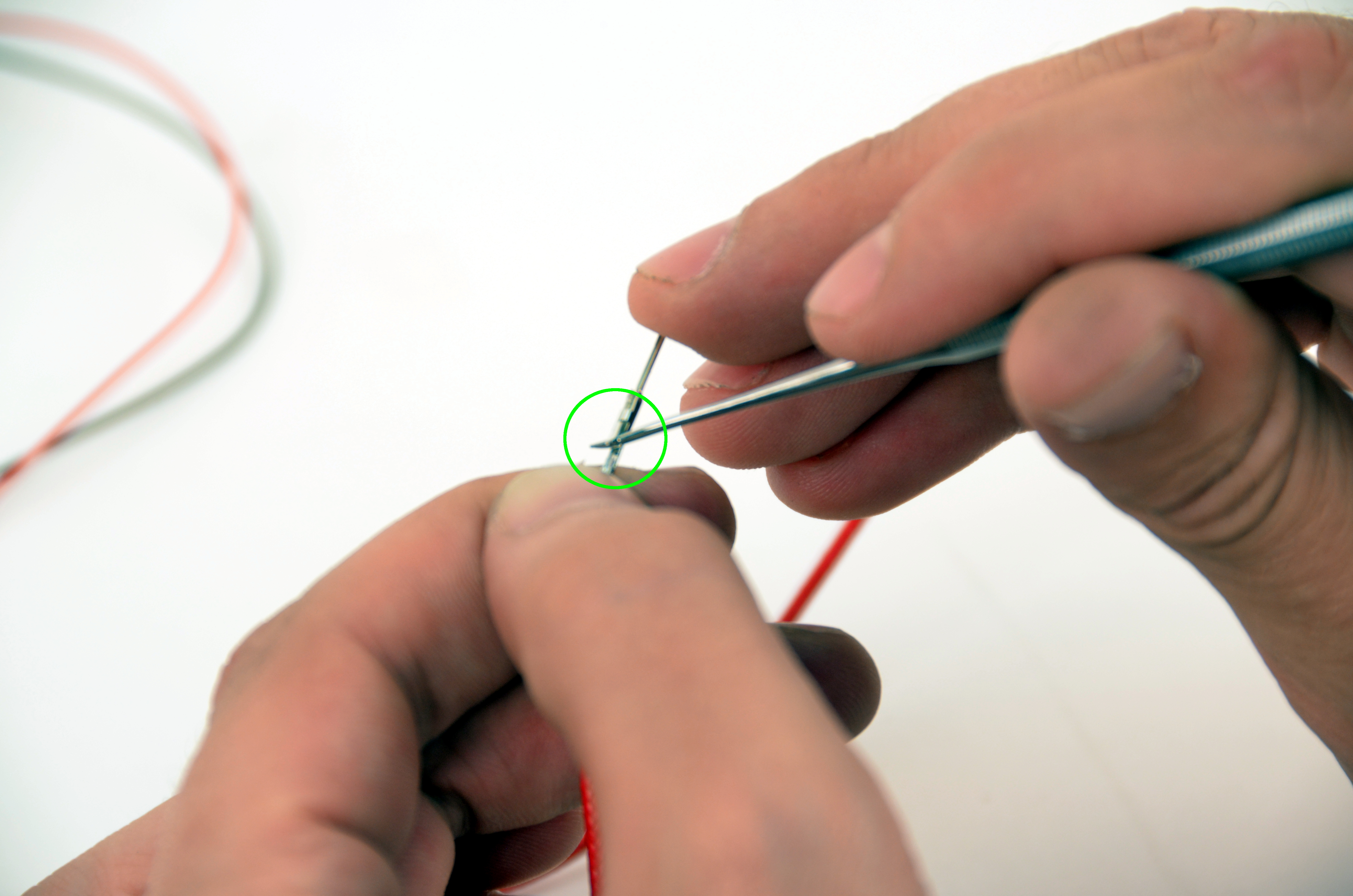
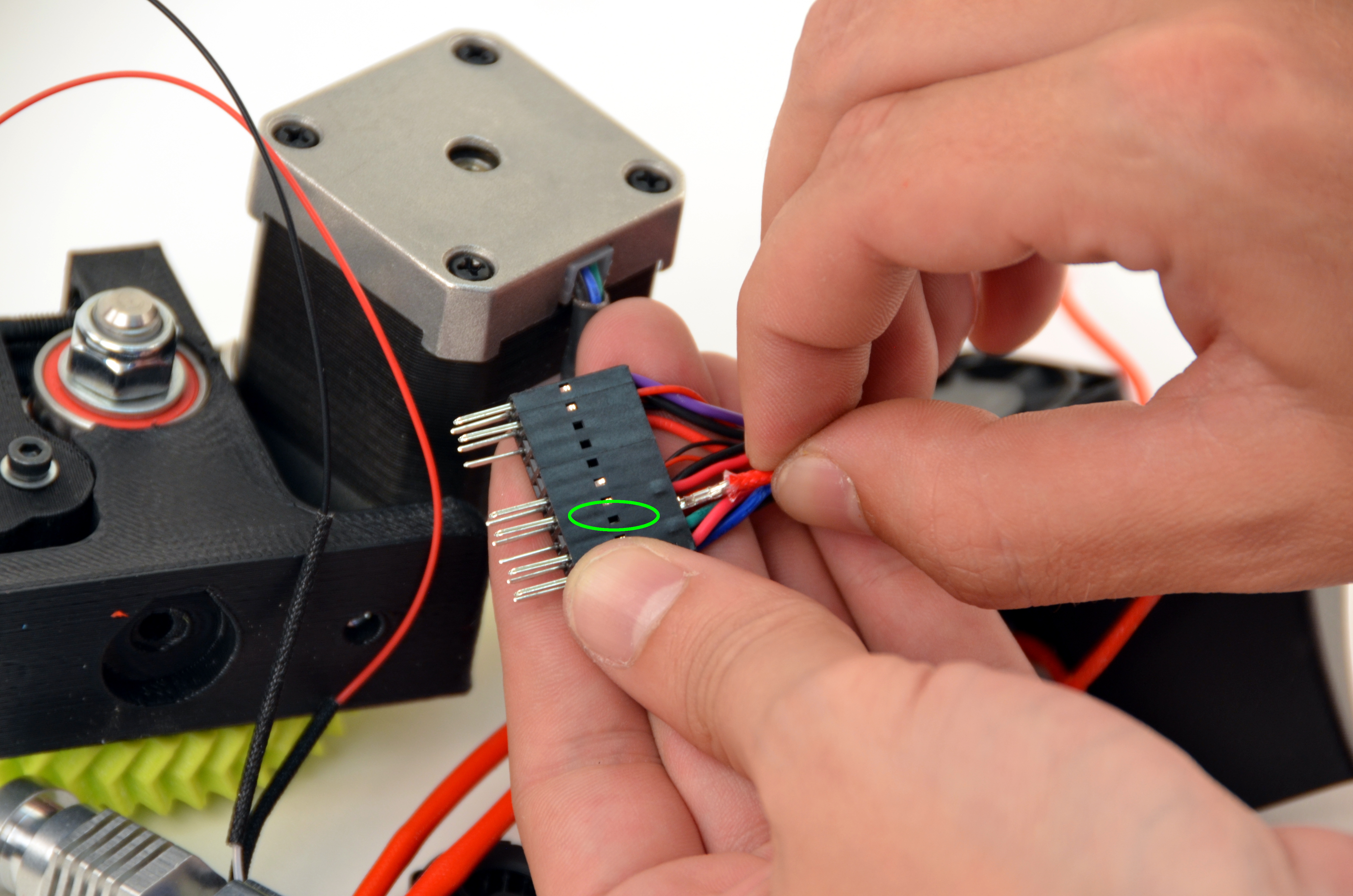
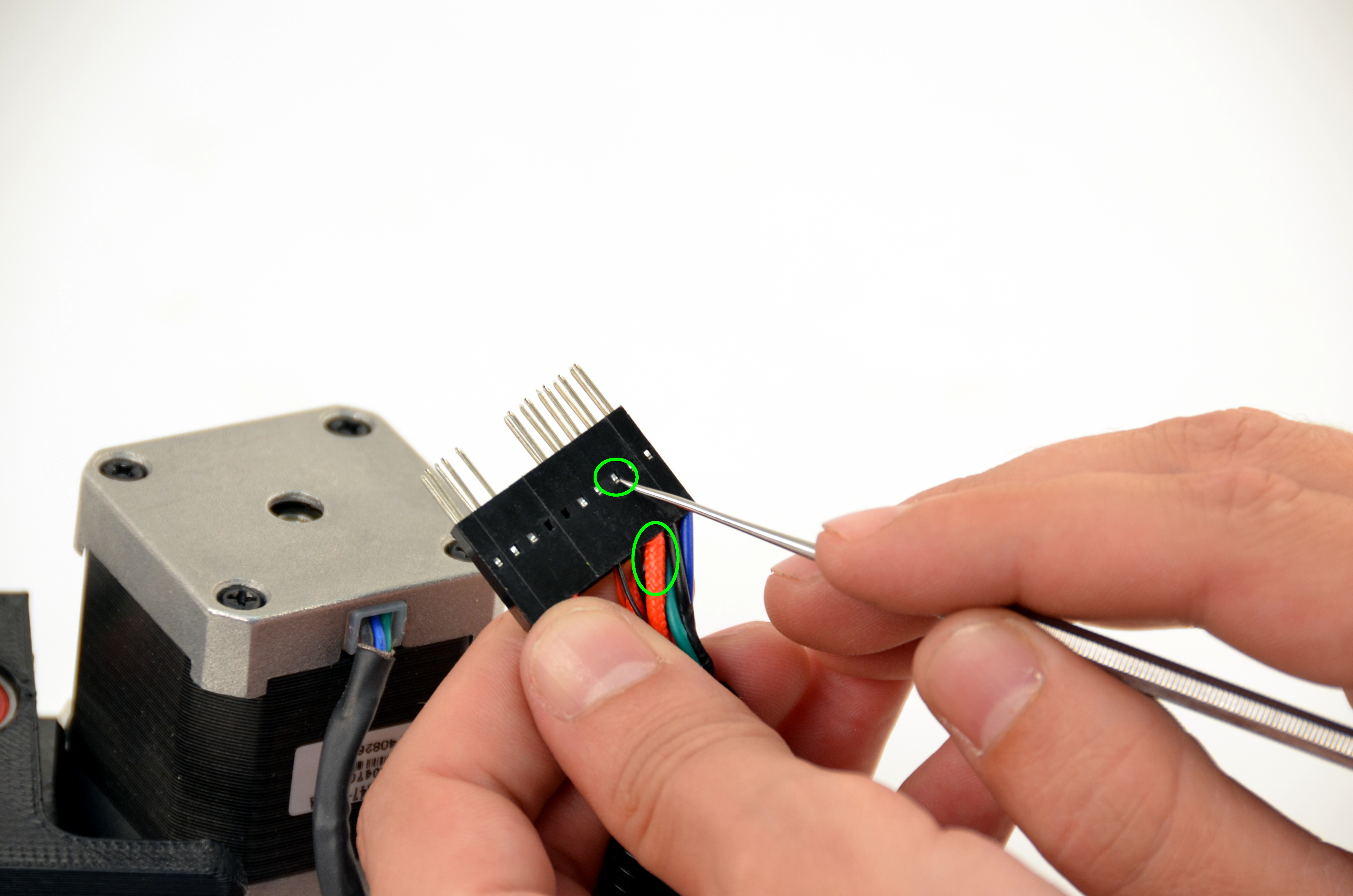
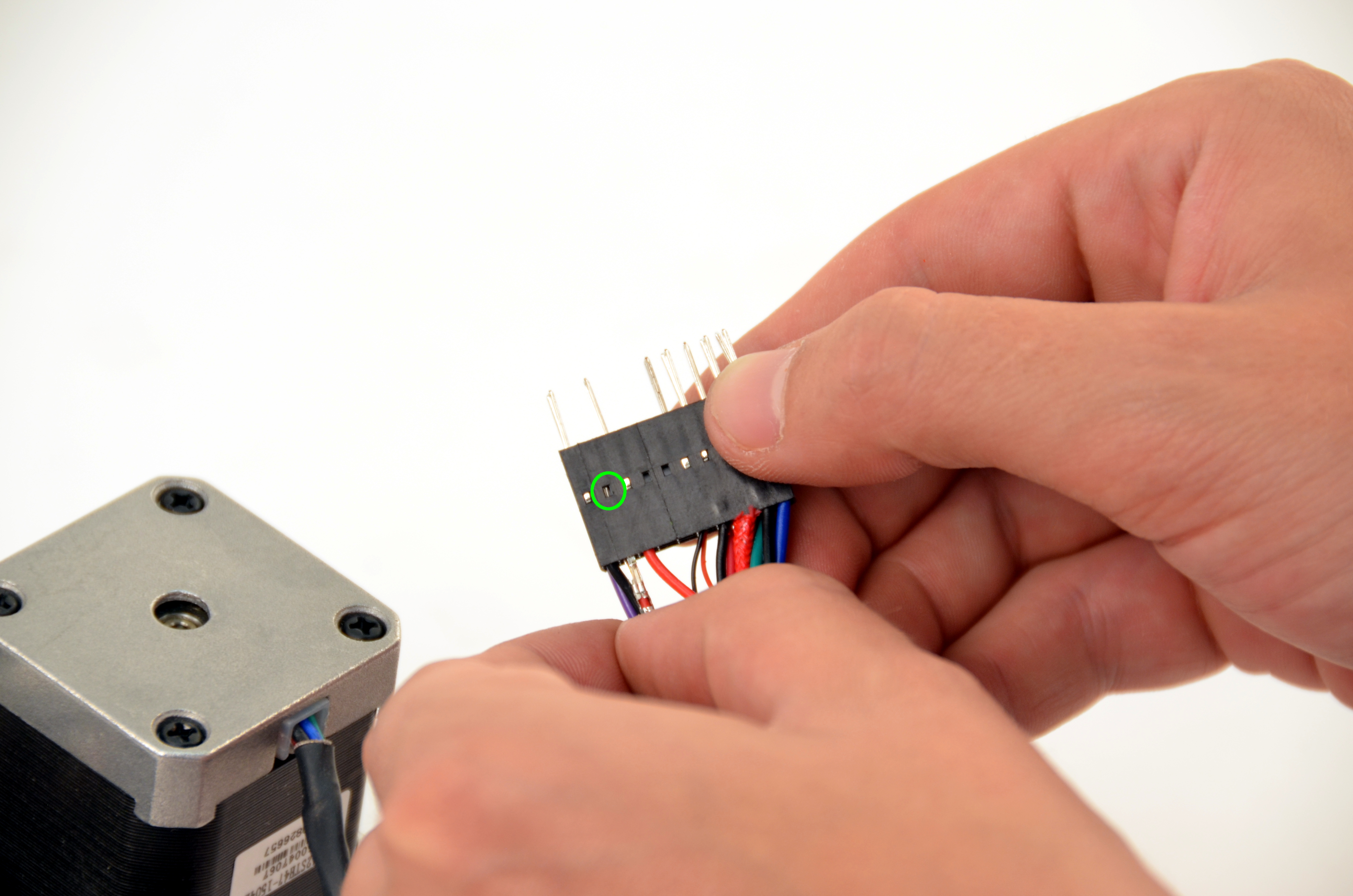
Using the dental pick included with your toolkit, gently push down on the clasp that holds the pin in place. This will allow you to remove the pins.
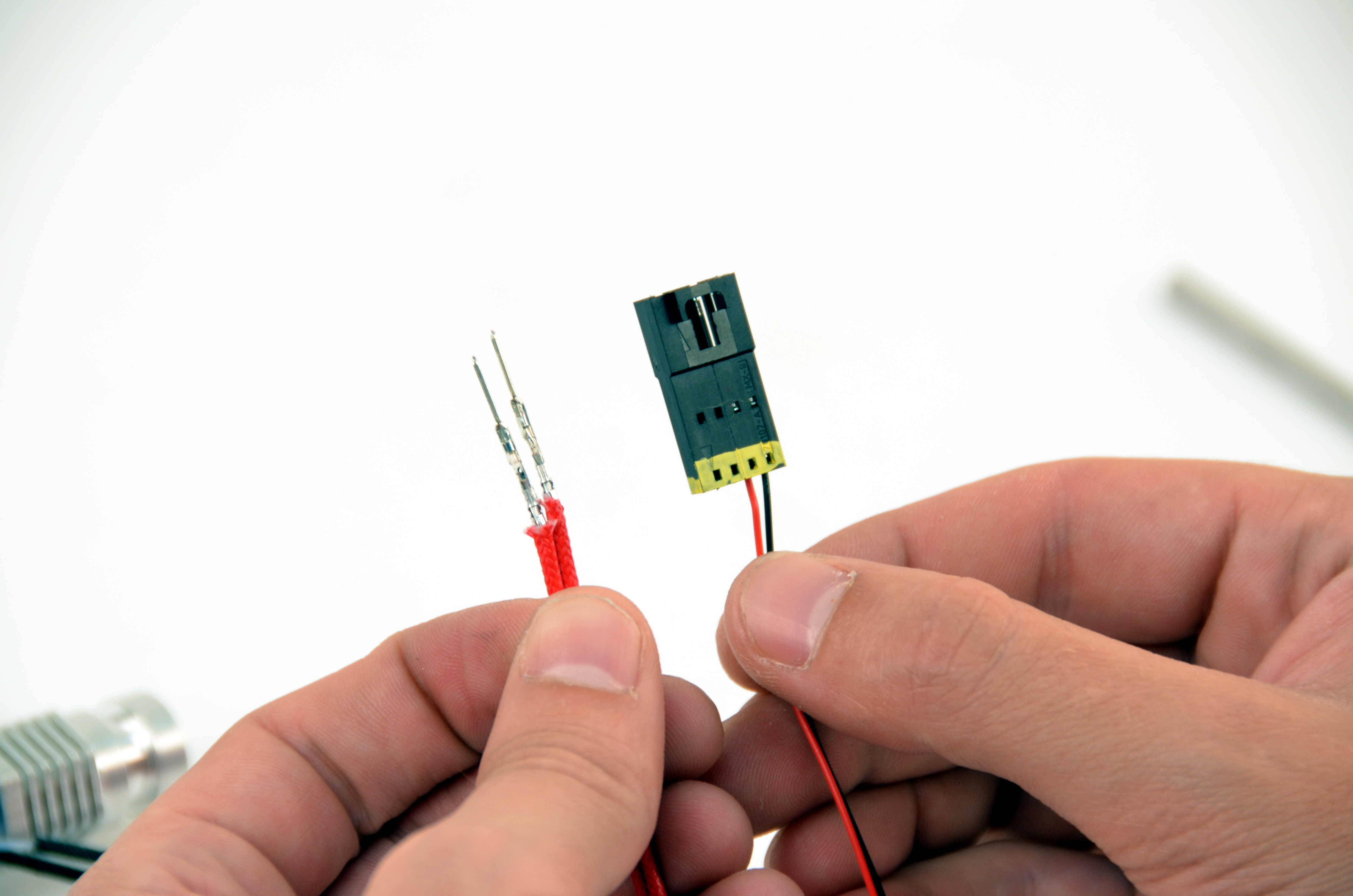
Release and remove the two large red wires.
The pick is sharp. Be careful.
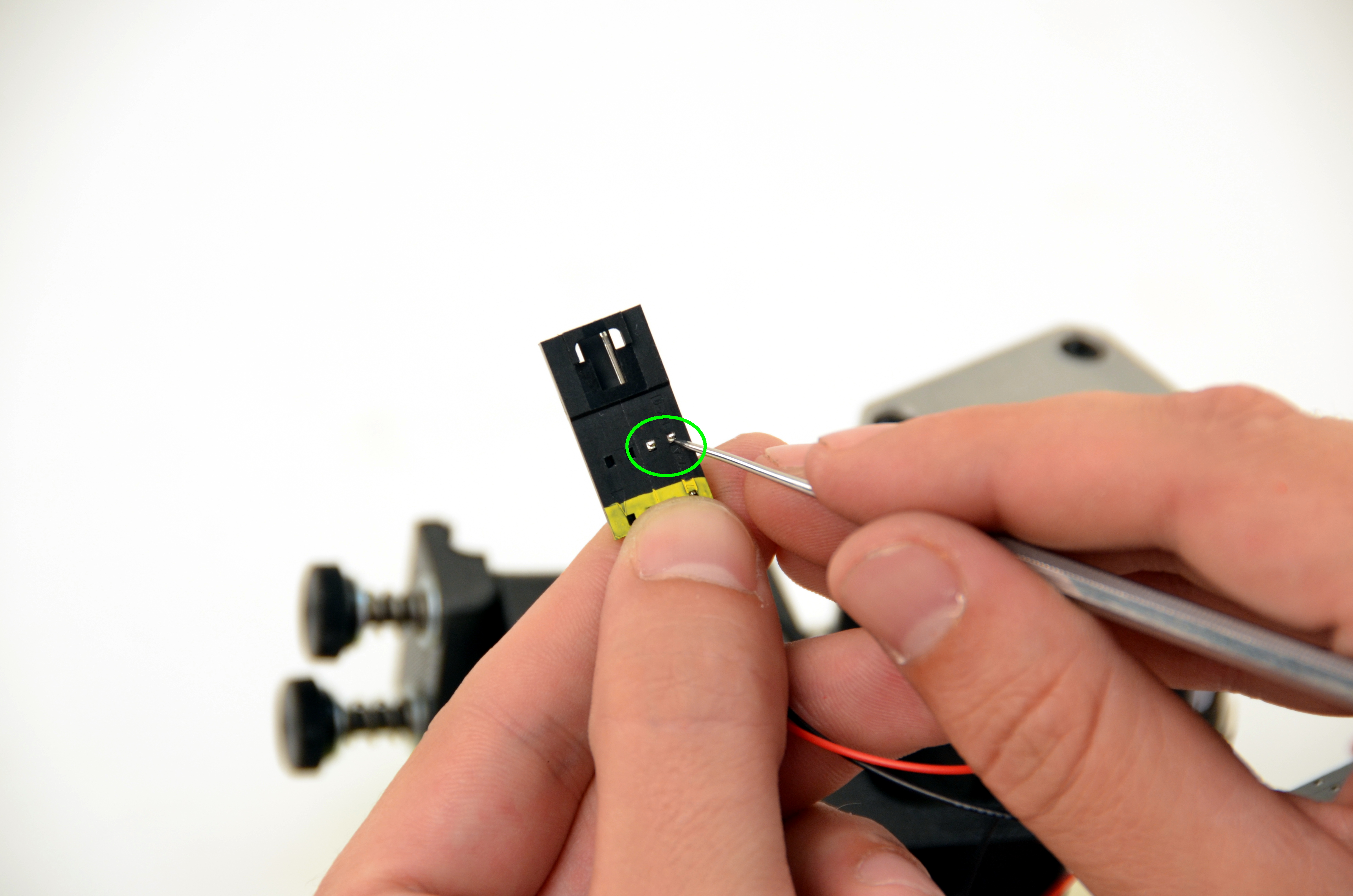
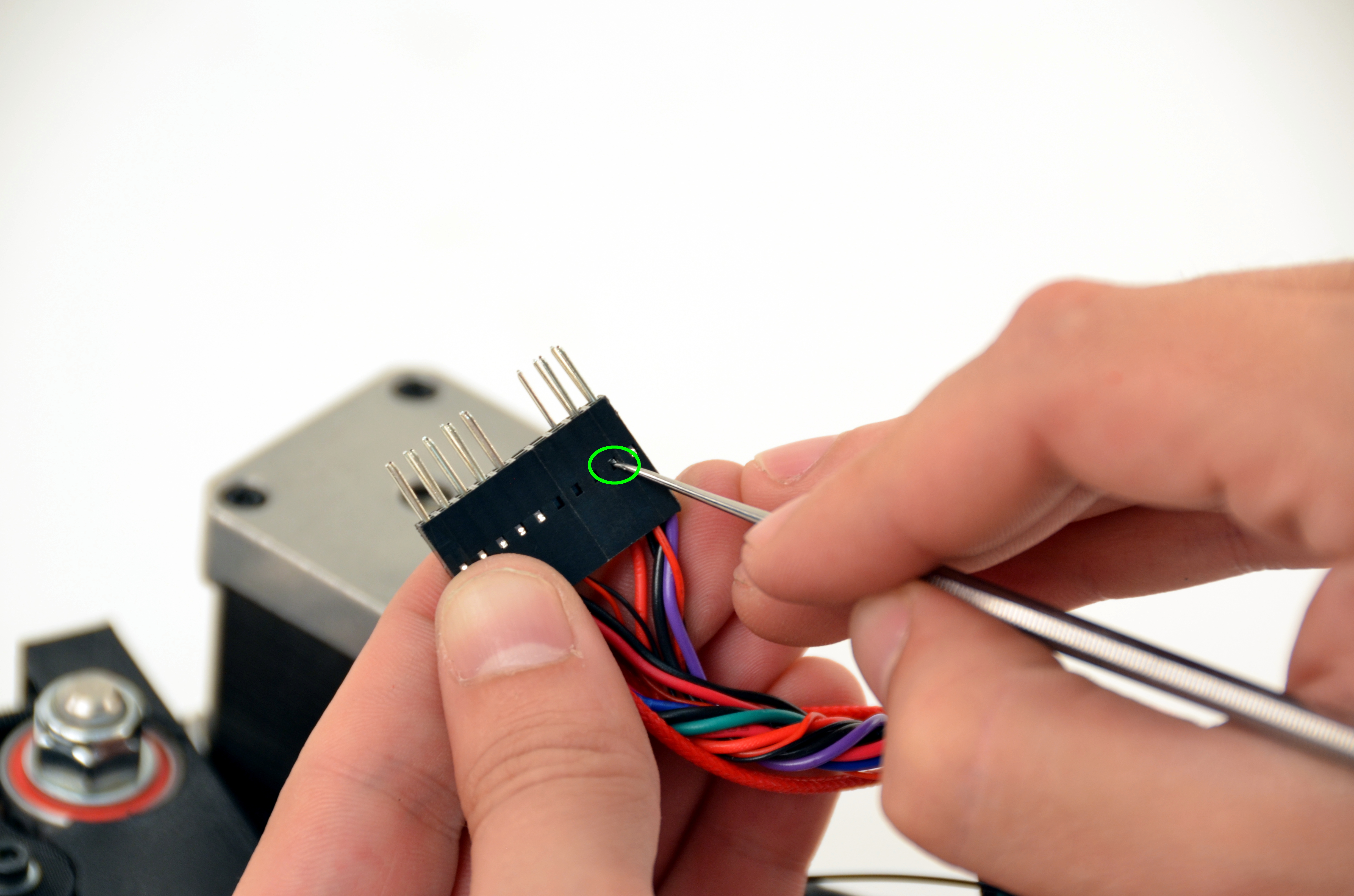
Using your dental pick, gently raise the catch that was depressed in the previous step.
The pick is sharp. Be careful.
Remove the cable housing for wire routing access.

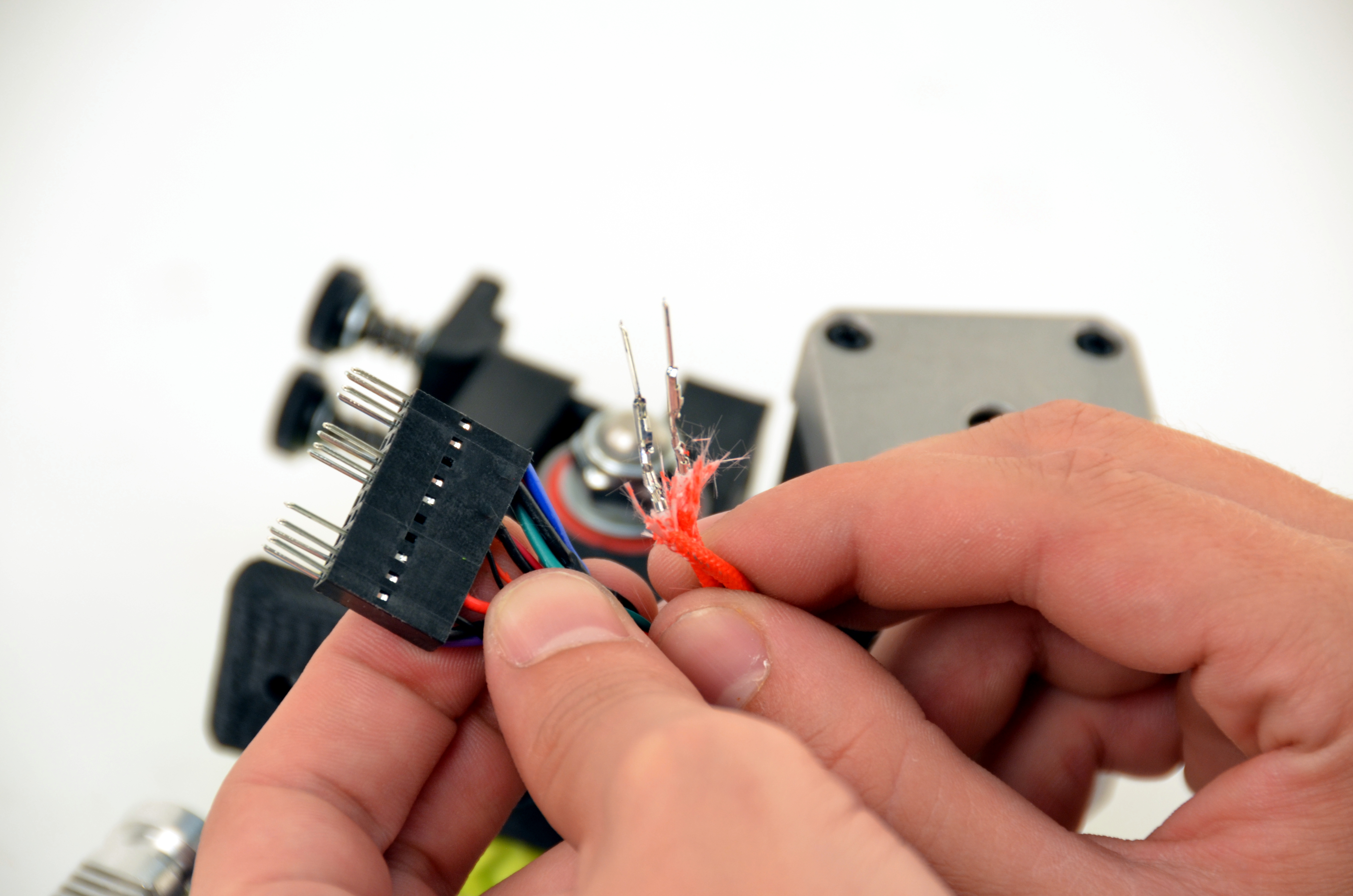
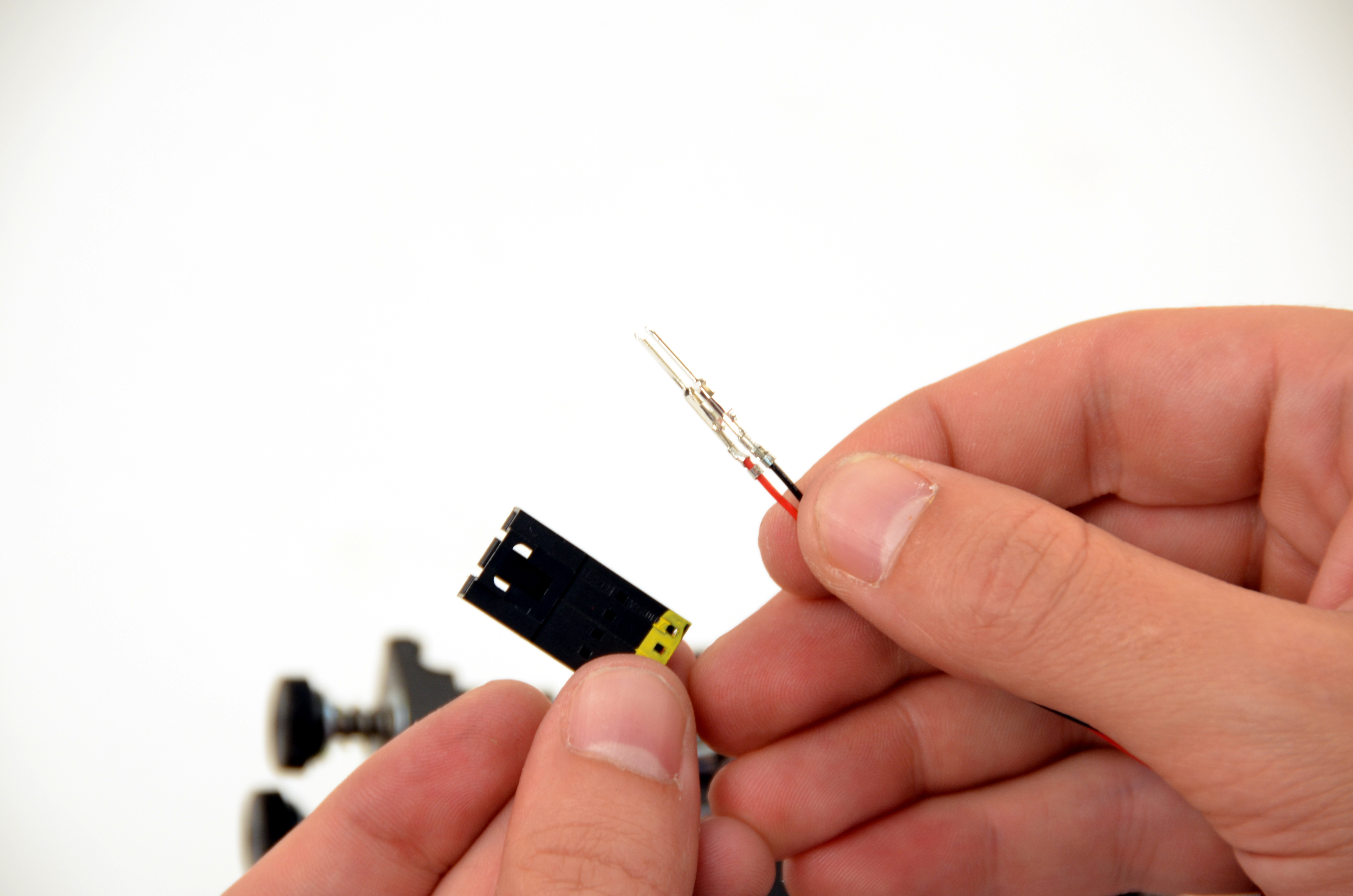
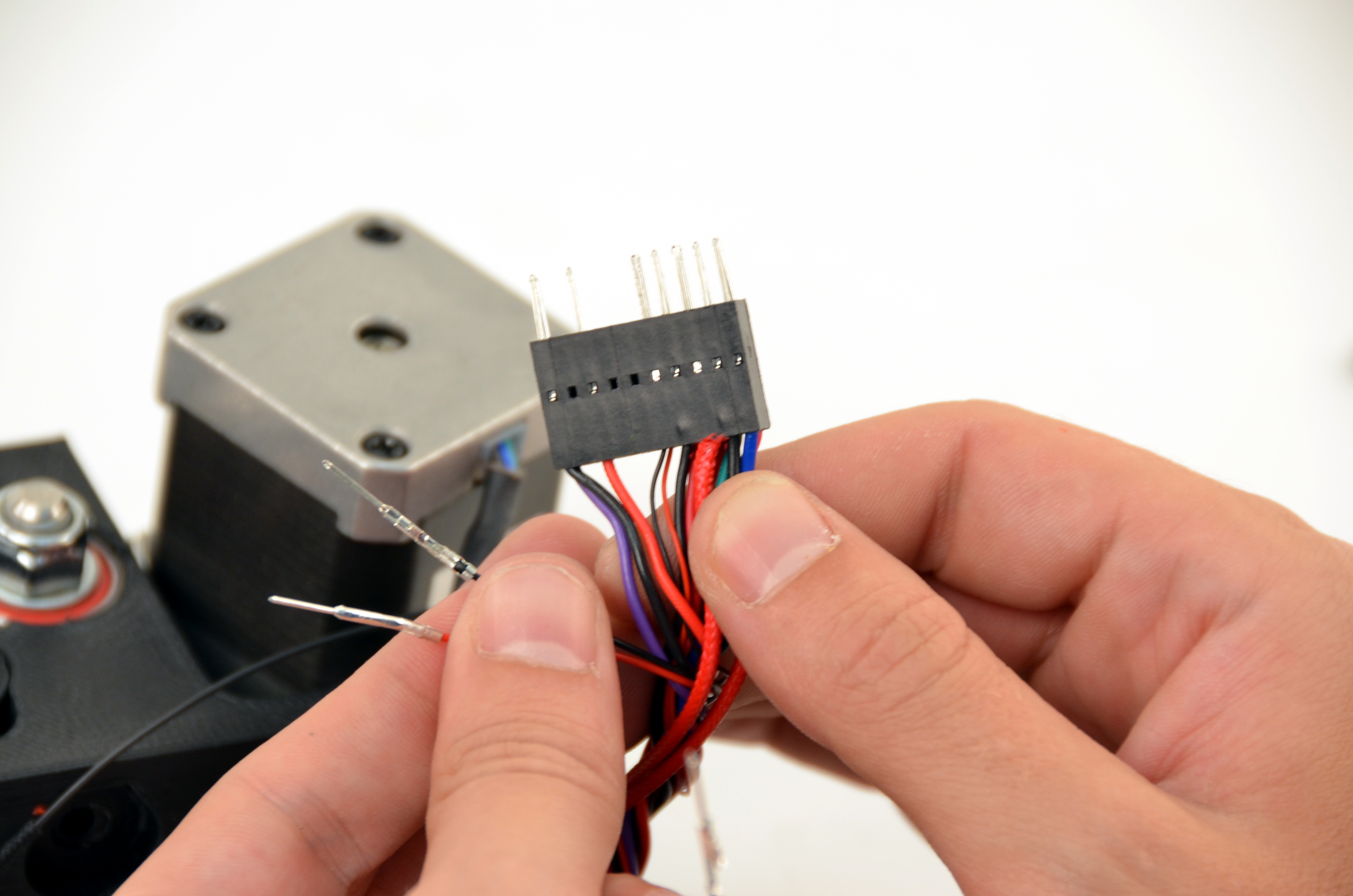
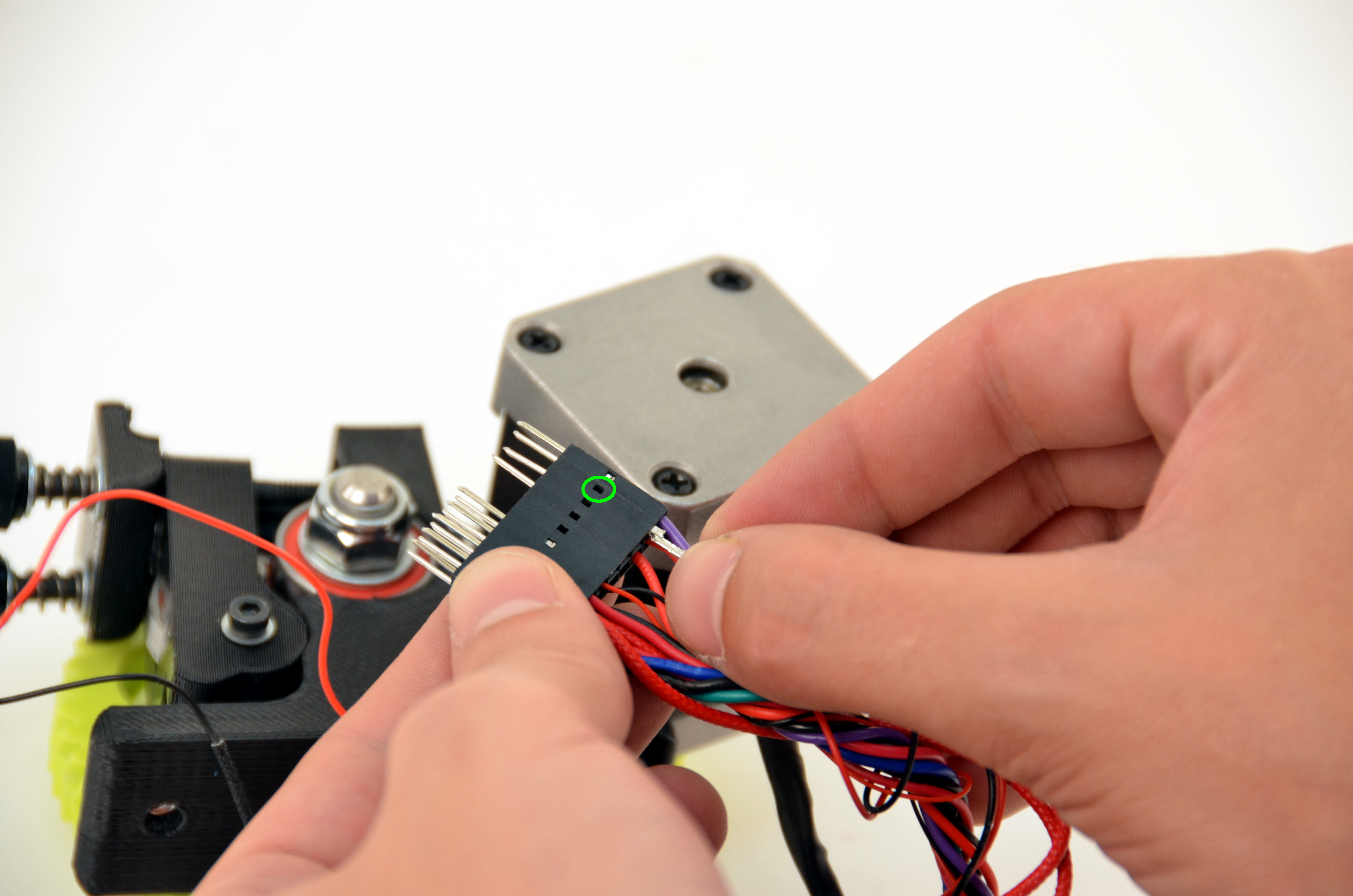
Using the dental pick included with your toolkit, gently push down on the catch that holds the pin in place. This will allow you to remove the existing pins.
Release and remove the two larger red wires.
The pick is sharp. Be careful.

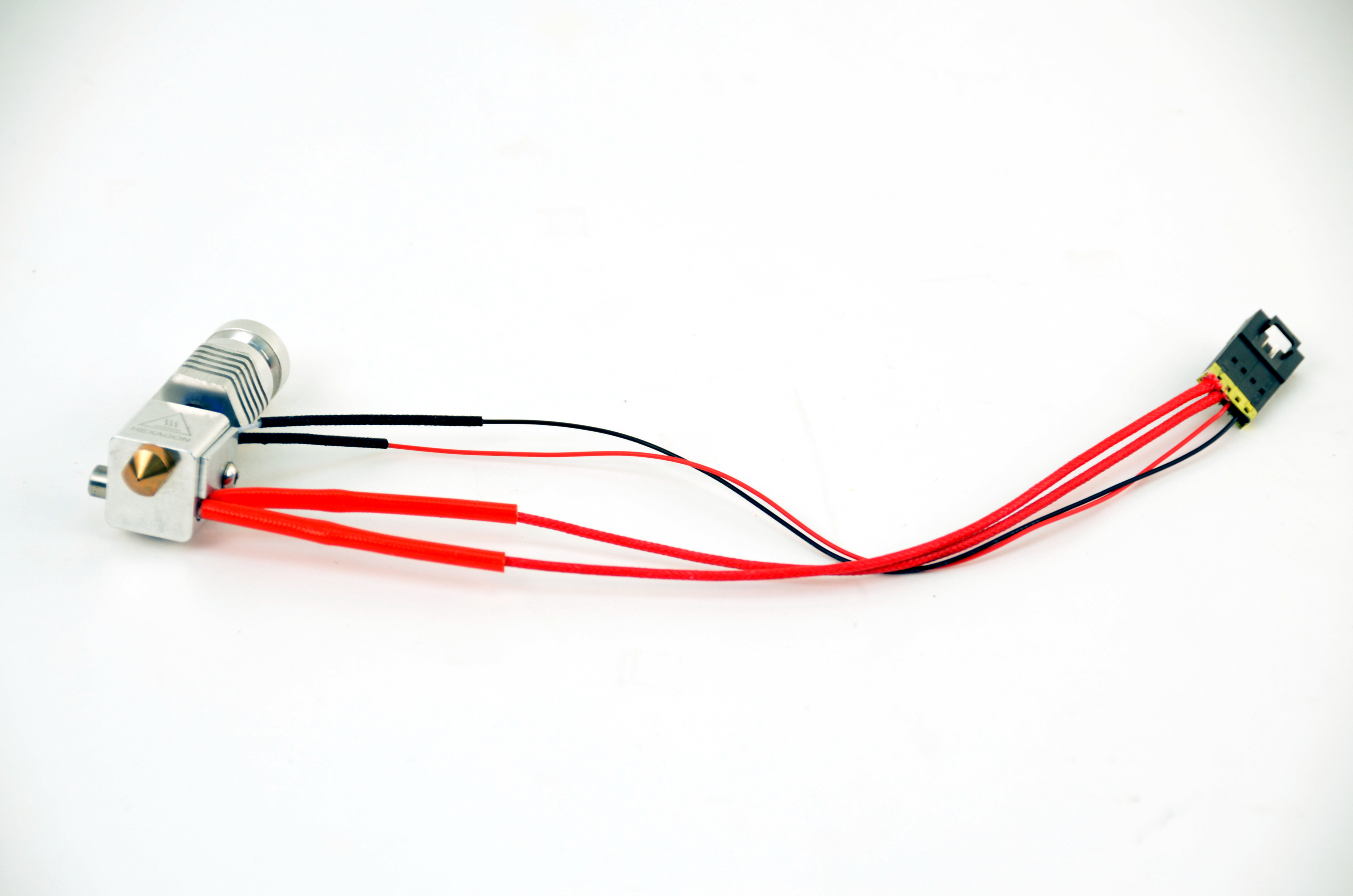
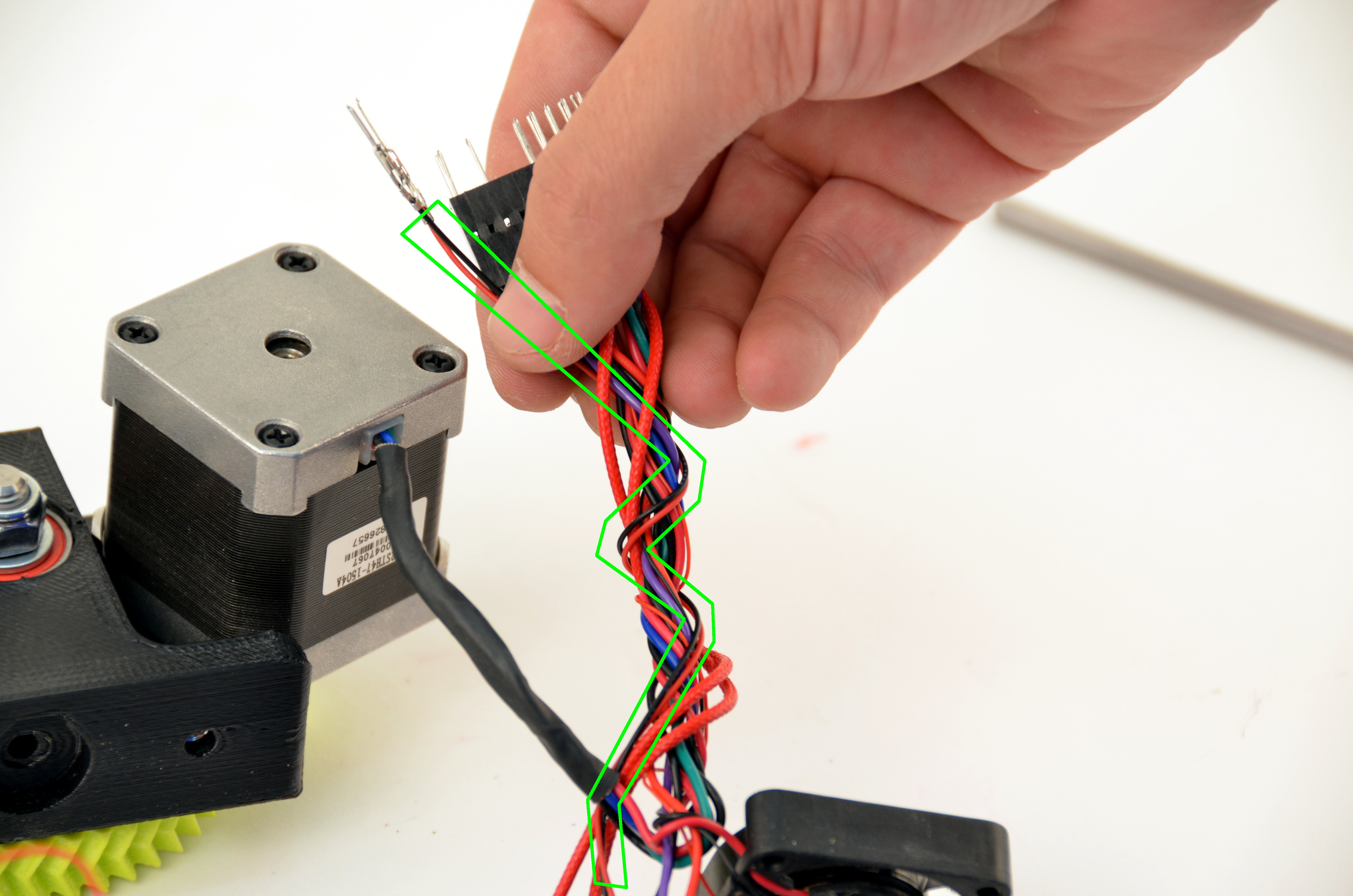
The LulzBot Hexagon Hot End comes with standard length wires.
You will be required to wrap the two heater cartridge wires around the existing wiring harness twice to reduce the wire length.
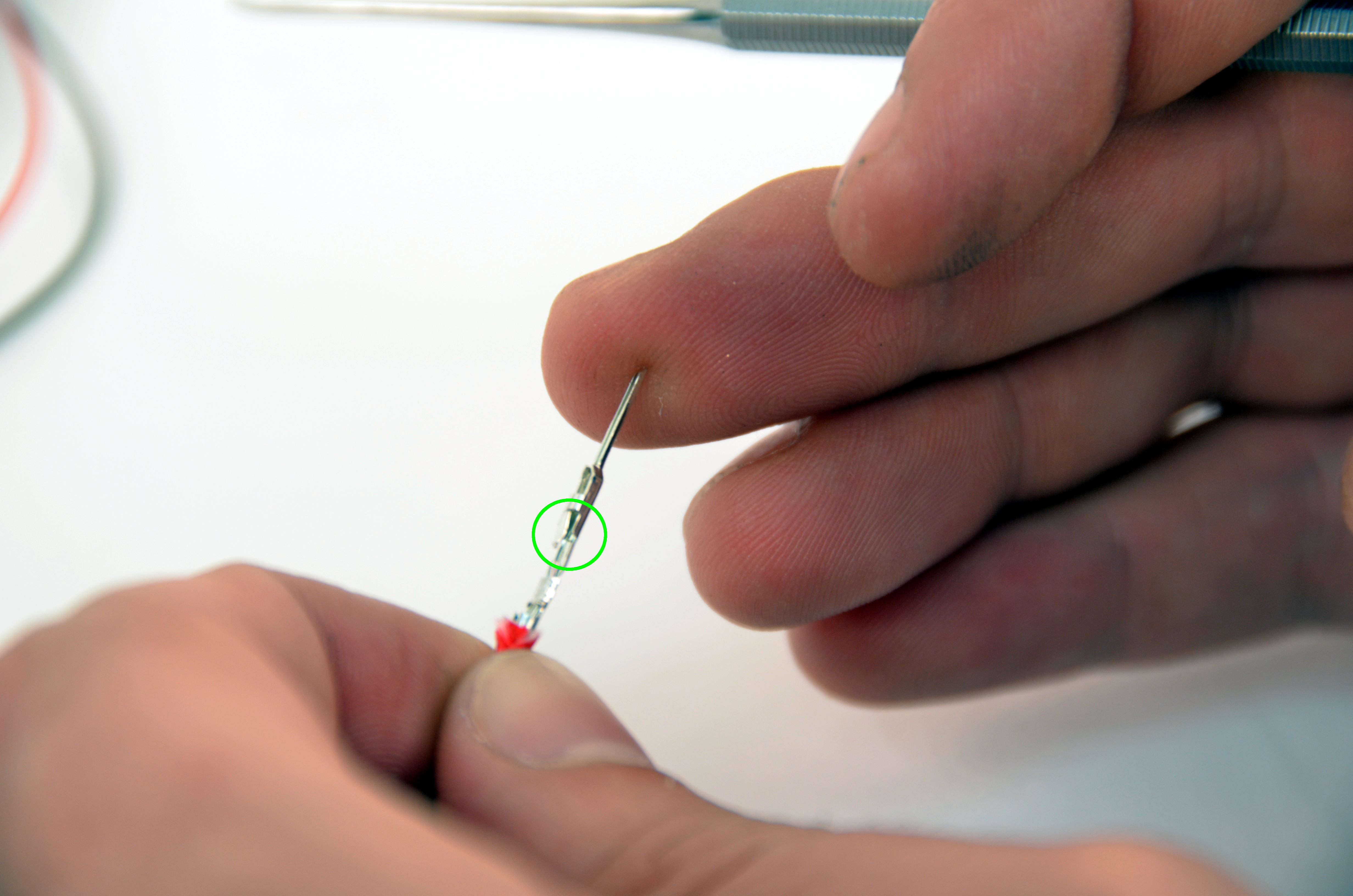
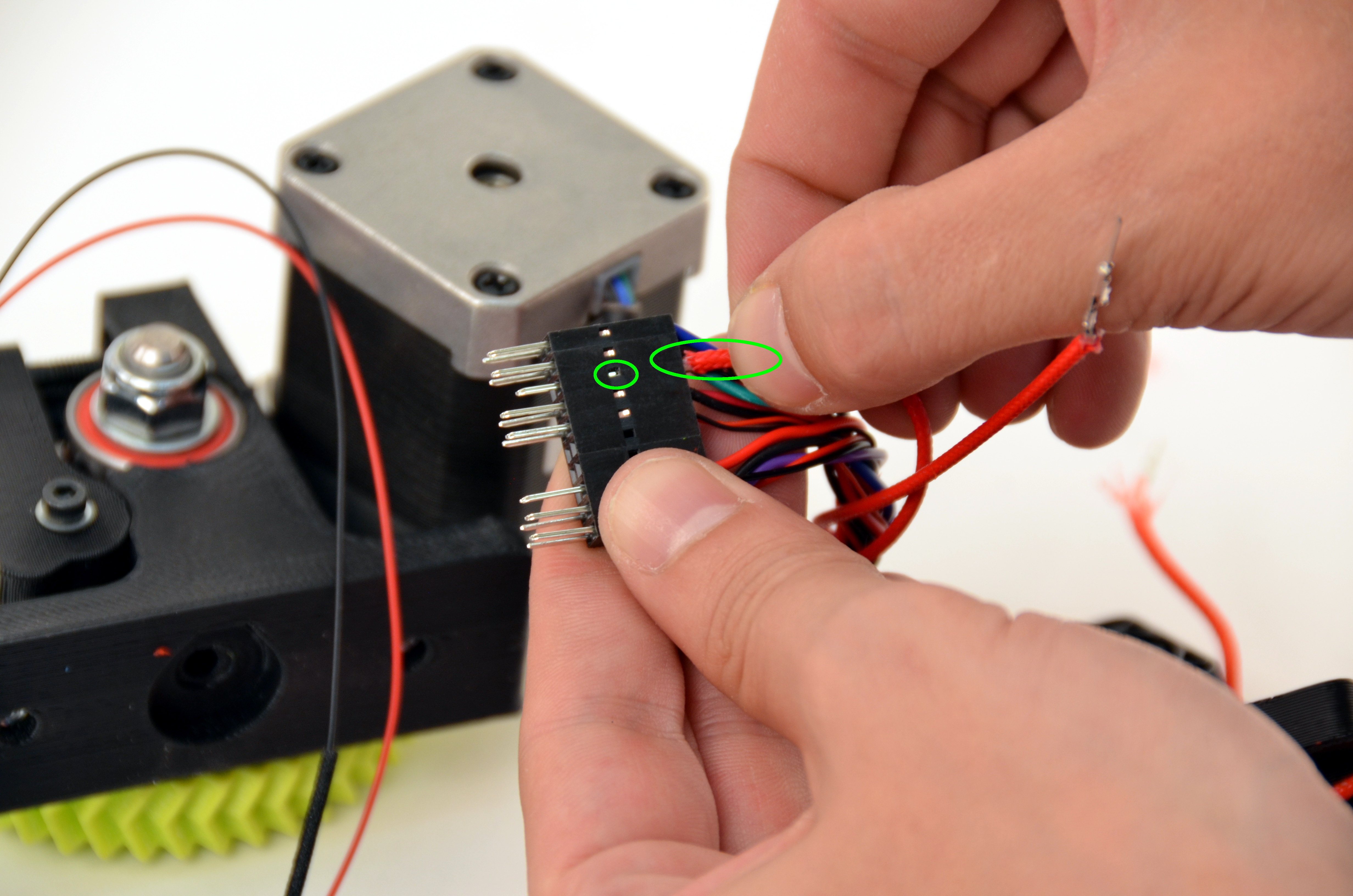
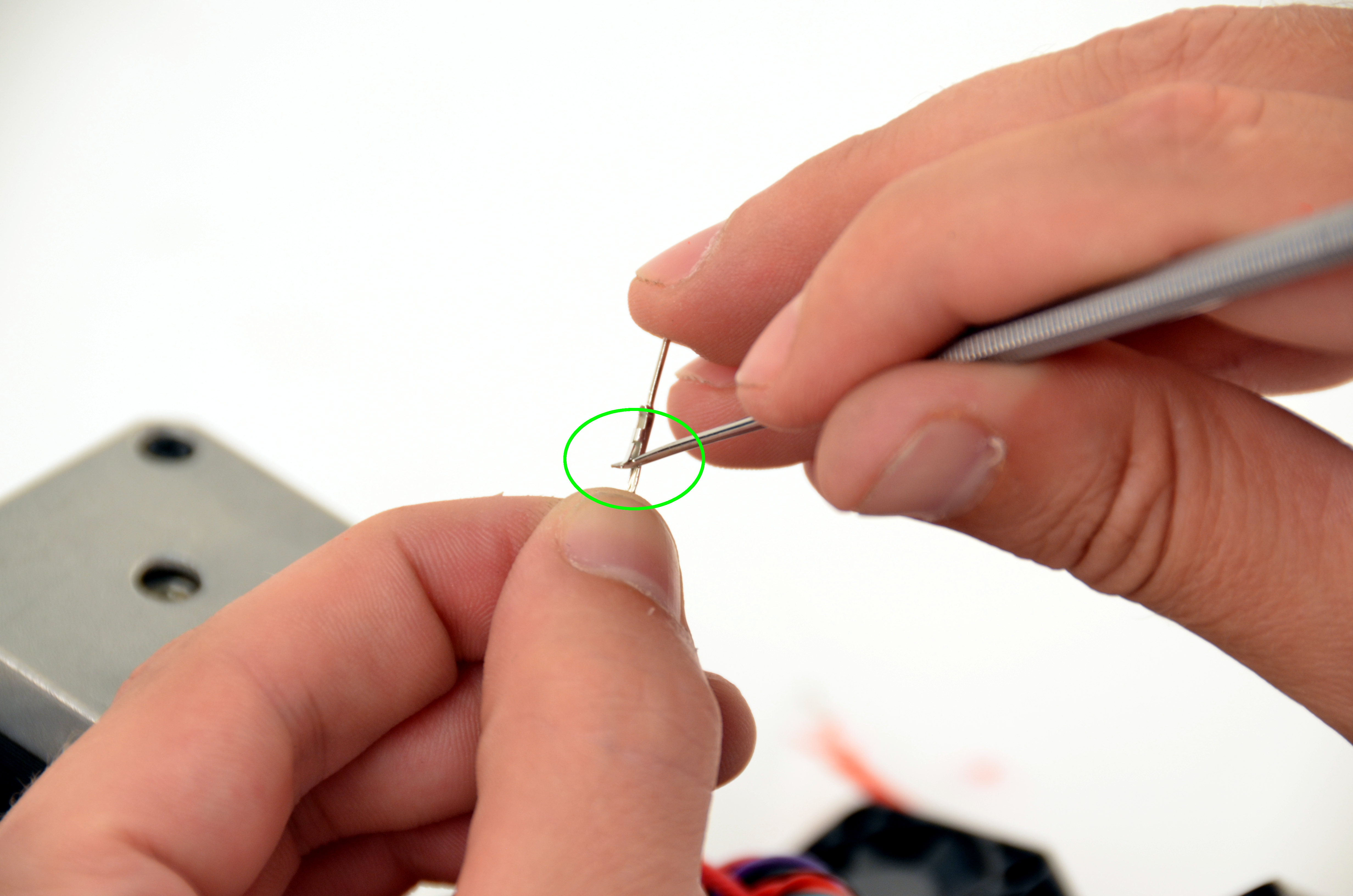
Insert the two heater cartridge wire pins into the connector.
Be sure the raised catch latches in the connector.
Reminder: Polarity does not matter.
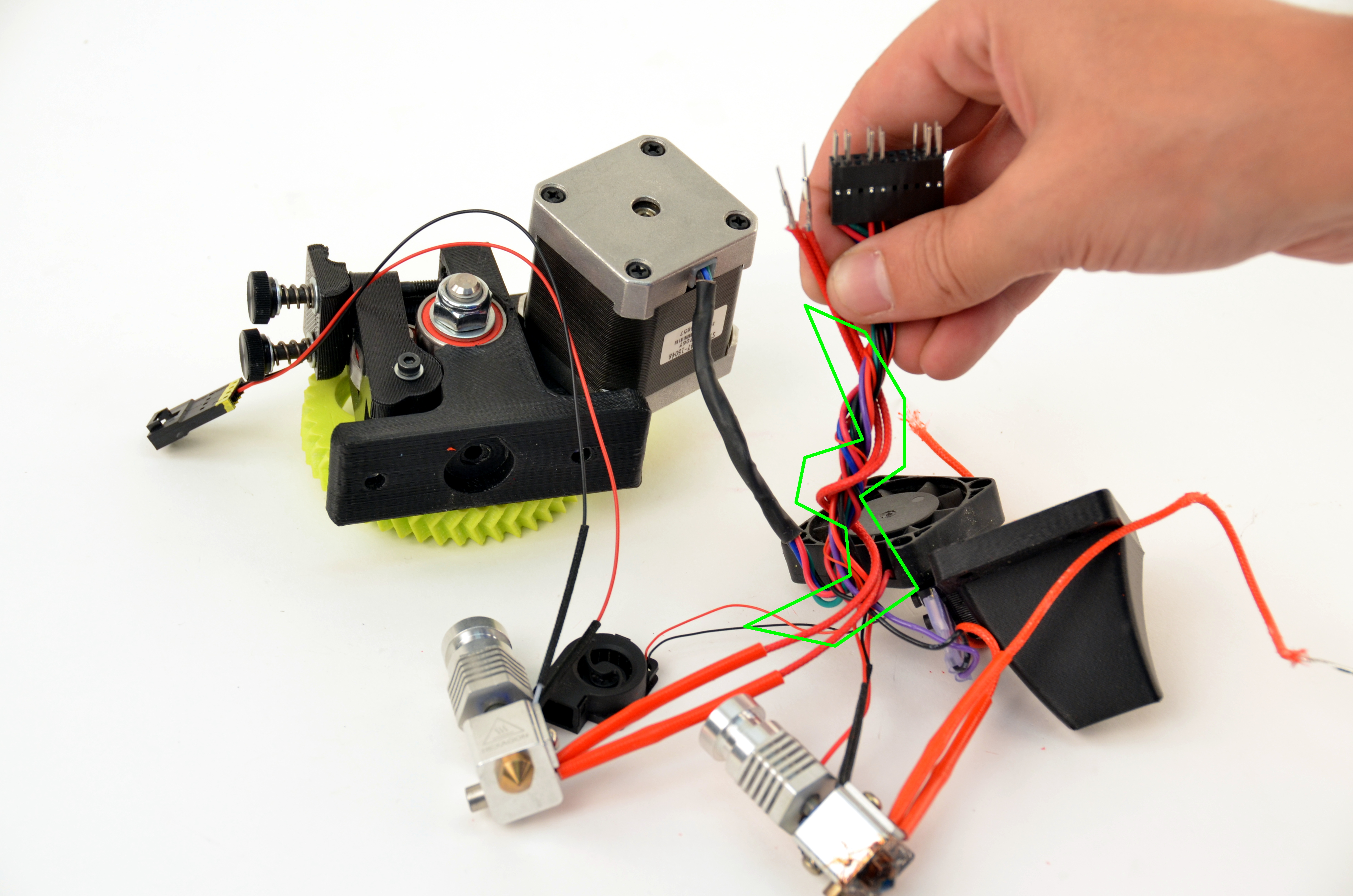
Using the dental pick included with your toolkit, gently push down on the catch that holds the pin in place. This will allow you to remove the existing pins.
Release and remove the two smaller wires.
The pick is sharp. Be careful.
Using your dental pick, gently raise the catches that were depressed in the previous step.
The pick is sharp. Be careful.
Using the dental pick included with your toolkit, gently push down on the catch that holds the pin in place. This will allow you to remove the existing pins.
Release and remove the two smaller wires.
The pick is sharp. Be careful.
The LulzBot Hexagon Hot End comes with standard length wires.
You will be required to wrap the two thermistor wires around the existing wiring harness twice to fit within the harness cover.
Insert the two thermistor wire pins into the connector.
Be sure the raised catch latches in the connector.
Reminder: Polarity does not matter.
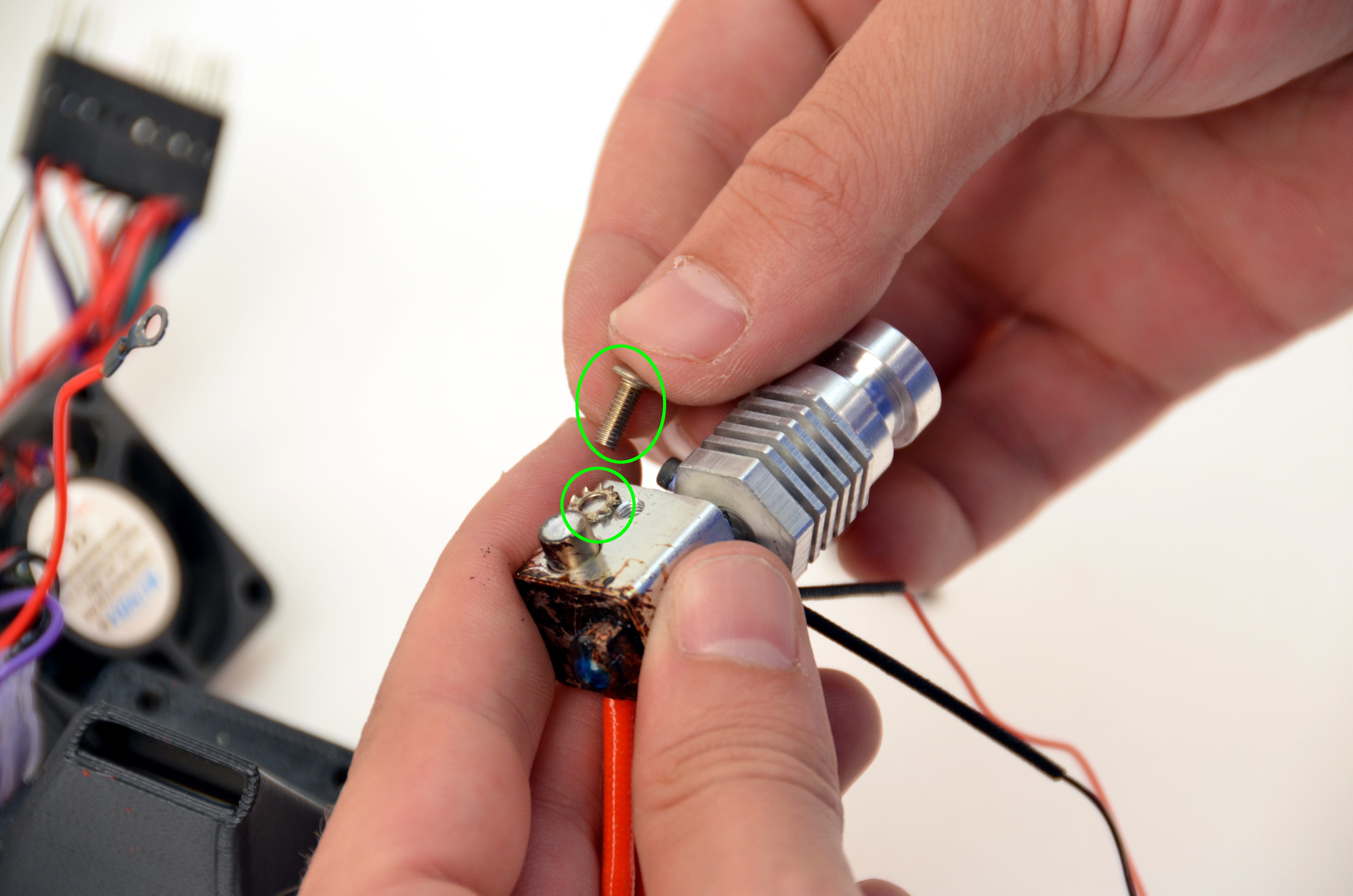
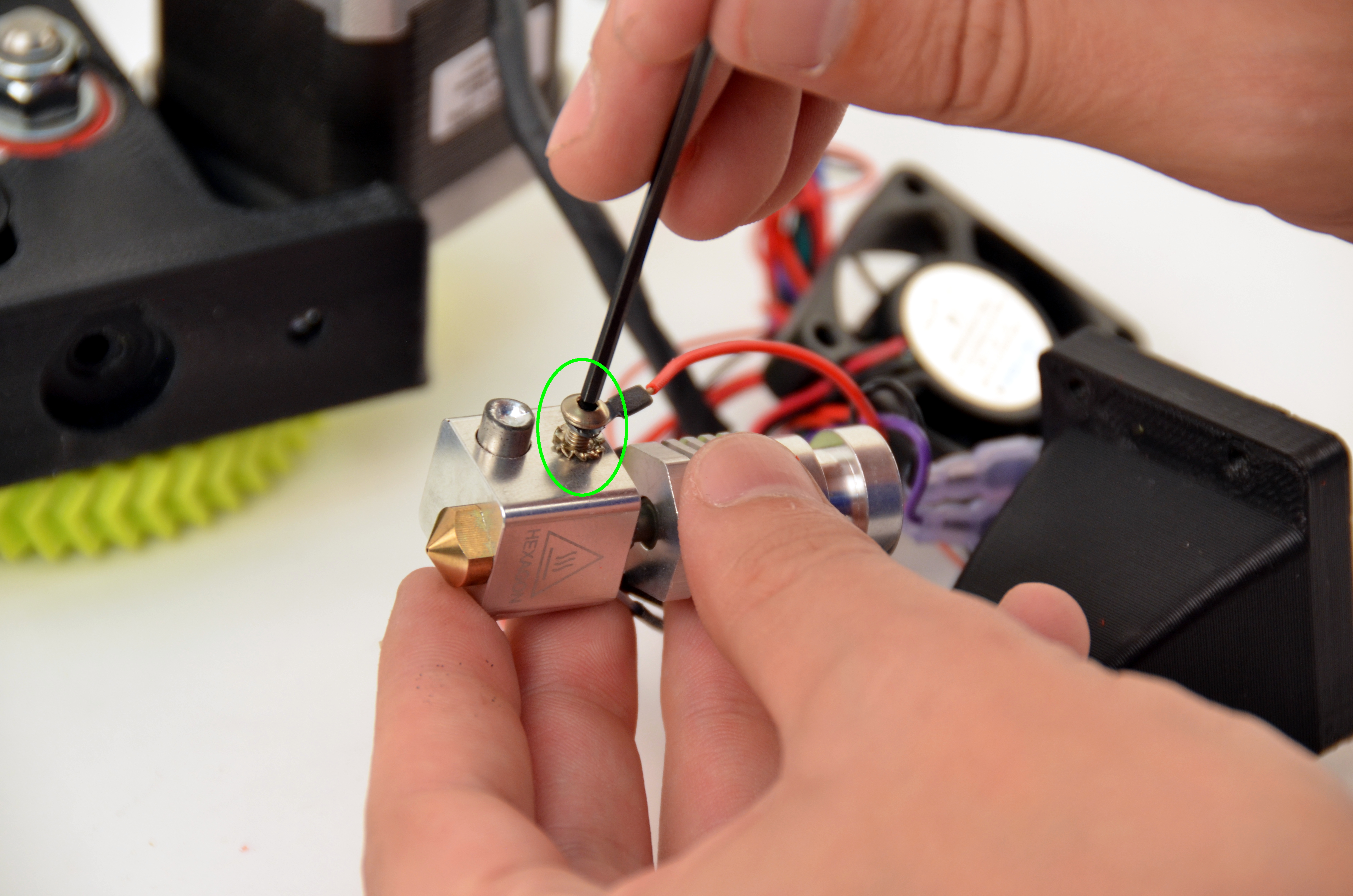
Unscrew the 5v leveling wire from the side of the hot end heater block using your 2mm driver.
Be sure to save the washer and screw.

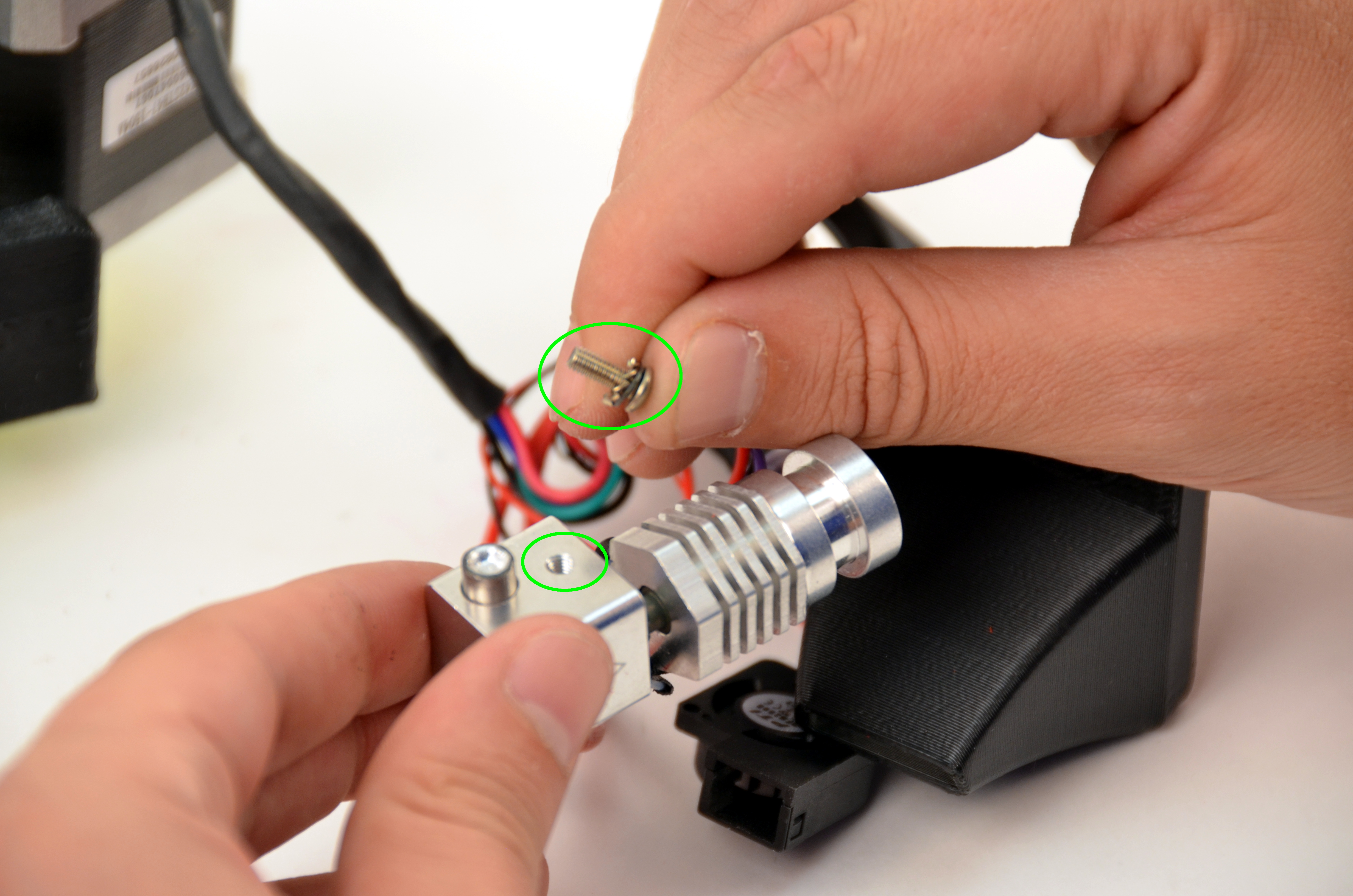
Install the 5v leveling wire and washer to the new hot end using your 2mm driver.
Route the wire behind the hot end, angled toward the hot end heat sinks.
Install the 3mm screws from the underside of the extruder body with the 2.5mm driver. Torque to 6 in*lbs.
Caution: the extruder body can crack if there is too much torque applied to the mounting screws. Do not apply more than 6 in*lbs to the 2 M3x15mm screws.
Ensure that the Hexagon text is facing forward, with the thick red wires coming out of the right hand side of the block.

Route all wires towards the back of the tool head to allow room for the extruder fan mount.
Keep the micro blower wires towards the front.
Using your your 2mm driver, install the extruder fan mount to the side of the extruder.
Make sure that the wires are routed to the back.
Use your 2.5mm driver and two M3 screws, secure the fan to the fan mount.
Use your 1.5mm driver to install the micro blower back onto the tool head.
Replace the cable housing around the wiring harness and secure it using a zip tie.
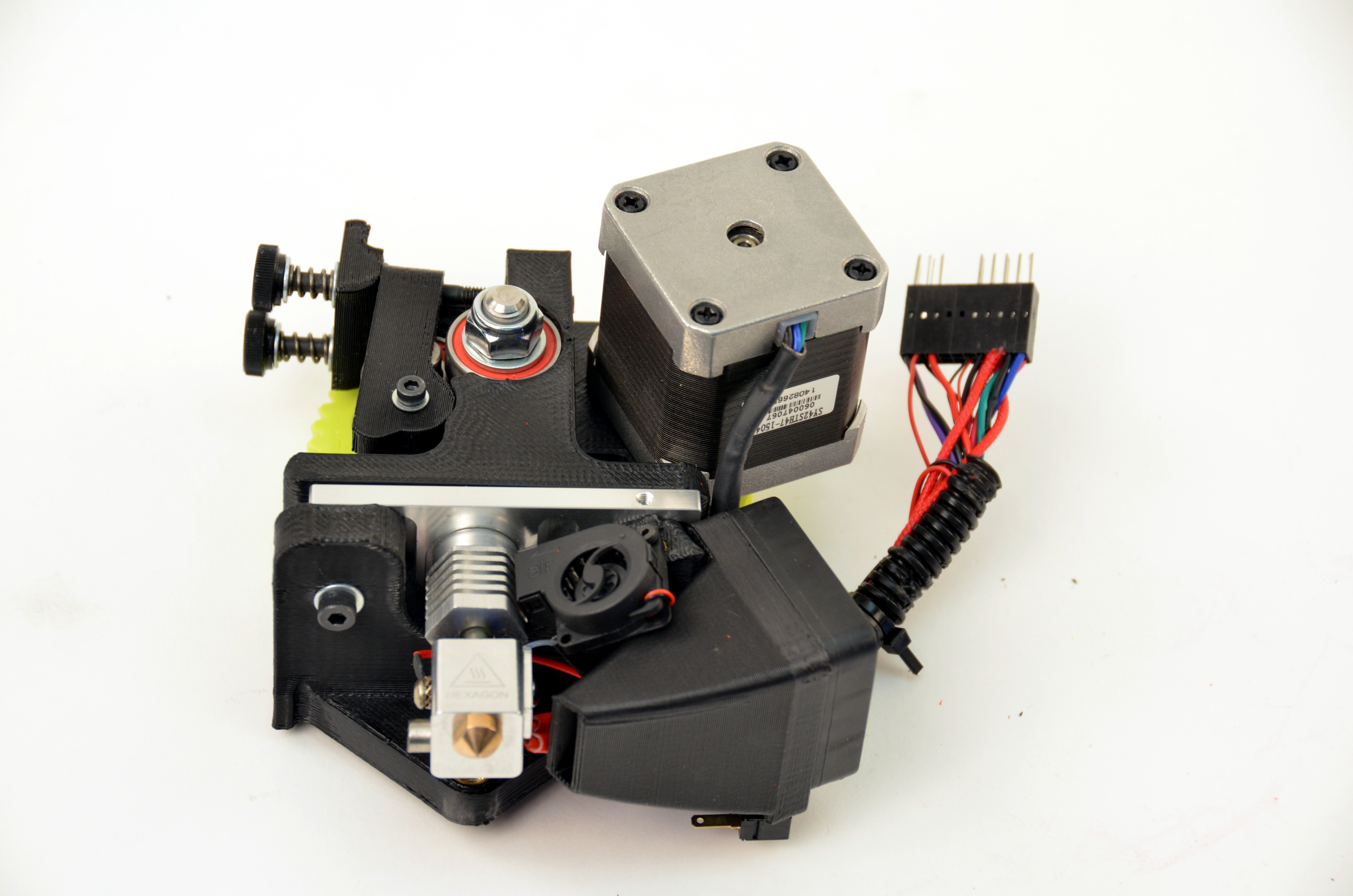
Your tool head should match the image.
Press the repaired toolhead onto the X axis carriage, aligning the tab with the cutout on the back of the new tool head.
Secure it to the X axis carriage by loosely screwing in the top two screws. Leave the top two screws loose.
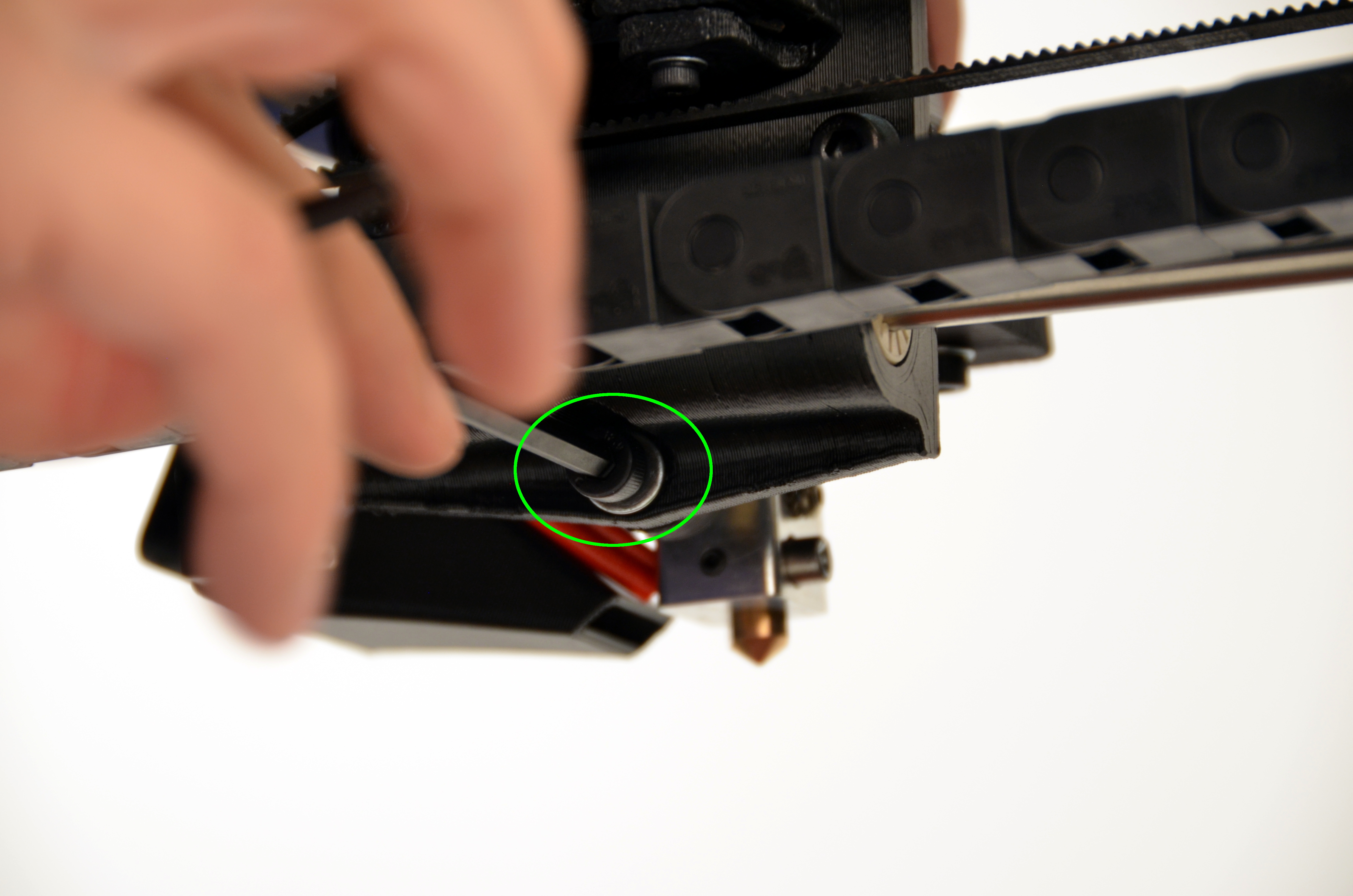
Install the last screw into the bottom of the X axis carriage and fully tighten.
Tighten the top two screws.
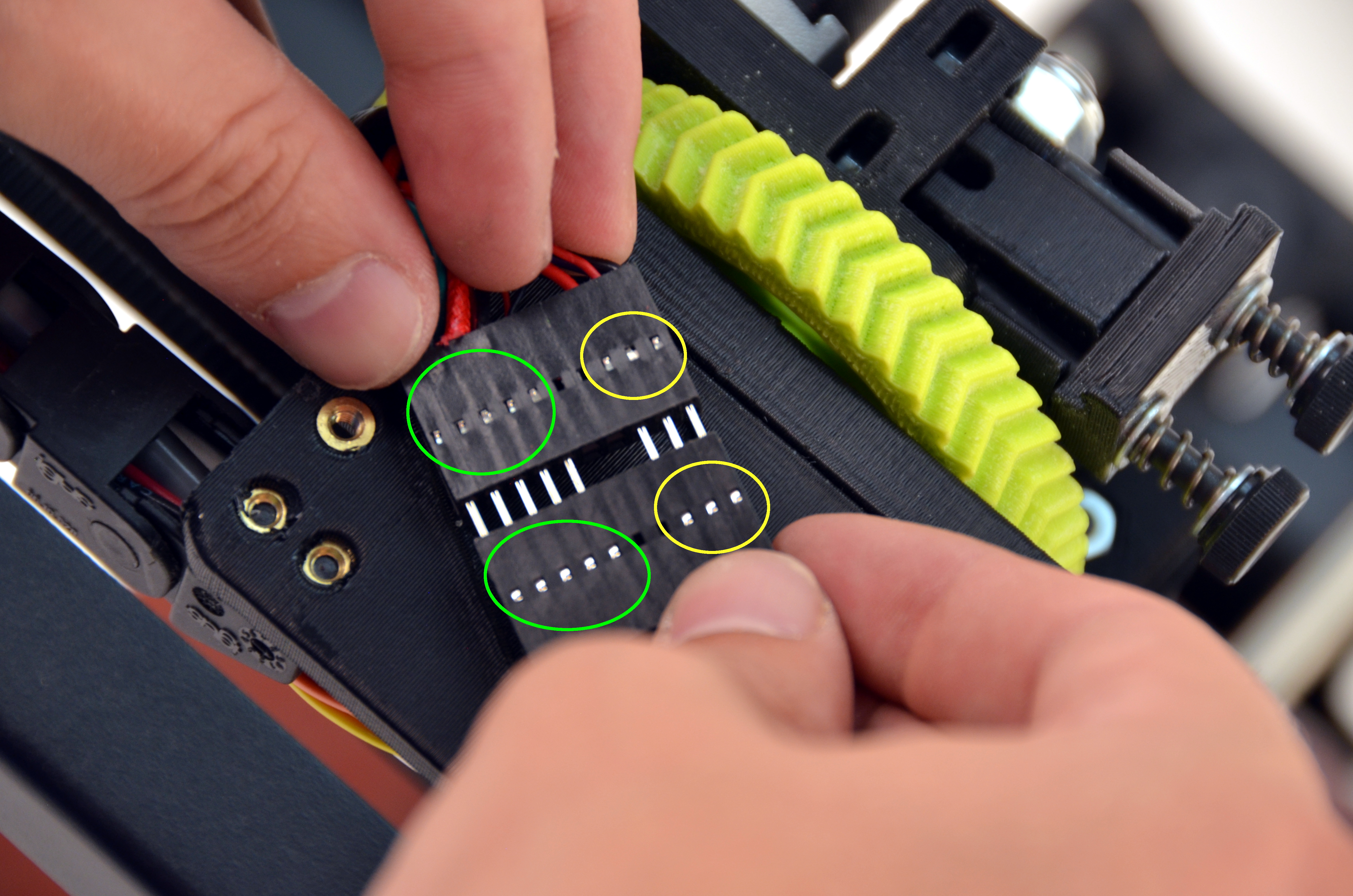
Plug in the two 16 pin connectors, making sure to match them based on the pins in the connector.
Verify the connectors are appropriately aligned before proceeding
Cover the connector with the cover and attach it to the X axis carriage using two M3 screws and the 2.5 mm driver.
Ensure the wires are routed through the gap in the cover.
Verify everything is working properly:
Does your micro blower turn on when your 3D printer is powered on?
Do you get any errors when connecting through Cura?
Print your favorite test object to verify functionality.
Be sure to watch the bed probing sequence, to ensure everything is hooked up properly.
Questions? Contact Technical Support by emailing Support@LulzBot.com, or by calling 1-970-377-1111.