Open HardwareAssembly Instructions
Guides for installation and assembly of the LulzBot line of products made by FAME 3D LLC.
Guides for installation and assembly of the LulzBot line of products made by FAME 3D LLC.
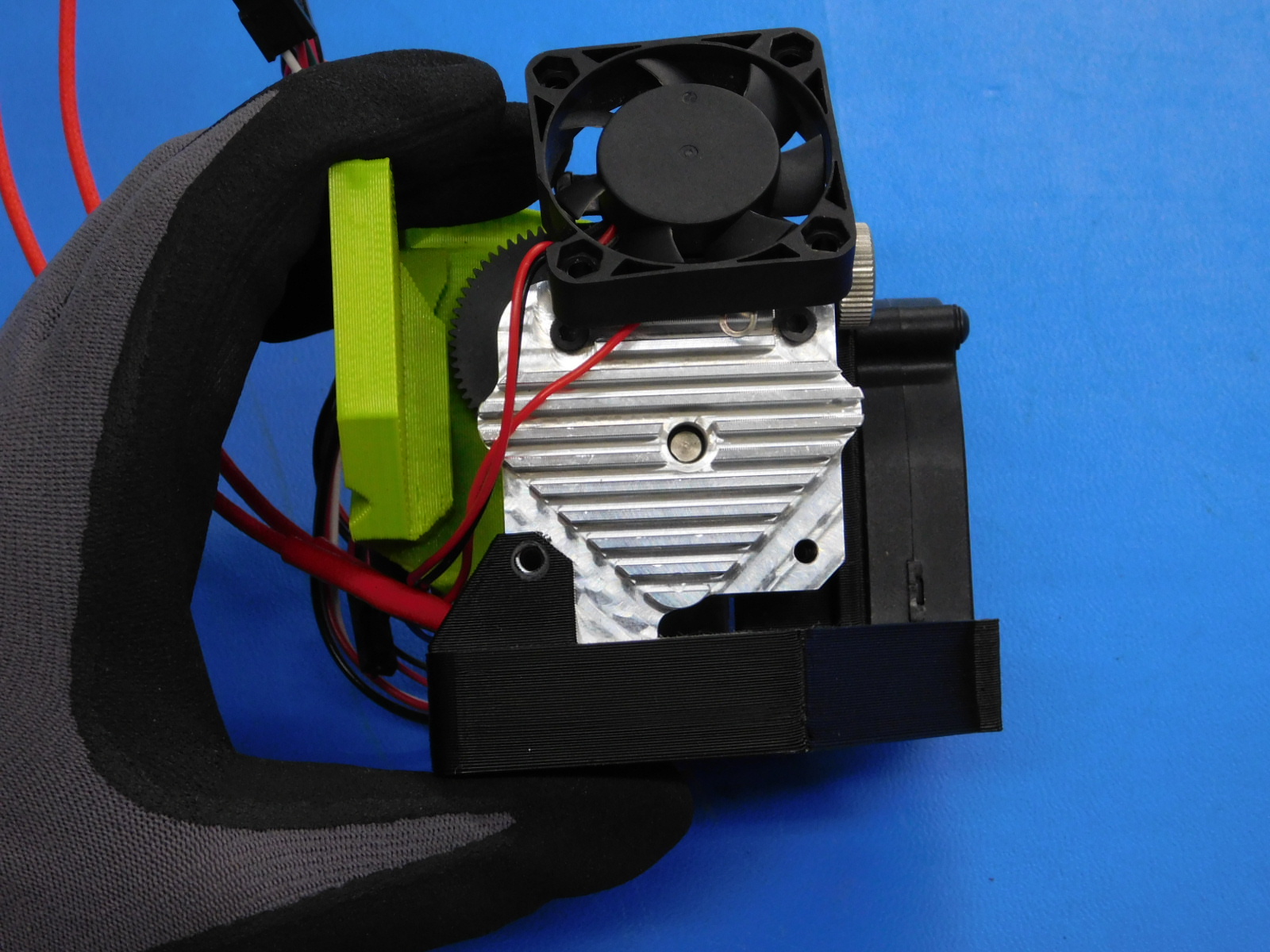
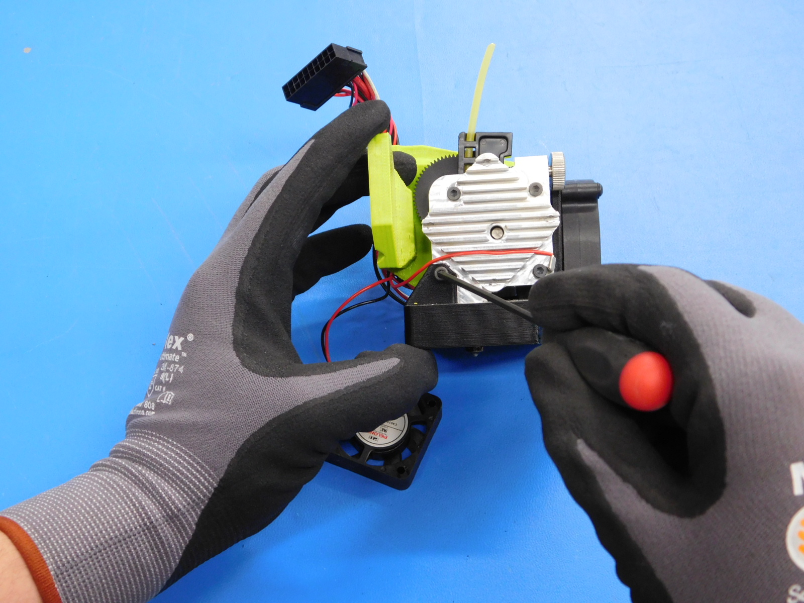
Using the 2.5mm hex key, loosen and remove the four M3 screws that hold the fan onto the heatsink.
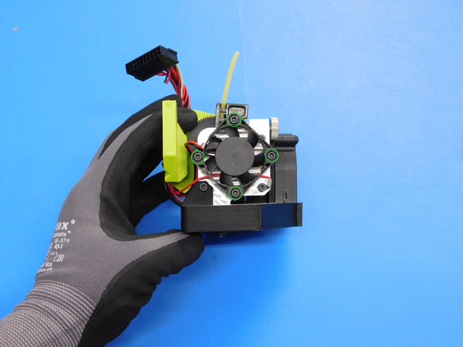


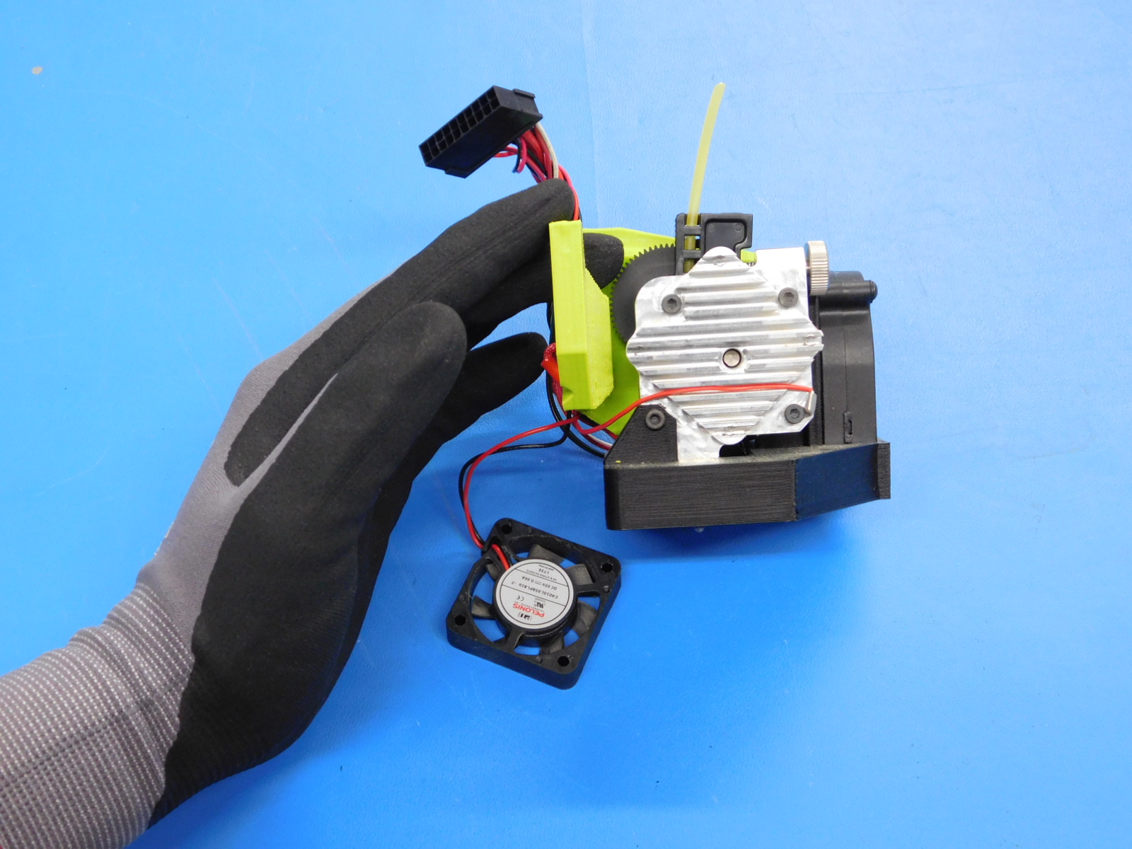
Loosen and remove the four heatsink mounting screws and remove the fan duct by sliding down off the bottom of the toolhead.

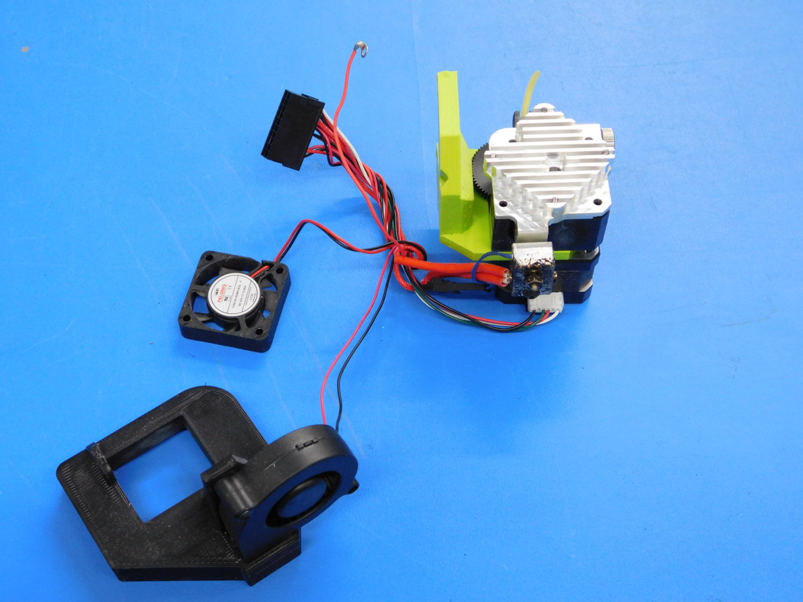
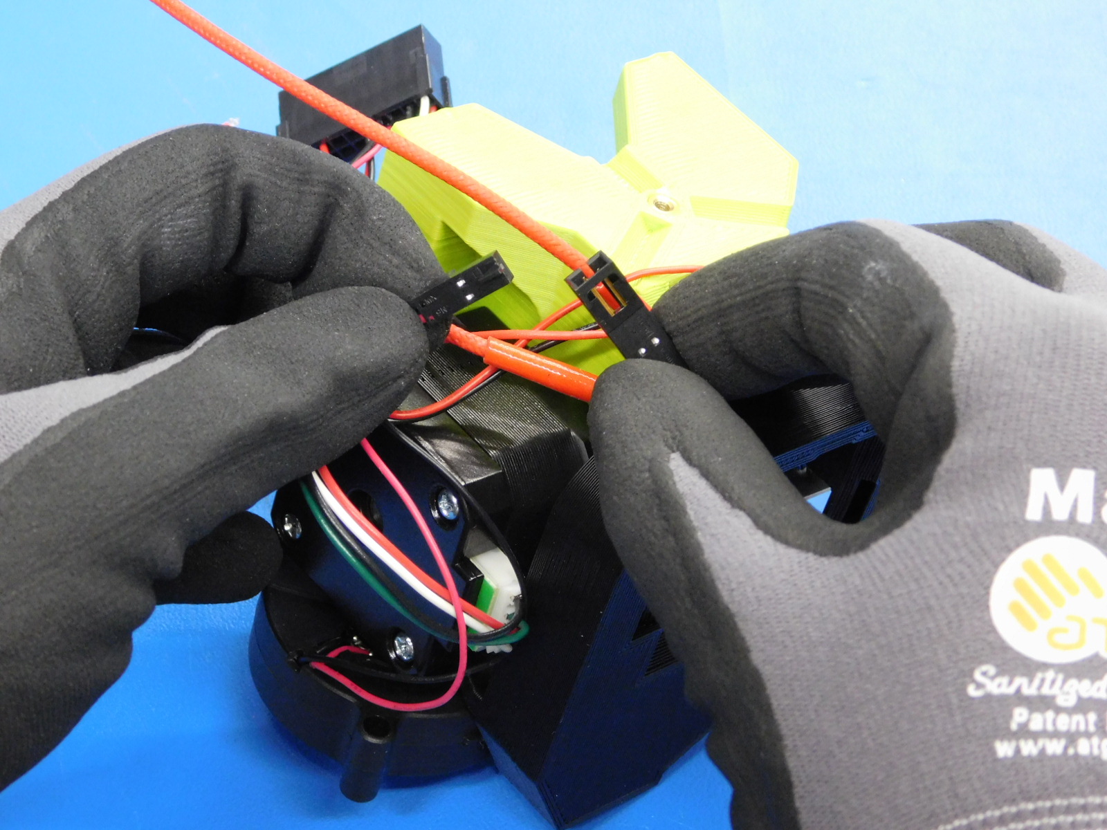
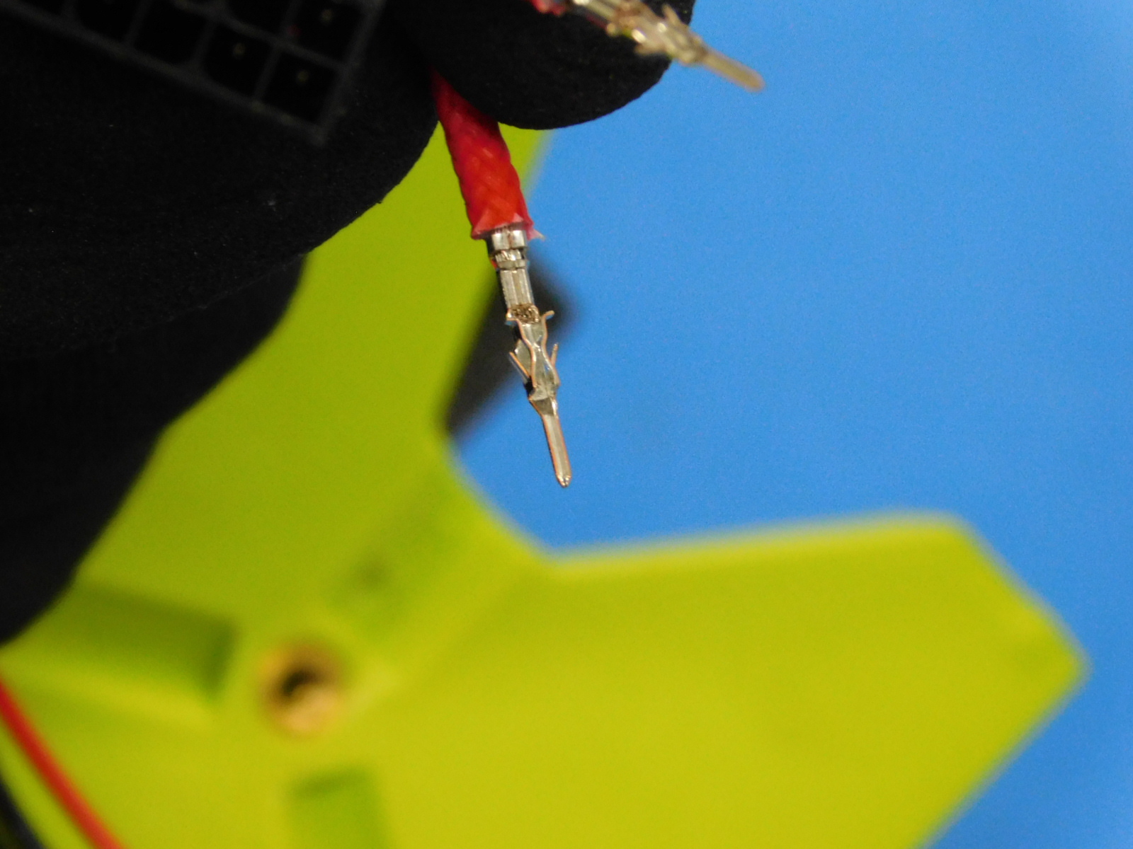
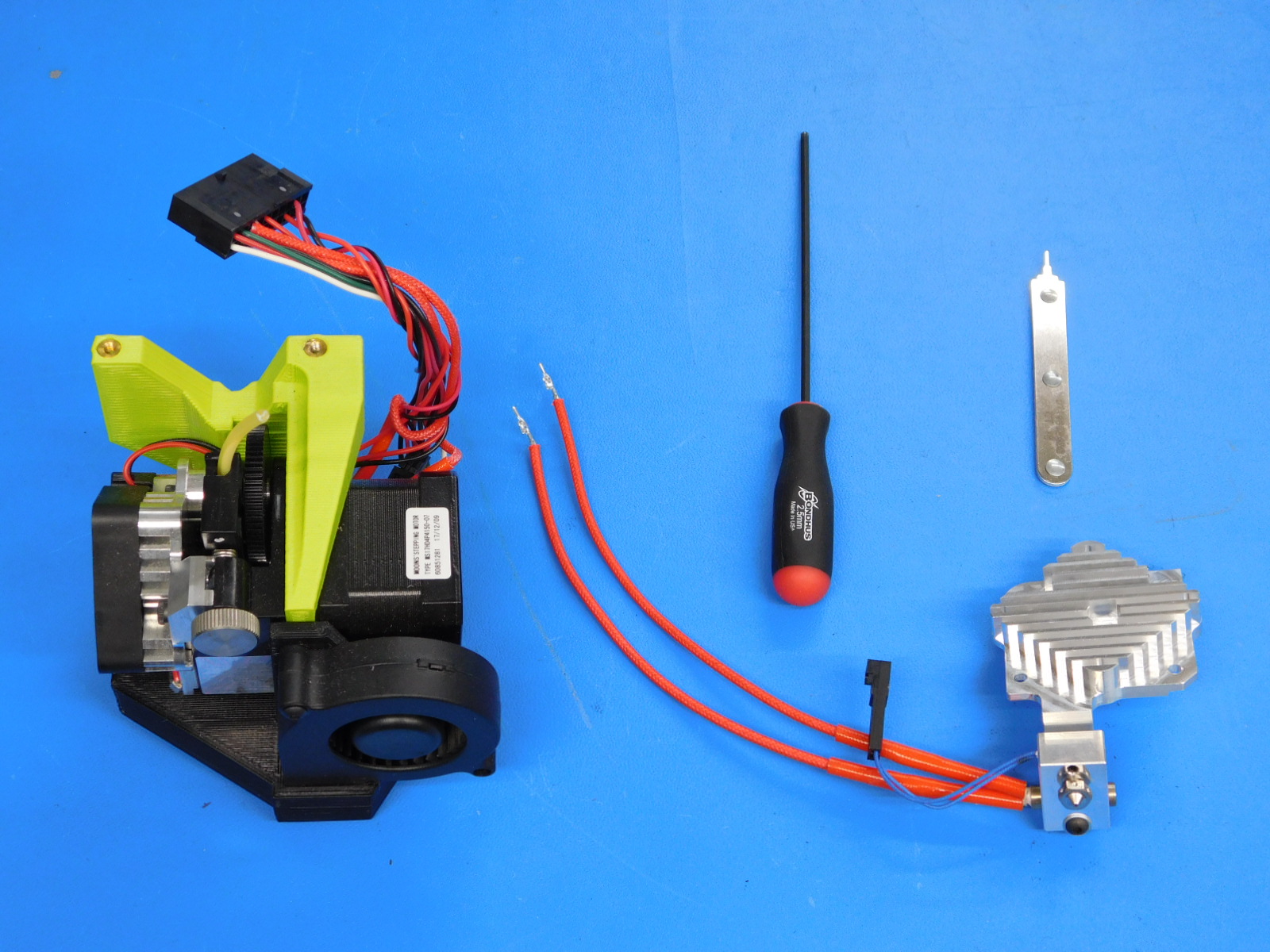
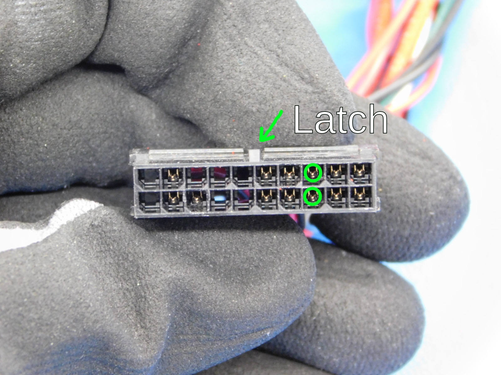
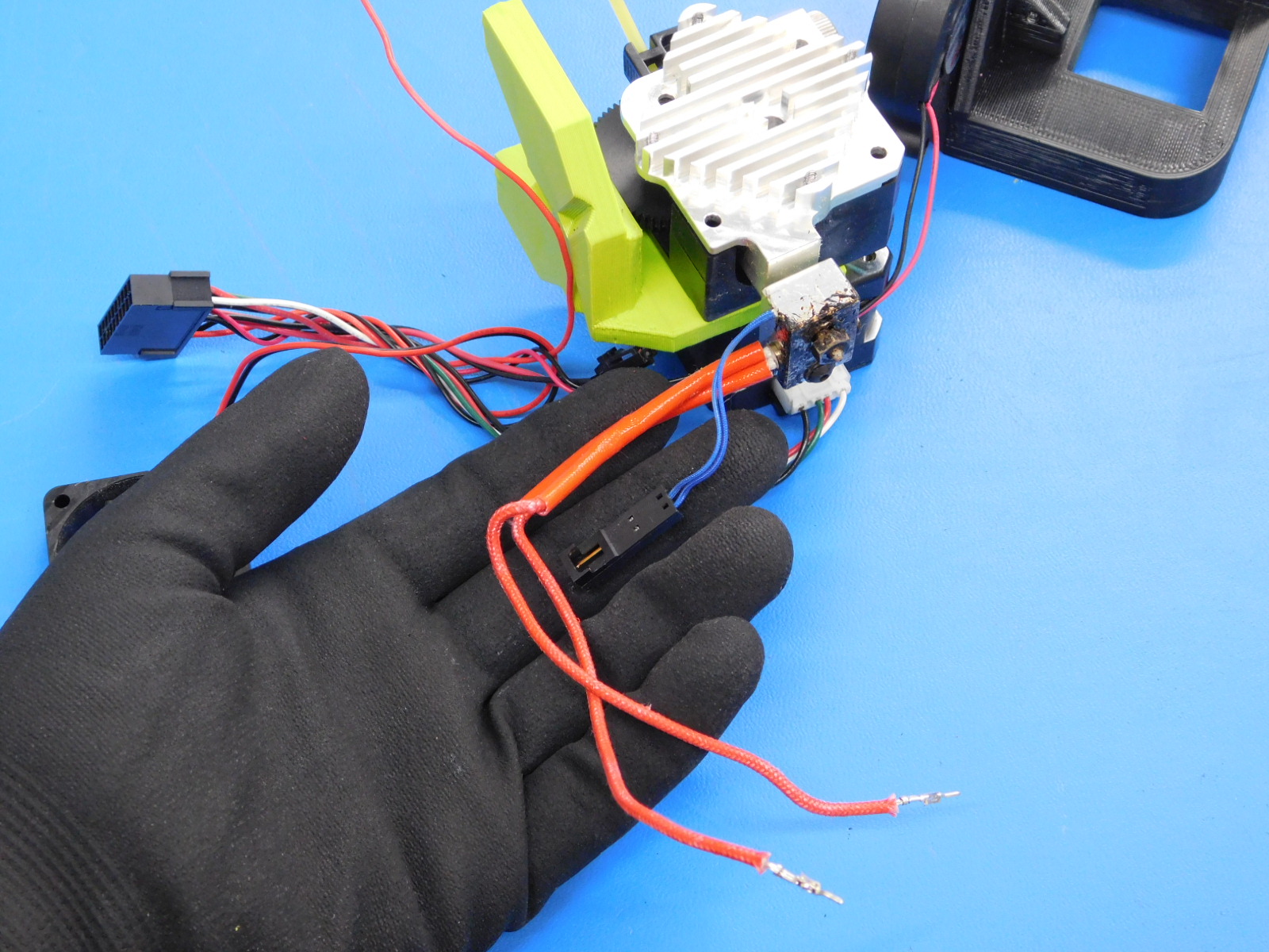
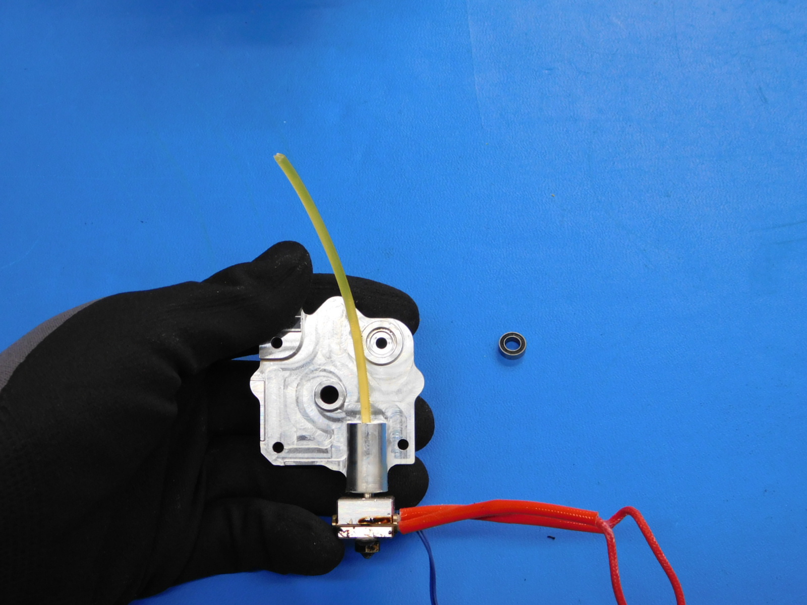
Using the pin removal tool, carefully remove the pins for the heater.
Note: this step is only required if the hot end assembly needs to be replaced.
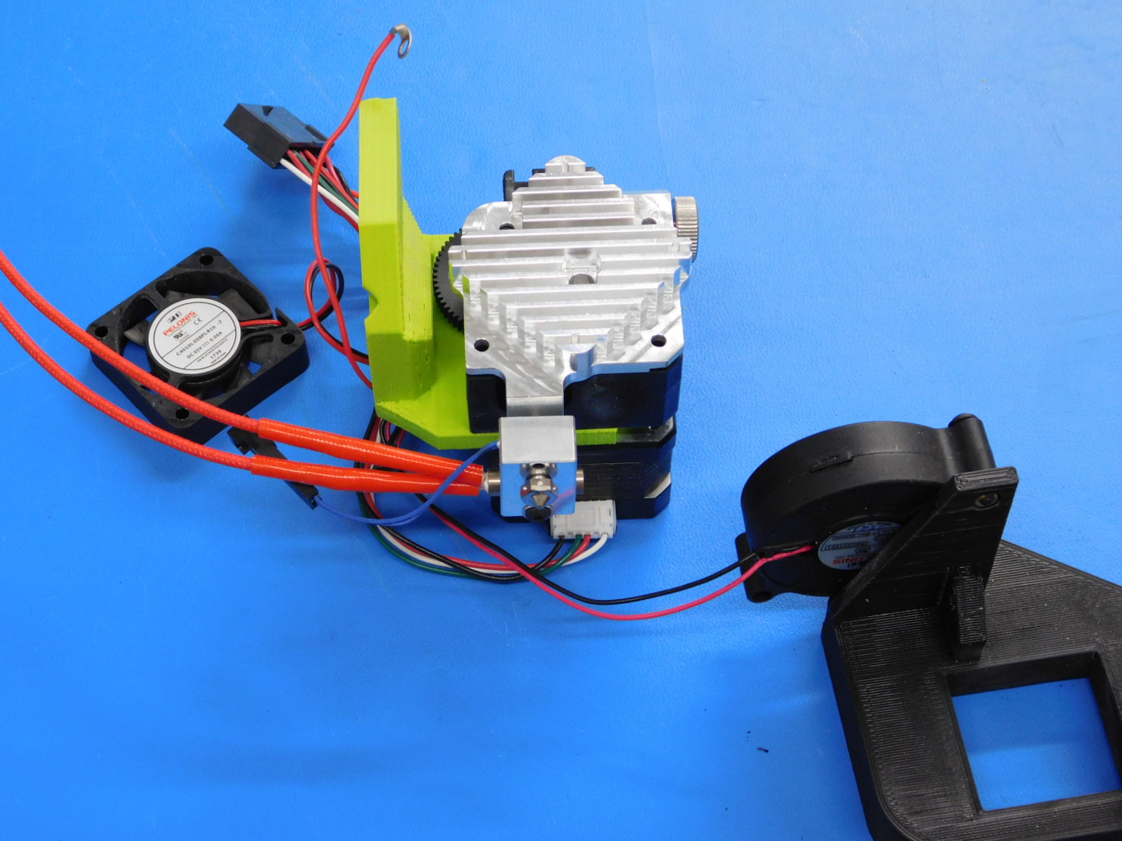
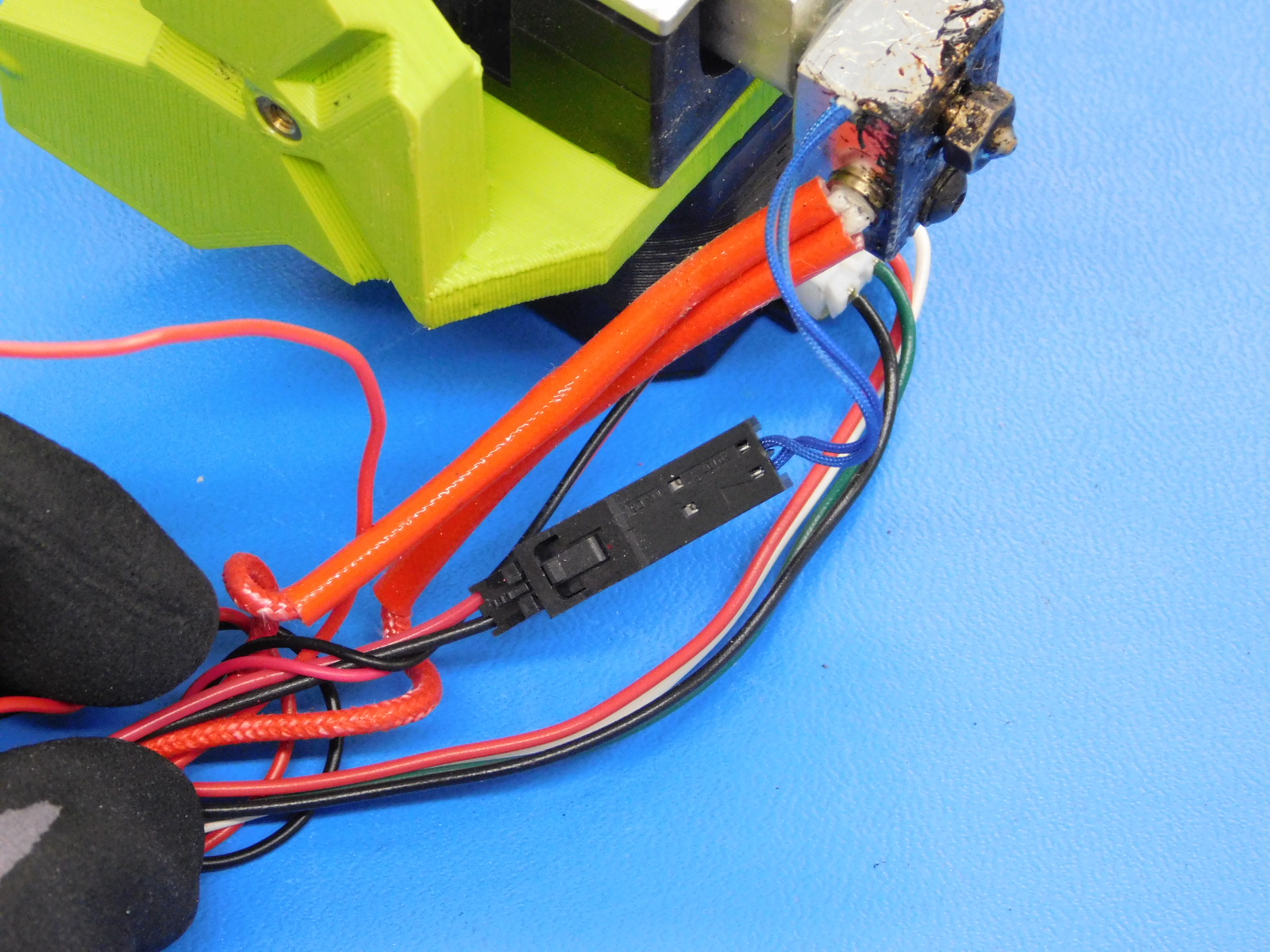
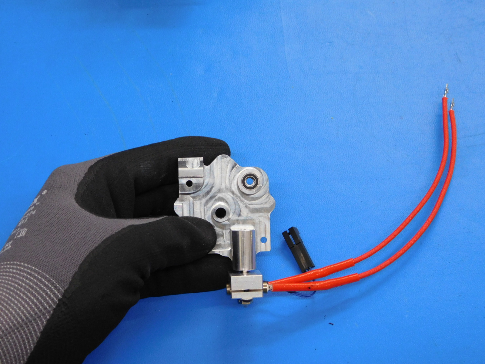
Depress the retention tab on the connector housing and disconnect the thermistor extension. At this point, the hot end assembly can be lifted and removed.
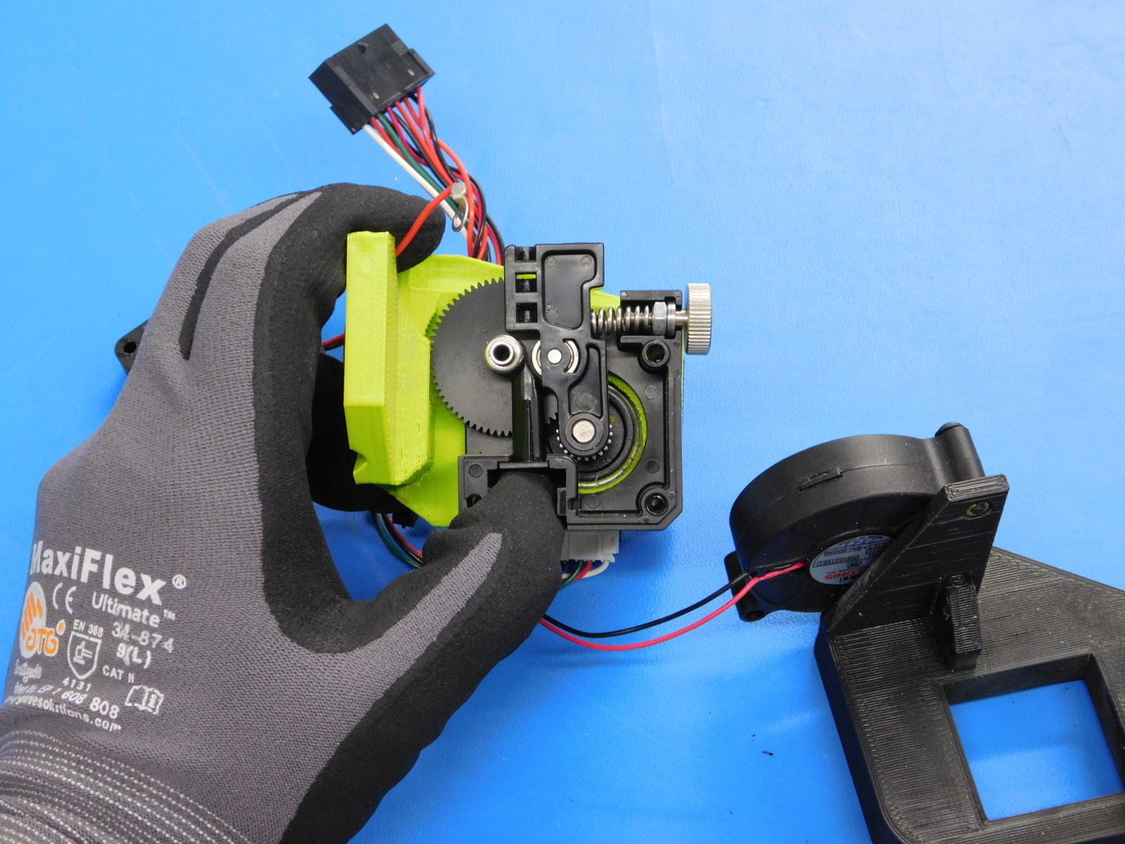
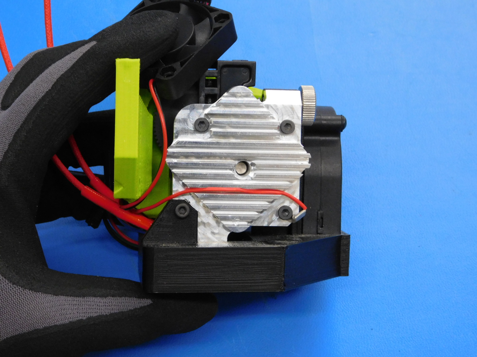
Remove the heatsink assembly. Loosening the idler compression screw can help. Turn clockwise to decompress the spring.
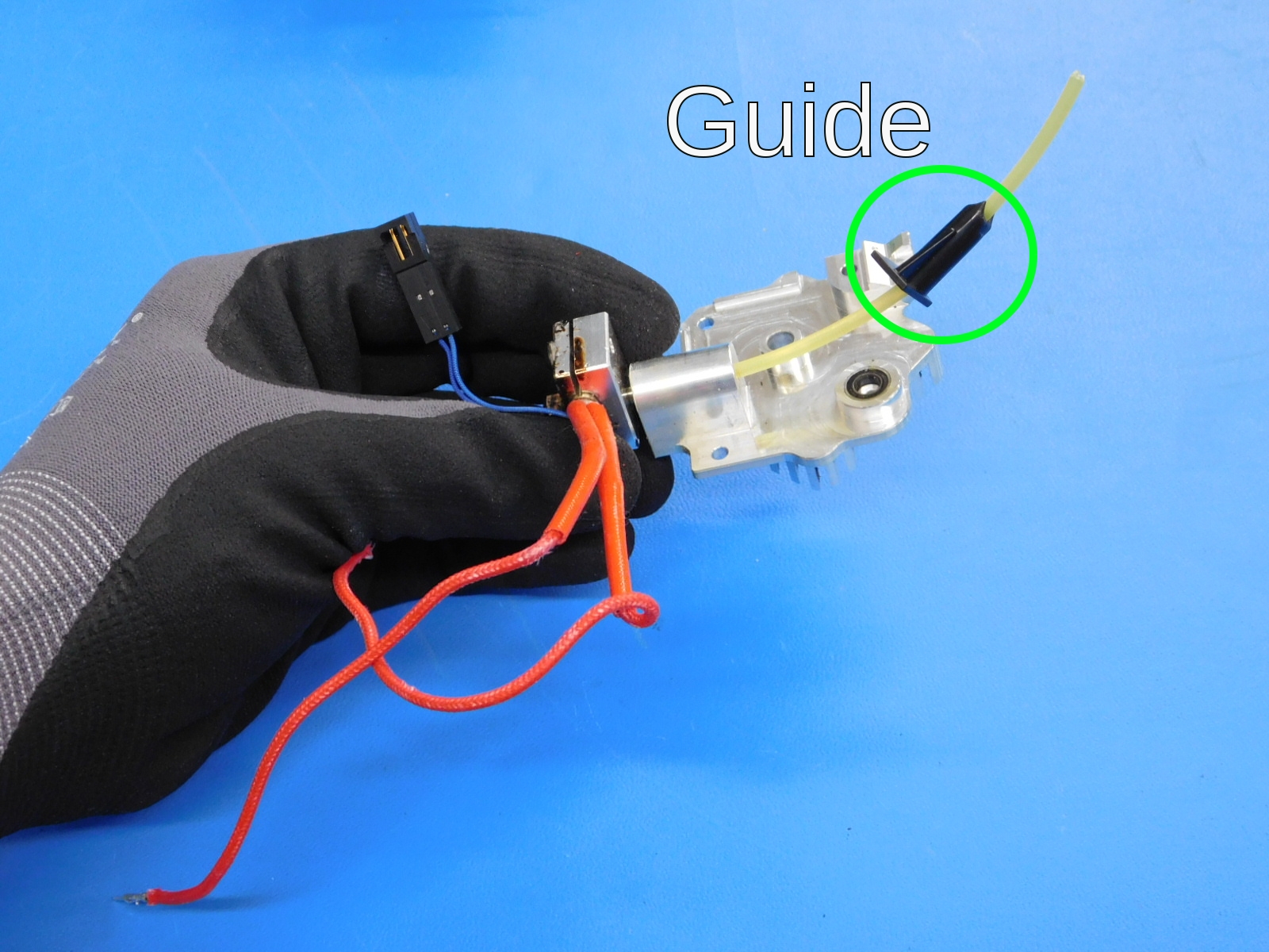
Inspect the bearings, hobbed shaft, idler arm, guide tube, and drive gears. Clean and replace parts as necessary.
Specifically, look for plastic or worn teeth on the hobb, cracks or wear on the idler or guide, or excessive wear or missing teeth on the drive gears.
Remove the bearing from the old heatsink and install it in the new heatsink. A spare stepper motor shaft is a good tool to remove the bearing. Just push the shaft into the bearing and then wiggle and pull the bearing out.
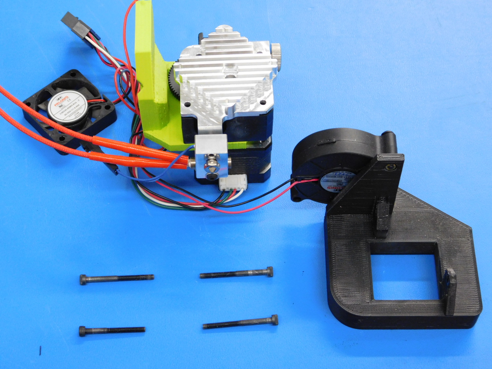
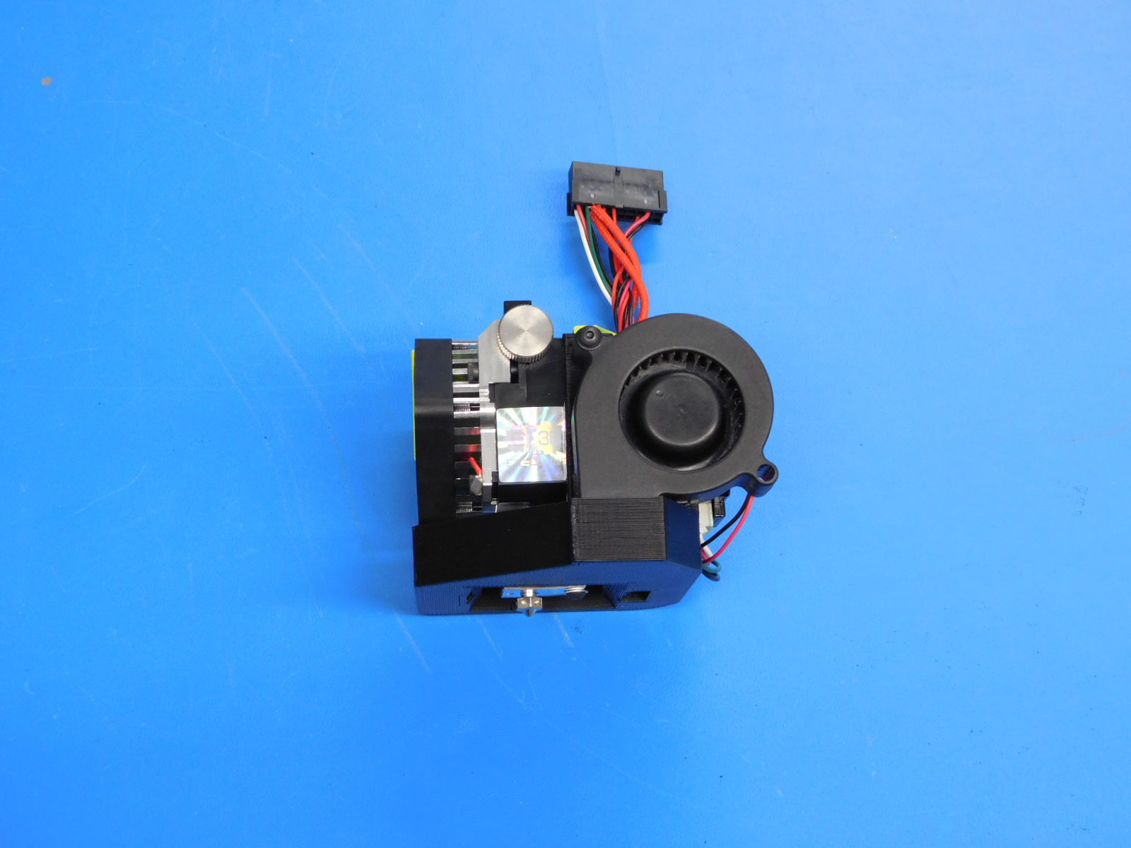
Reassemble the toolhead as shown observing the following:
Take care to not pinch any wires when installing the new heatsink assemlby.
The fan duct must be installed before the two bottom M3 screws can be installed.
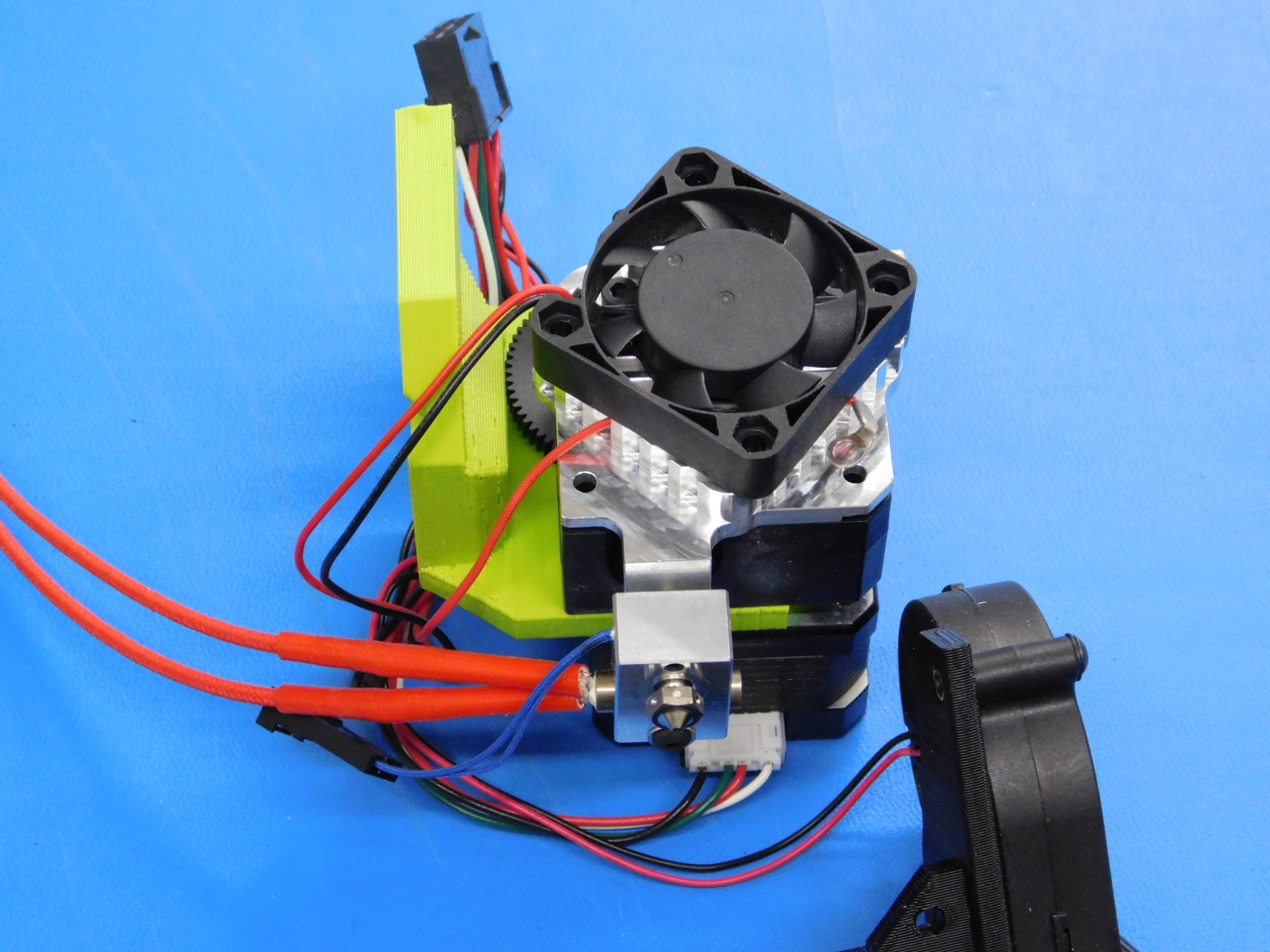
The red ground wire goes thought the heatsink fins and on the bottom right M3 screw.
The fan must be up on the heatsink before the fan duct is installed so that the wires are routed correctly.
The short M3 screw goes in the bottom left hole.
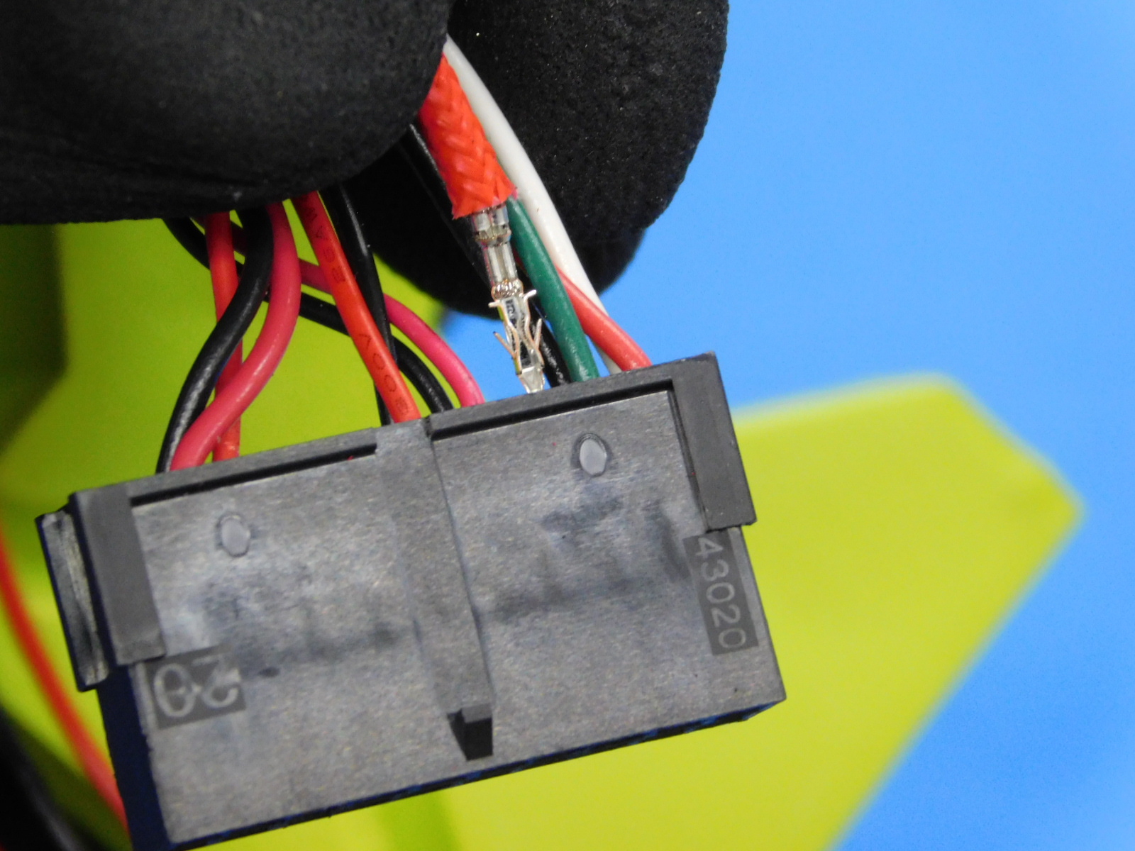
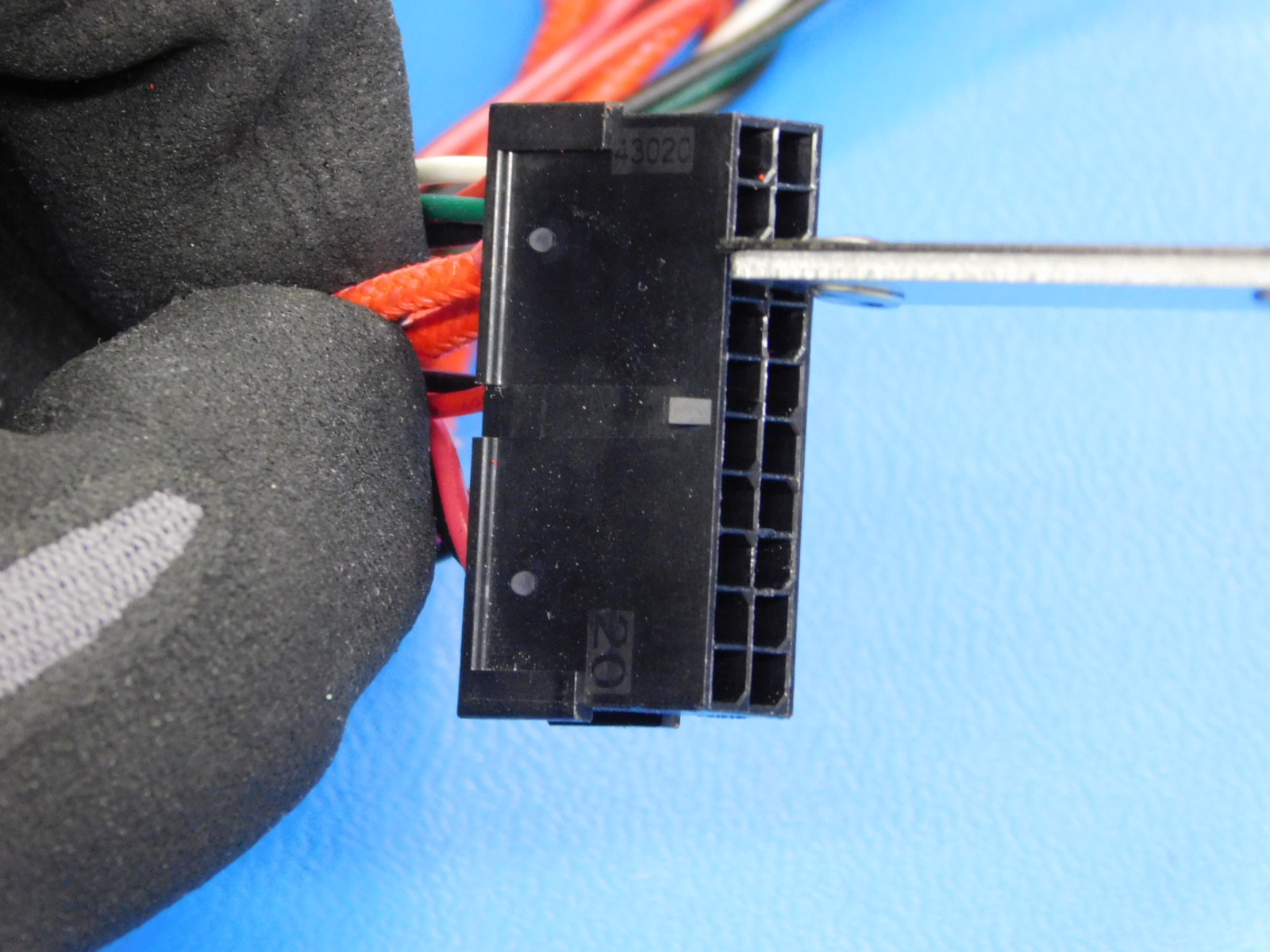
Both heater connectors go with the top of the U shaped crimp facing the triangular latch of the connector.
The heater and thermistor wire pairs are not polarized; the order of the wires can be switched without affecting function.
For more details, see the Assembly OHAI