Open HardwareAssembly Instructions
Guides for installation and assembly of the LulzBot line of products made by FAME 3D LLC.
Guides for installation and assembly of the LulzBot line of products made by FAME 3D LLC.
Components Required:
1x- Frame Assembly (AS-PR0064)
1x- Z Axis left assembly (AS-PR0042)
1x- Z Axis right assembly (AS-PR0048)
1x- X Carriage assembly (AS-PR0055)
1x- Extruder assembly (AS-TH0022)
3x- M5x14 SHCS (HD-BT0049)
1x- X carriage cap (PP-GP0280)
2x- 8mm Smooth Rod, 315mm (HD-RD0035)
2x- M3 x 12 mm Socket Head Cap Screw black oxide(HD-BT0039)
28x- M3 x 6 mm Flat-Head Socket Cap Screw black oxide(HD-BT0128)
2x- M3 Set screw (HD-BT0012)
3x- M5 Washer black oxide(HD-WA0040)
2x- M3 washer black oxide(HD-WA0038)
Tools Required-
Cutters
Needle nose pliers
Phillips screwdriver
508C Sonic Tension Meter
2.5 mm hex driver
2.0 mm hex driver
1.5 mm hex driver
2in*lbs torque driver
5in*lbs torque driver
Place the Z Axis left assembly into the frame assembly
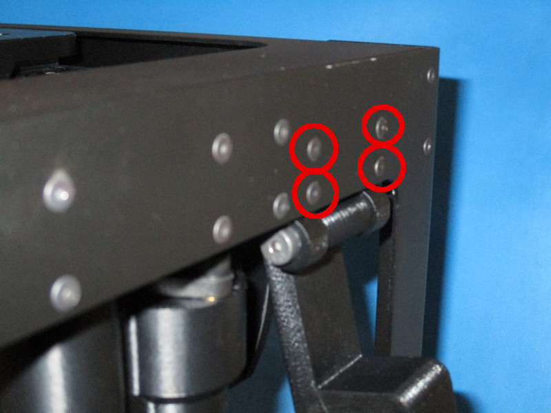
Secure the Z Lower left of the Z Axis left assembly to the frame assembly with four M3 x 6 mm flat-head socket cap screws using a 2.0 mm hex driver, torque to 5 in*lbs
Secure the Z Upper Left of the Z Axis left assembly to the frame assembly with six M3 x 6 mm flat-head socket cap screws using a 2.0 mm hex driver, torque to 5 in*lbs
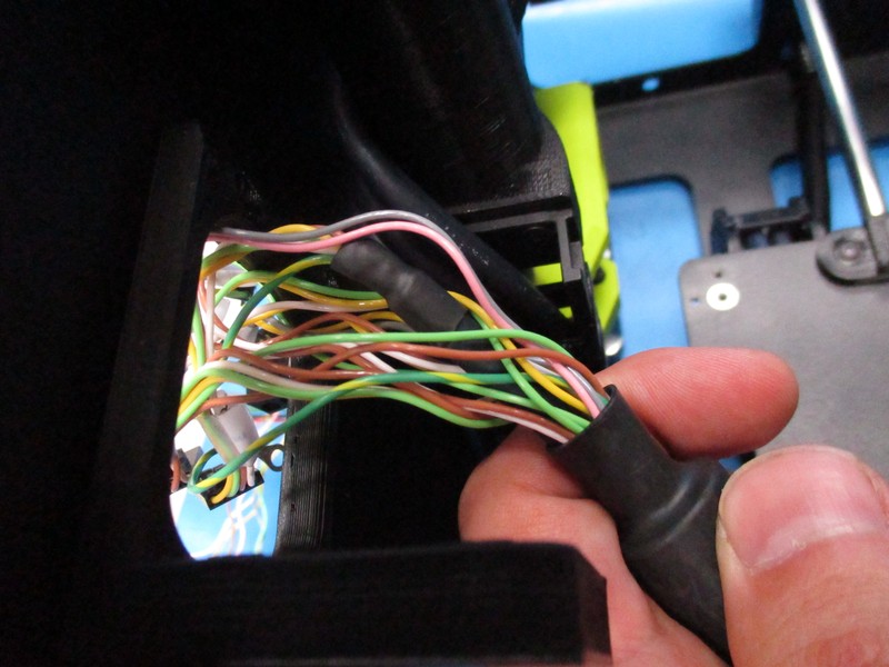
Run the five gray cables through the Upper Strain Relief
Attach the X/Extruder Cable harness to the Upper Strain Relief with two M3 x 6 flat-head socket cap screw using a 2.0 mm hex driver, torque to 5 in*lbs


Place the Z Axis right assembly into the frame assembly
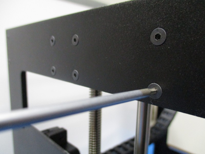
Secure the Z Lower right of the Z Axis right assembly to the frame assembly with four M3 x 6 mm flat-head socket cap screws using a 2.0 mm hex driver, torque to 5 in*lbs
Secure the Z Upper right of the Z Axis right assembly to the frame assembly with six M3 x 6 mm flat-head socket cap screws using a 2.0 mm hex driver, torque to 5 in*lbs

Flip the frame assembly upside down
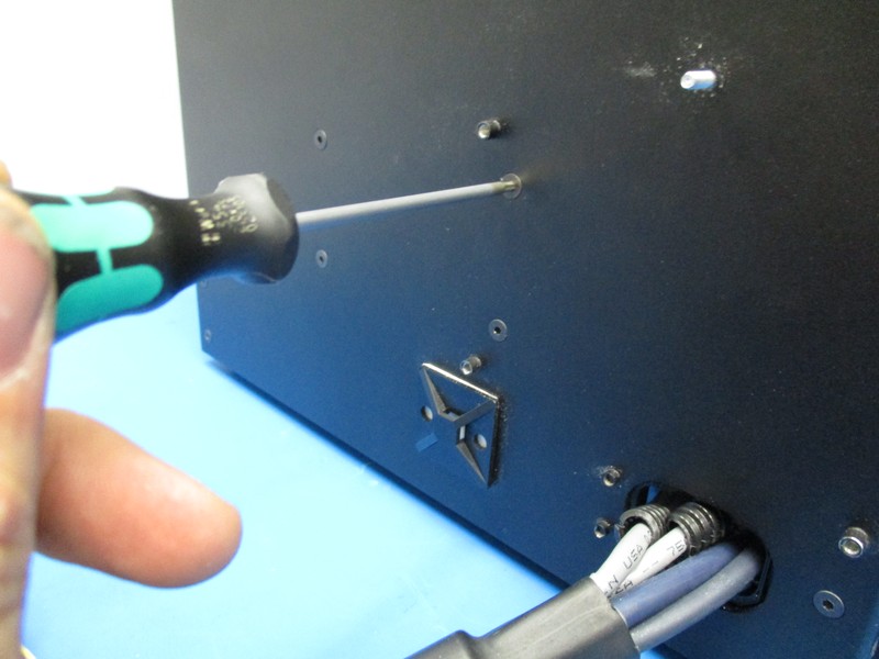
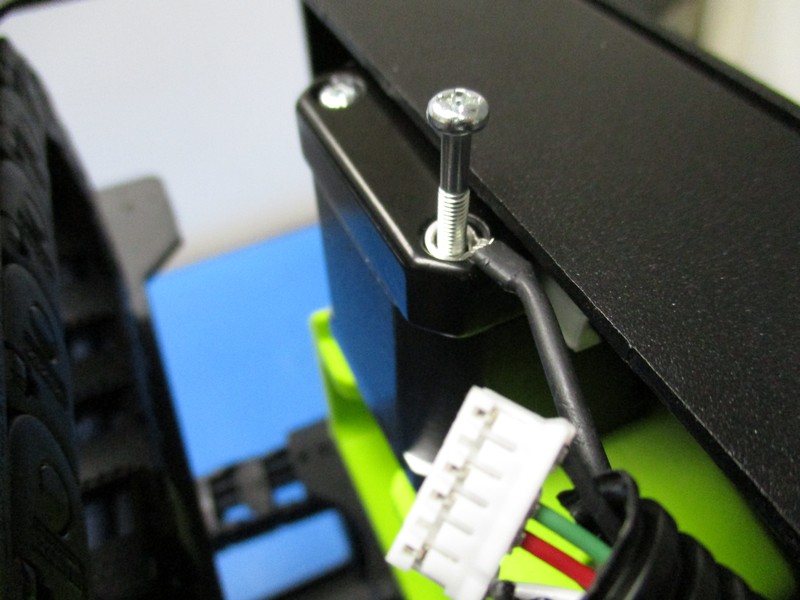
Completely remove one of the Z right motor housing screws using a Phillips screwdriver
Insert the right motor's housing screw through the ring terminal of the Z motor right motor cable, reinstall the housing screw into the Z right motor capturing the ring terminal
Completely remove the one Z left motor housing screws
Insert the left motor's housing screw through the ring terminal of the Z motor left motor cable, reinstall the housing screw into the Z left motor capturing the ring terminal
Flip the frame assembly right side up
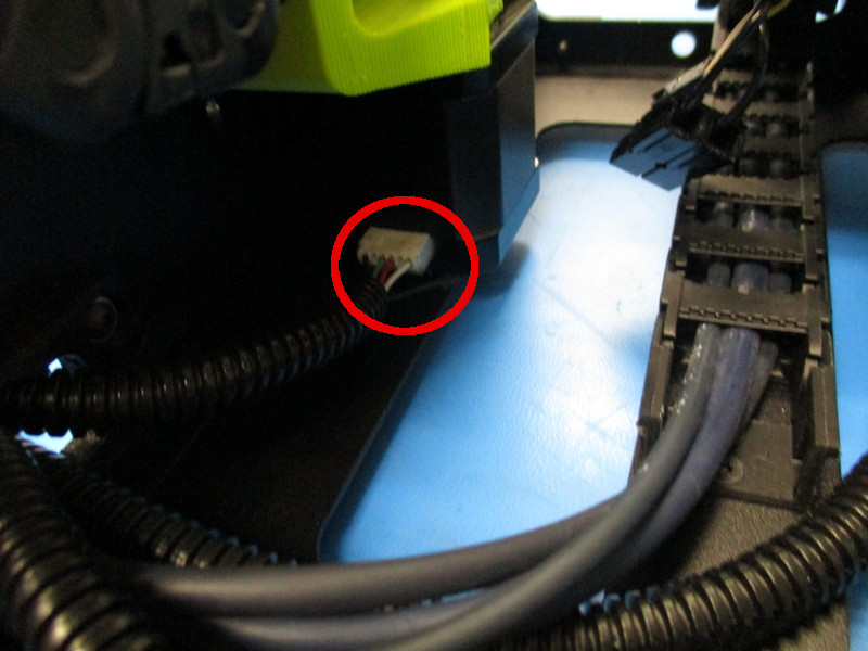
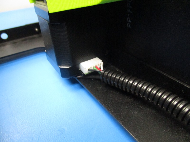
Connect the Z left motor harnesses female connector to the Z left motor male connector, the connect the Z right motor harnesses female connector to the Z right motor male connector
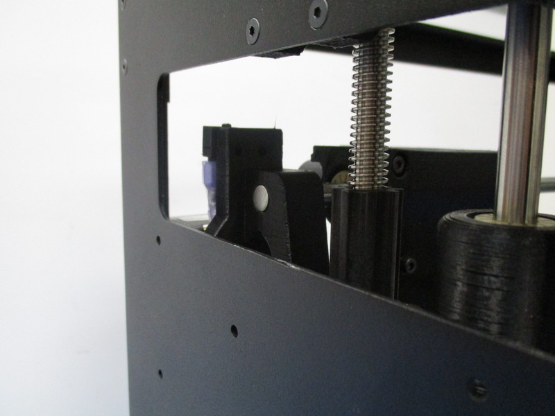
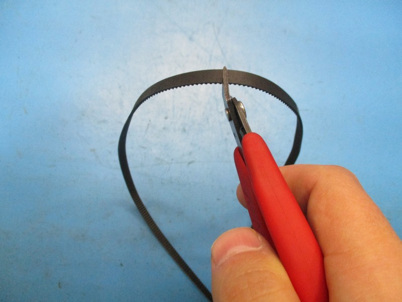
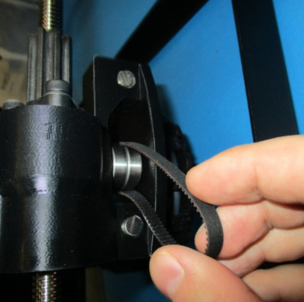
Cut the timing belt with a perpendicular cut to the edge of the belt resulting in a long open belt
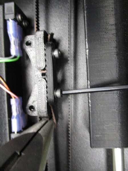
Loop the belt around one of the belt mount post as pictured
Fasten one side of the Belt clamp (PP-GP261_v1.1) to secure the belt to the belt mount post with a M3 x 12 mm socket head cap screw with M3 washer using a 2.5 mm hex driver, torque to 3 in*lbs
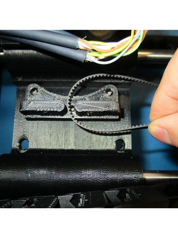
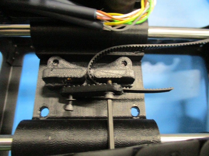
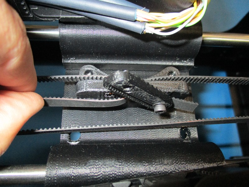
Run the timing belt with the teeth on the inside around the timing pulley, then run the timing belt around the idler bearings and back to the belt mount
Loop the belt around the unused belt mount post
Grab the loose end of belt with a pair of needle nose pliers and pull the belt tight, fasten the other side of the Belt clamp (PP-GP261_v1.1) to the Carriage Assembly with a M3 x 12 mm socket head cap screw with M3 washer using a 2.5 mm hex driver, torque to 3 in*lbs
Use the 508C Sonic Tension Meter to check the tension in the belt (see OHAI …)
The tension should be between 23-27 Newtons.
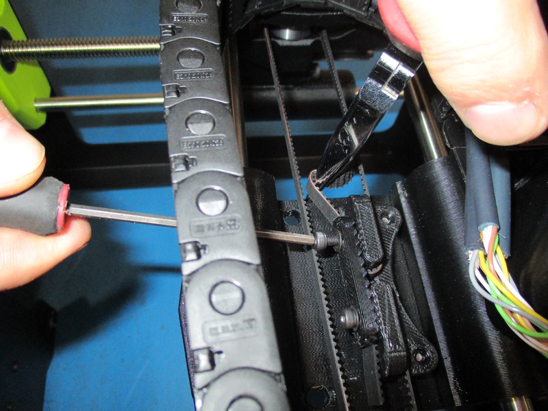
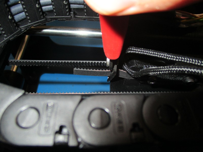
Trim the excess timing belt, leaving about 20mm on each side.


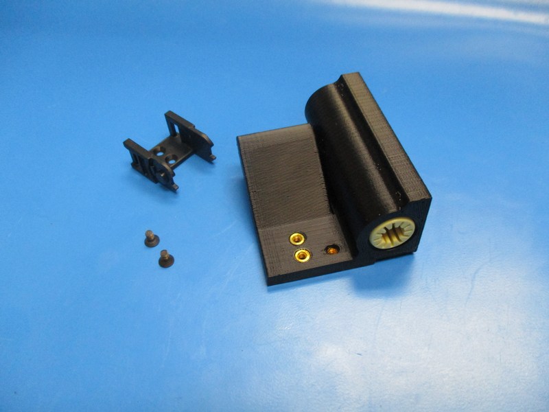
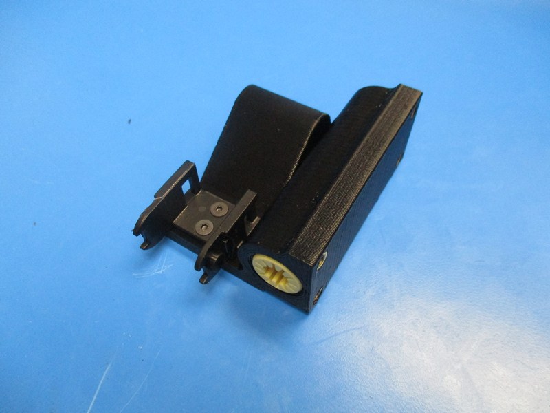
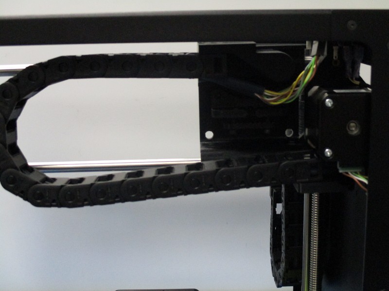
From the Extruder cable/ cable chain assembly remove the chain mount (last segment of the chain)
With 2x- M3x 6 FHSC attach the X carriage cable assembly chain mount to the Upper bearing holder. Tighten screws (~5in*lbs) See break out images of Chain Mount and Upper bearing holder, upper bearing holder comes already attached to the X carriage assembly
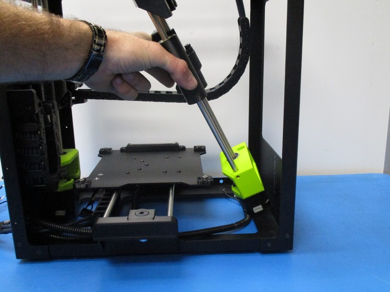
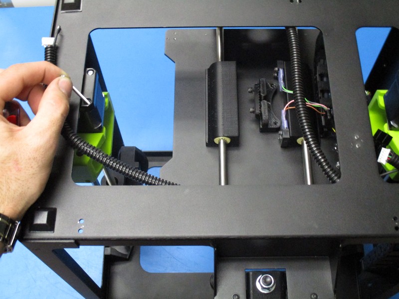
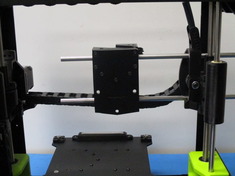
Slide the two smooth rods through the X End idler assembly and the X carriage assembly as pictured
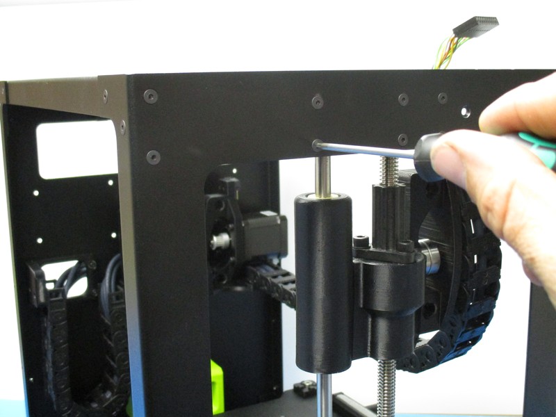
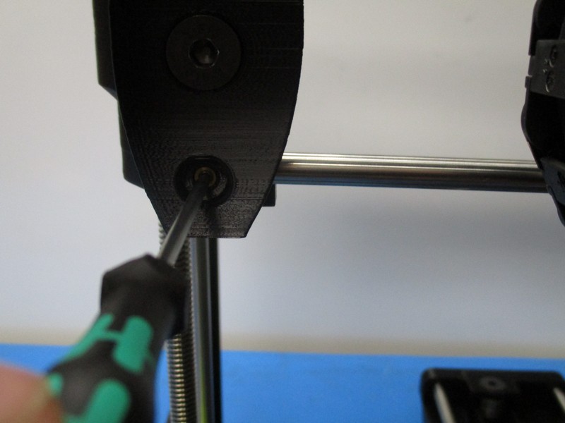
Align ends of the smooth rods flush with the sides of the X End Motor, tighten down the four M3 set screws, torque to 2in*lbs
Check to see if the X carriage assembly runs freely
Attach the X/extruder harness to the X carriage assembly with two M3 x 6 flat-head socket cap Screw using a 2.0 mm hex diver, torque to 5 in*lbs
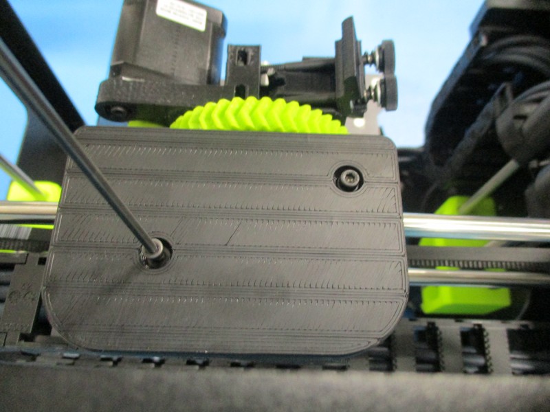
Attach the X timing belt to the belt mount on the X Carriage, tighten the M3 x 12 mm socket head cap screw with M3 washer using a 2.5 mm hex driver, torque to 3 in*lbs
Run the timing belt with the teeth on the inside around the timing pulley, then run the timing belt around the idler bearings and back to the belt mount. Feed the timing belt through the belt mount. Use the needle nose pliers to tension the belt, tighten the belt mount's M3 x12 socket head cap screw with a M3 washer using a 2.5 mm hex driver, torque to 3 in-lbs
Use the 508C Sonic Tension Meter to check the tension in the belt
The tension should be between 23-27 Newtons.
Trim the excess timing belt, leaving about 20mm on each side.
Cut the timing belt with a perpendicular cut to the edge of the belt resulting in a long open belt
Loop the belt around one of the belt mount post
Fasten one side of the Belt clamp (PP-GP261_v1.1) to secure the belt to the belt mount post with a M3 x 12 mm socket head cap screw with M3 washer using a 2.5 mm hex driver, torque to 3 in*lbs
Run the timing belt with the teeth on the inside around the timing pulley, then run the timing belt around the idler bearings and back to the belt mount
Loop the belt around the unused belt mount post
Grab the loose end of belt with a pair of needle nose pliers and pull the belt tight, fasten the other side of the Belt clamp (PP-GP261_v1.1) to the Carriage Assembly with a M3 x 12 mm socket head cap screw with M3 washer using a 2.5 mm hex driver, torque to 3 in*lbs
Use the 508C Sonic Tension Meter to check the tension in the belt (see OHAI …)
The tension should be between 23-27 Newtons.
Trim the excess timing belt, leaving about 20mm on each side.

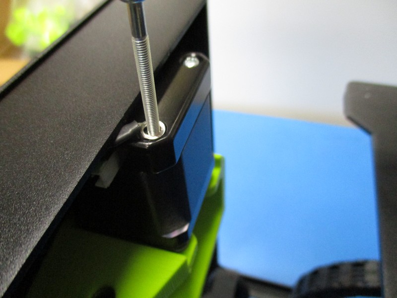
Attach the extruder to the X carriage using three M5 x 14 mm Socket Head Cap screws with black M5 washers with a 4mm hex diver Must use a straight 4mm driver and torque to 5 in*lbs, a ball end driver is not allowed
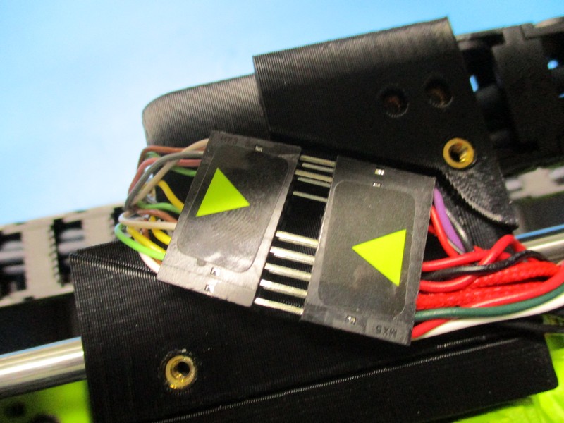
Plug the extruder cable 20 position male connector into the female connector on the X carriage so the alignment arrows on the connectors are pointing to each other
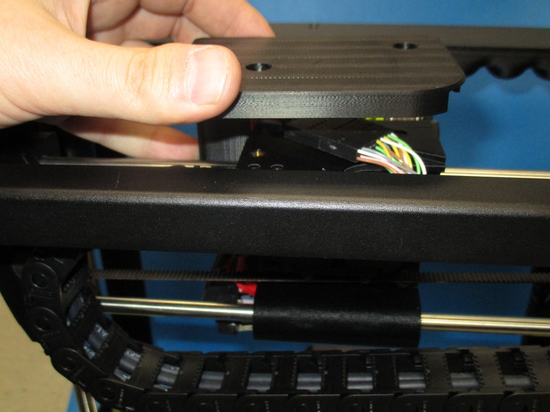
Place the extruder cable in the rectangular groove on top of the X carriage
Fasten the X-carriage cap to the top of the X Carriage using two M3 x 12 mm Socket Head Cap Screw with washer, ensuring wires are not being pinched by the X-Carriage cap; tighten the screws to no more than 5 in*lbs

Fasten the Spool arm bracket to the frame with four M3 x 6 mm Flat-Head Socket Cap Screws, tighten to 5 in*lbs