Open HardwareAssembly Instructions
Guides for installation and assembly of the LulzBot line of products made by FAME 3D LLC.
Guides for installation and assembly of the LulzBot line of products made by FAME 3D LLC.
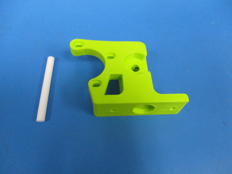
Gather parts:
Flexystruder body (PP-MP0200)
65mm of PTFE tubing (HD-TB0006)
Tools needed:
Drill press
6.5mm drill bit
3.5mm drill bit
8mm drill bit
3mm thick metal rod
Precision knife
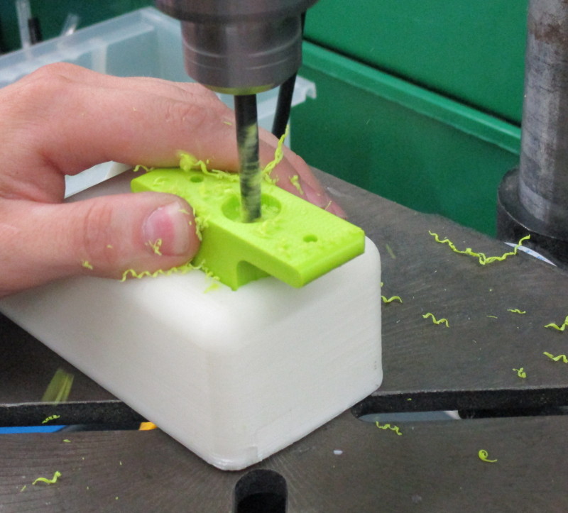
Instructions:
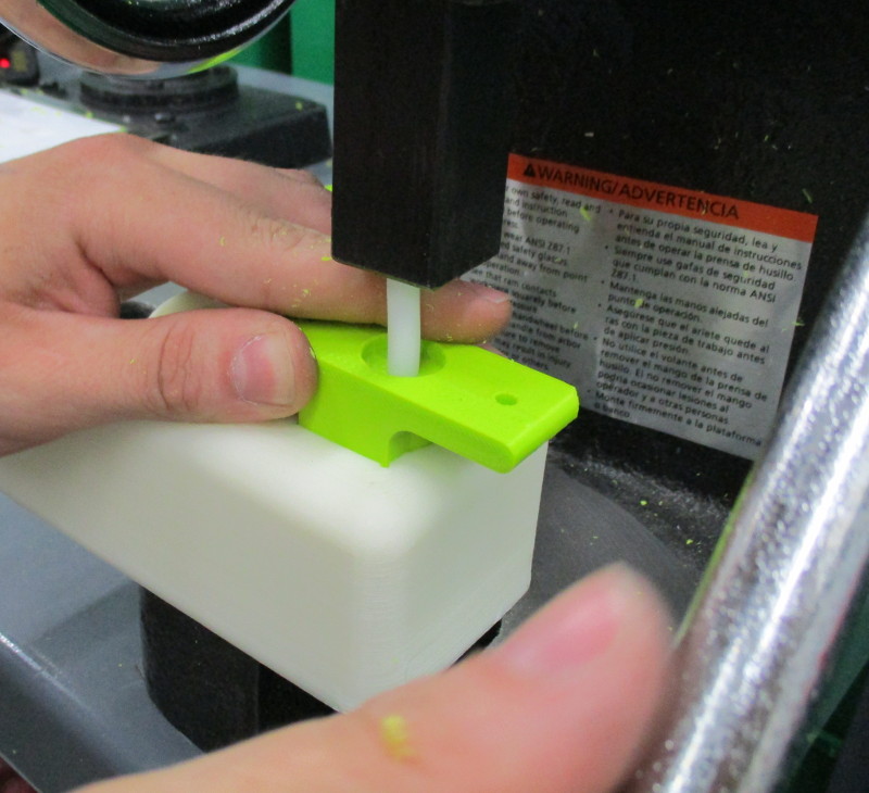
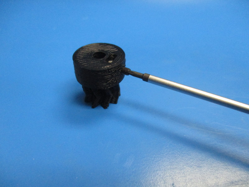
Starting at the bottom of the body, drill the out hole, that runs the length of the body, using the 6.5mm drill bit.
Press a 65mm long piece of PTFE tubing into the drilled hole through the bottom. The PTFE tubing needs to be flush with the indented hole.
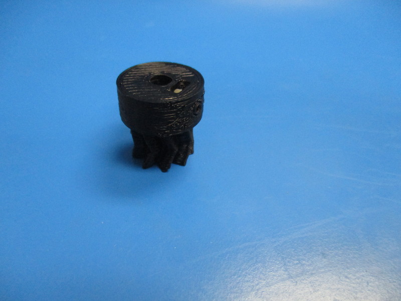
Note orientation of body.
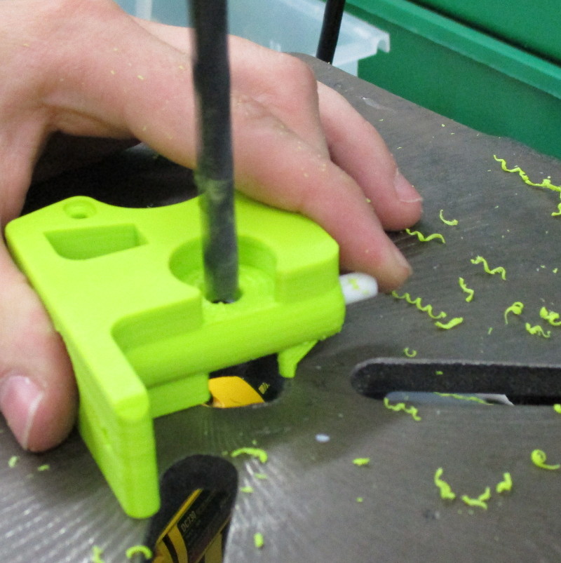
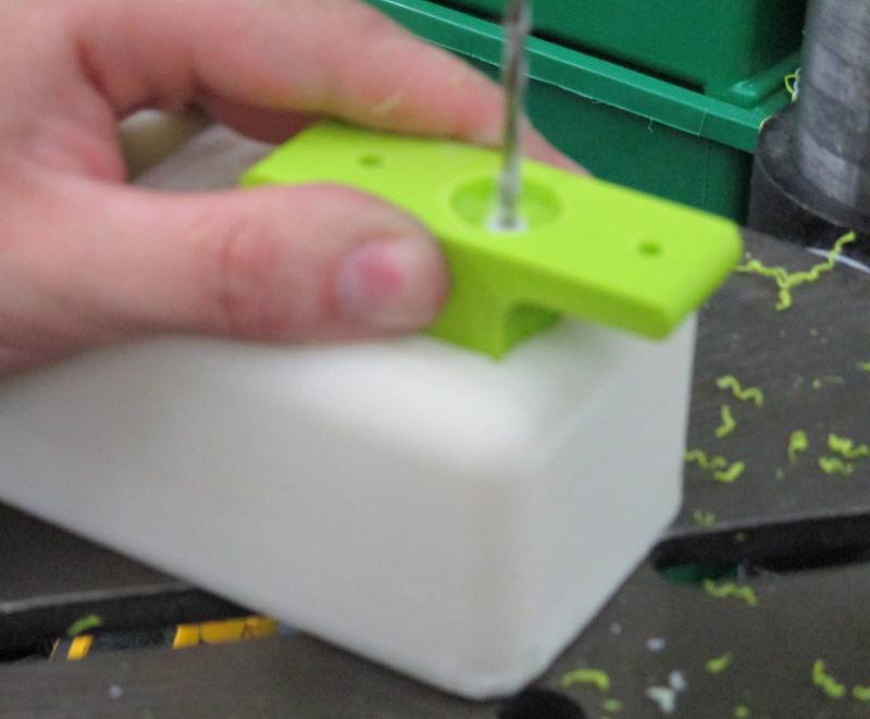
Drill the hobbed bolt hole out using the 8mm drill bit.
Drill the PTFE tubing out using the 3.5mm drill bit through the bottom of the body.
Slide the 3mm rod into the PTFE tubing.
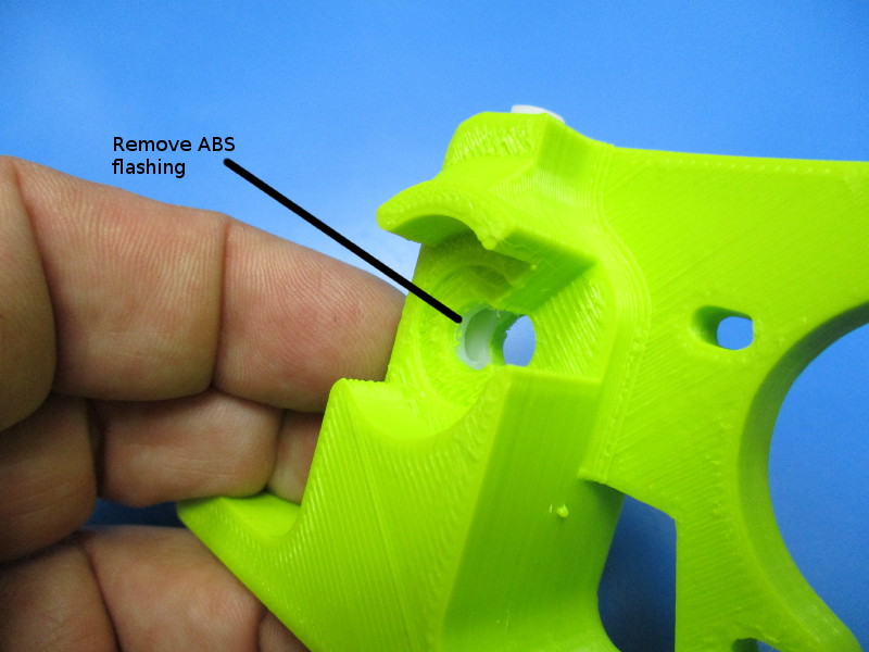
Clean out the flashing in the hobbed bolt hole using the precision knife.
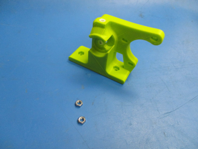
Gather parts
Flexystruder body with PTFE tubing
2x- M4 nut (HD-NT0011)
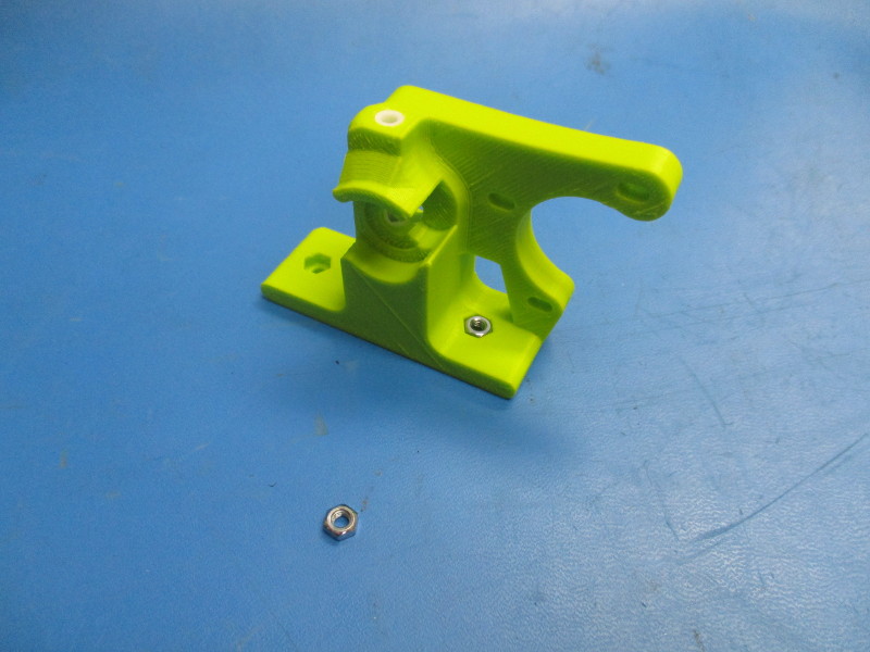
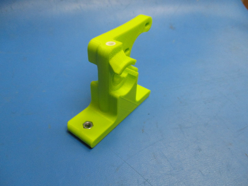
Instructions:
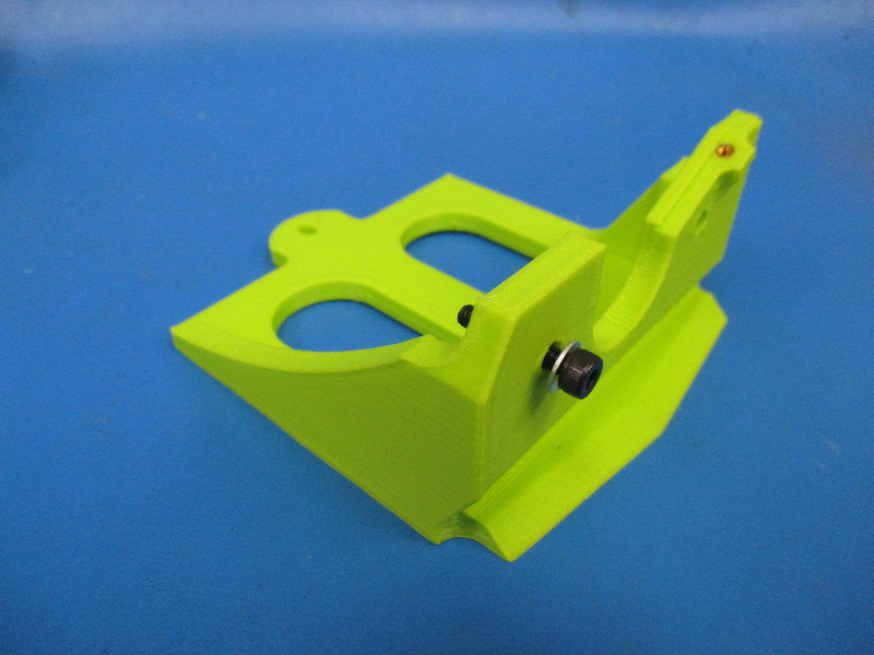
Insert both M4 nuts into the hexagon shaped socket at the base of the flexystruder body.
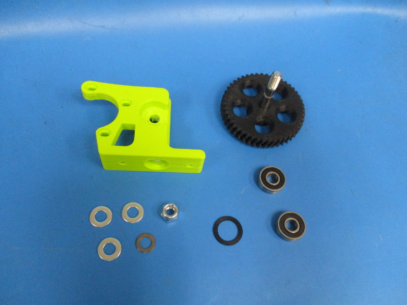
Gather parts
1x- Large herringbone, black (assembly)
1x- extruder washer (PP-GP0060)
2x- 608 bearing (HD-MS0282)
3x- M8 washer (HD-WA0006)
1x- 0.5mm shim (HD-WA0008)
1x- M8 nyloc nut (HD-NT0002)
Tools needed:
13mm wrench
Precision knife
Instructions:
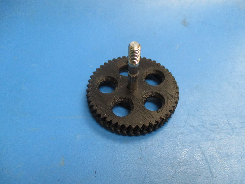
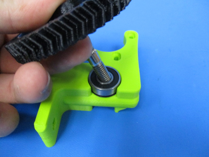
Install two M8 washers and one 0.5mm shim onto the hobbed bolt that is inserted into the large herringbone hear.
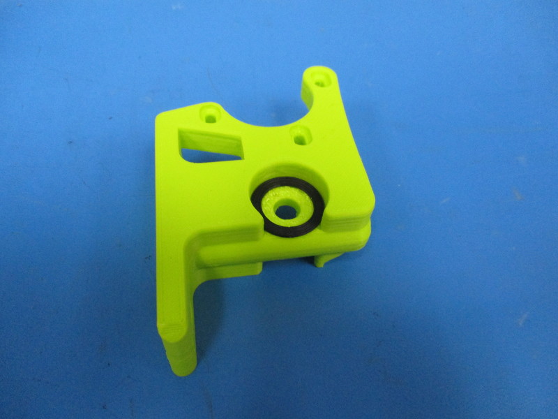
Lay the assembly onto its face. Install the extruder washer into the bearing pocket Install a 608 bearing on top of the extruder washer.
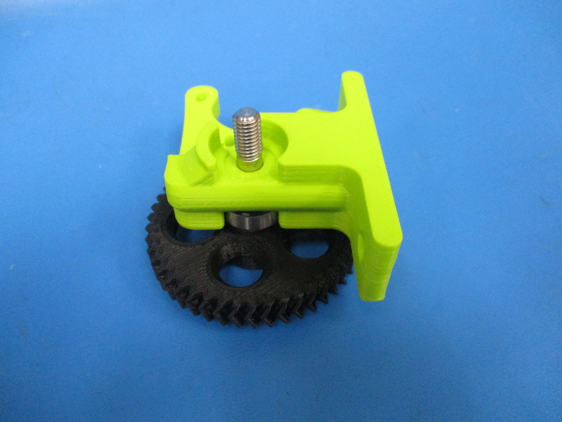
Install the large herringbone gear onto the flexystruder body by inserting the hobbed bolt through the bearing and body.
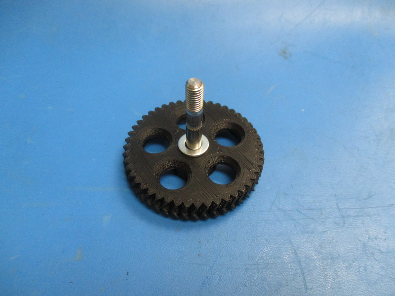
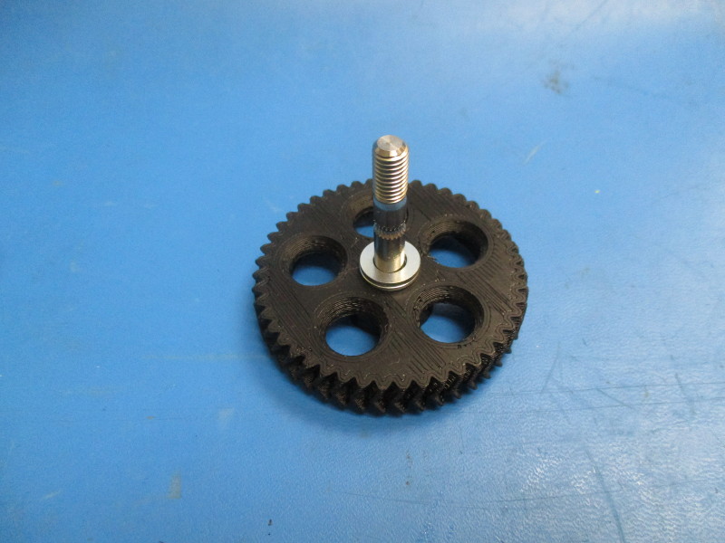
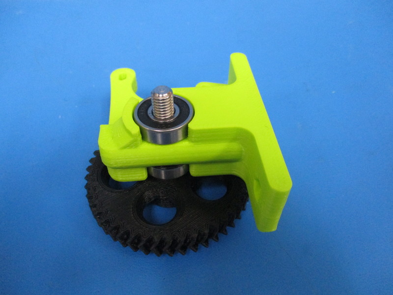
Flip the assembly over so the threaded portion of the hobbed bolt is visible. Install the second 608 bearing onto he hobbed bolt. Press the bearing down so that it sits in the bearing pocket.
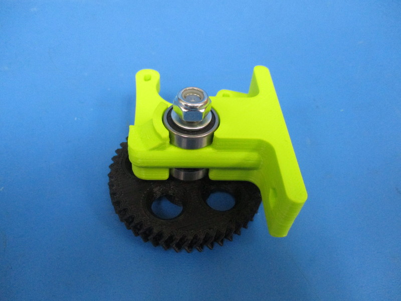
Install a M8 washer on top of the bearing. Install the M8 nyloc nut onto the threaded portion of the hobbed bolt.
Tighten the M8 nut using the 13mm wrench. The washer under the nut should not move freely or with slight force applied.
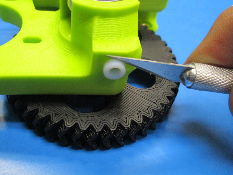
Cut off the excess PTFE tubing sticking out of the top.


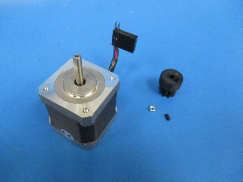
Gather parts
Small herringbone gear, black (PP-GP0062)
M3 nut (HD-NT0004)
Nema 17 stepper motor (EL-MT0001)
M3x4 set screw (HD-BT0012)
Tools needed:
Instructions:
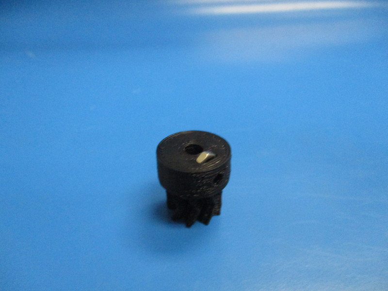
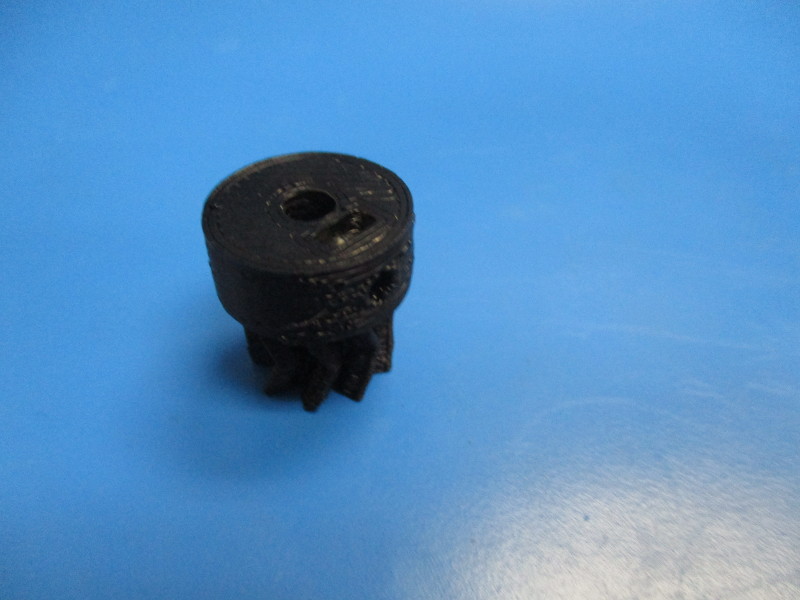
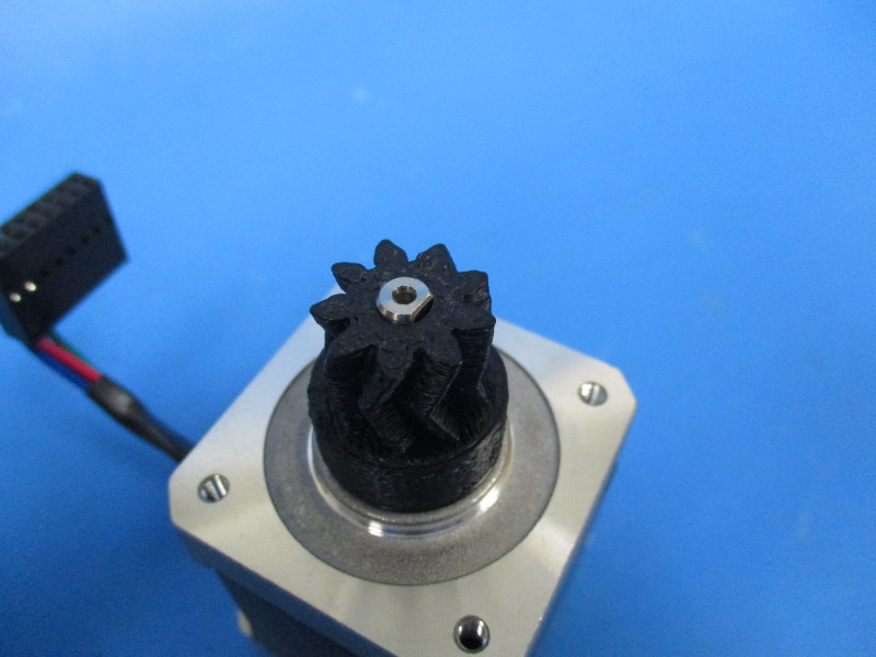
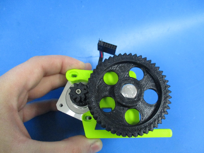
Set the small herringbone gear onto the flat face of the gear half so the nut slot is facing upwards. Insert the M3 nut into the nut slot. Use a driver to push it down into the slot to the nut hole and the hole on the side of the gear line up. Insert the M3x4 set screw into the hole aligned with the nut. Fasten the set screw until flush with the gear.
Install the small herringbone gear onto the Nema 17 stepper motor. Align the set screw with the flat section of the motor shaft. Finger tighten the set screw.

Gather parts
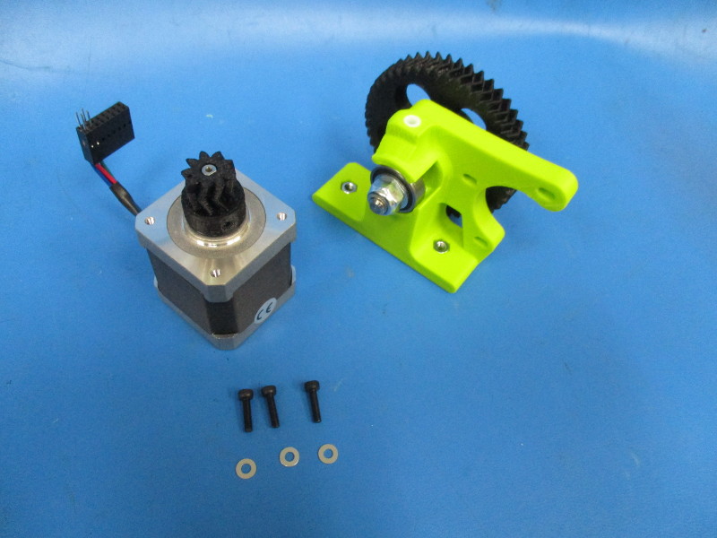
1x- Nema 17 motor (EL-MT0001)
3x- M3x12 SHCS (HD-BT0039)
3x- M3 washer (HD-WA0001)
1x- Body assembly
Tools needed:
Instructions:
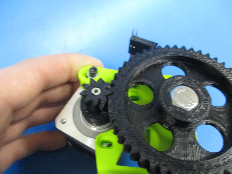
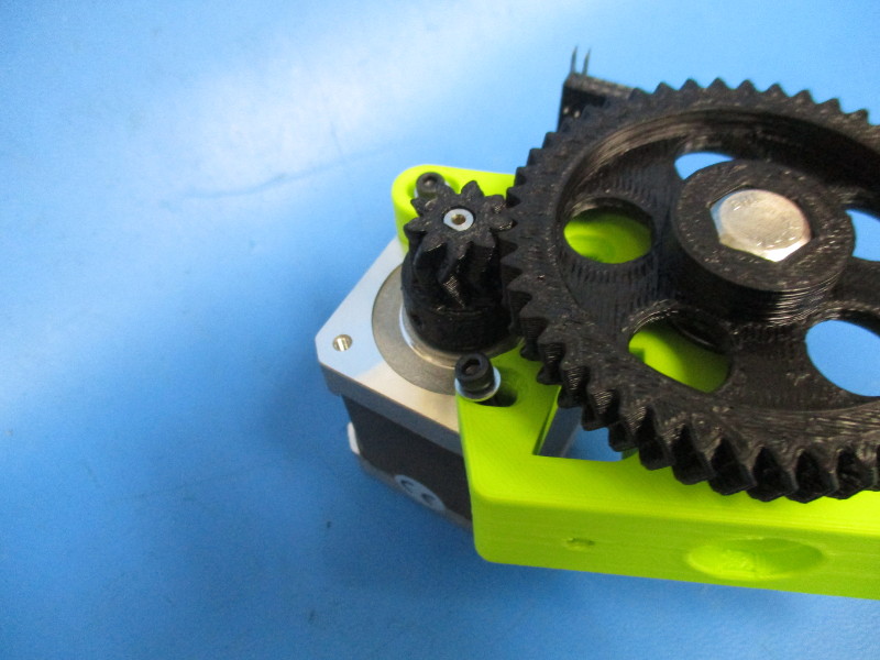
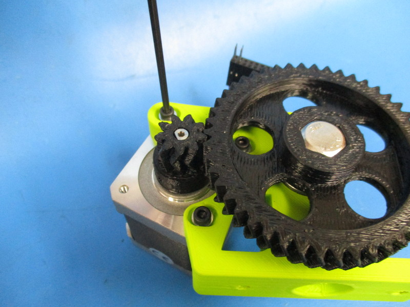
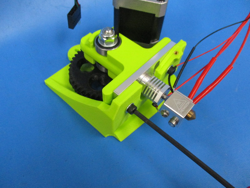
Mount the motor to the body (note the orientation of the motor and harness)
Place the M3x12 SHCS with black oxide in the three holes that line up with the tapped holes in the motor.
Note: the large gear and the small gear need to be mated together in a way that there is easy rotation but won't have any free movement known as “slap” between the gear teeth. To test for proper alignment of gears - tighten your screws down to 3 in/lbs, Hold the small gear firmly with your finger and thumb, and try to move the large gear back and forth to see if there is any small movement between the teeth of the gears. Rotate the large gear ¼ turn and repeat this process multiple times to ensure alignment. If there is movement the small gear and large gear need to be moved closer to each other. To do this you need loosen the M3 screws ¼ turn counter-clockwise and push the motor closer to the body. Repeat until you have desired the results, tighten screws once the fit is correct.) Torque to 3in*lbs


Gather parts
1x- extruder mount (assembly)
1x- mount plate (PP-MP0137)
1x- 0.6 hot end assembly
2x- M4x20 SHCS (HD-BT0010)
2x- M4 washer (HD-WA0005)
Tools needed:
2.5mm hex driver
Flashlight
Instructions:
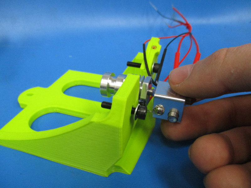
Insert the M4x20 screws with washers into the 4mm holes on the extruder mount.
Place the hot end onto the extruder mount between the two M4x20 screws.
Install the mount plate over the deep groove on the hot end.
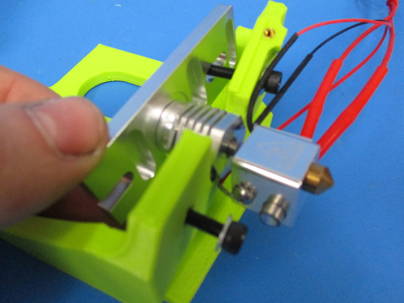
Install the hot end with the mount plate onto the extruder mount.
Install the flexystruder body onto the extruder mount. The M4x20 screws will line up with the 5mm holes that have the M4 nuts installed. Finger tighten.
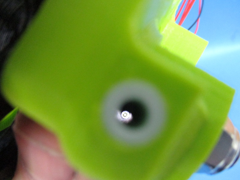
Shine a light through the nozzle. Look down the PTFE tubing and past the hobbed bold to see if everything is aligned. If everything is aligned there will be a circle all the way through to the hot end. If everything is not aligned, there will be a misshapen circle and the mount plate will need to be adjusted.
Torque the M4x20 screws to 8in*lbs.


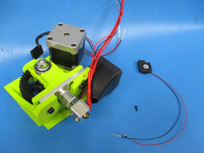
Gather parts
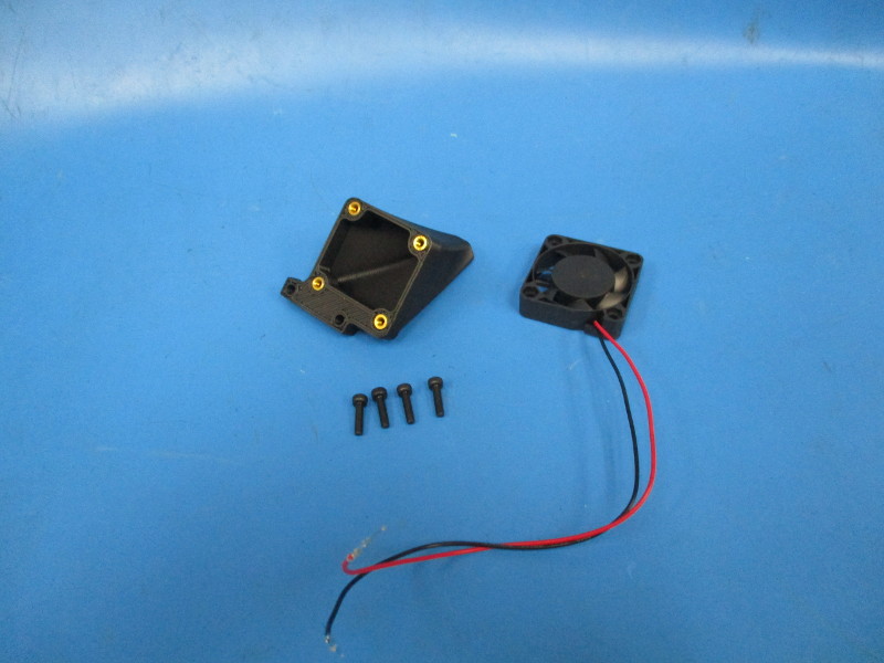
4x- M3x12 SHCS (HD-BT0039)
1x- Extruder fan mount (assembly)
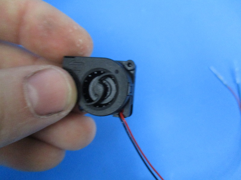
1x- 40mm 24v fan (assembly)
Tools needed:
Instructions:
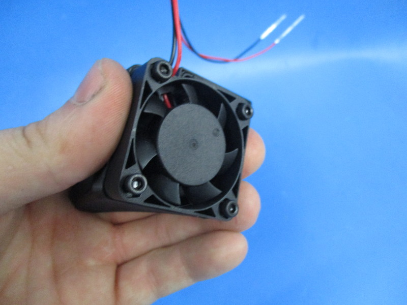
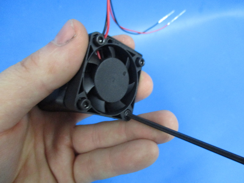
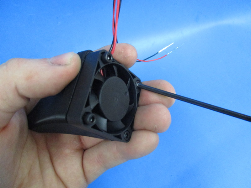
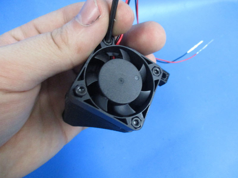
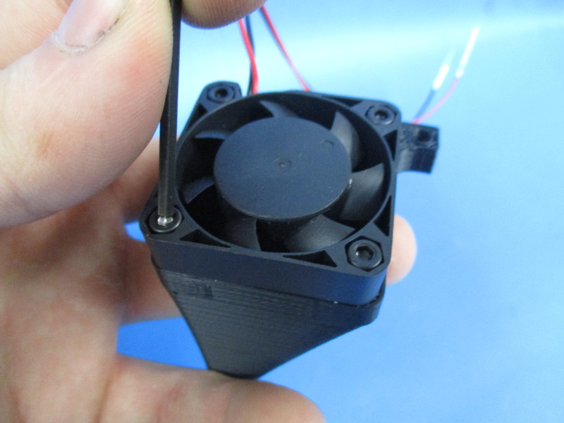
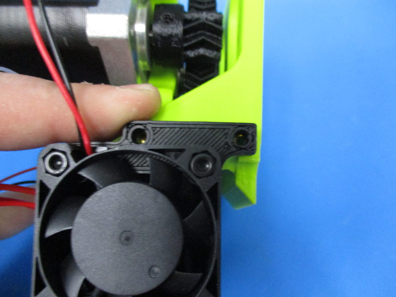
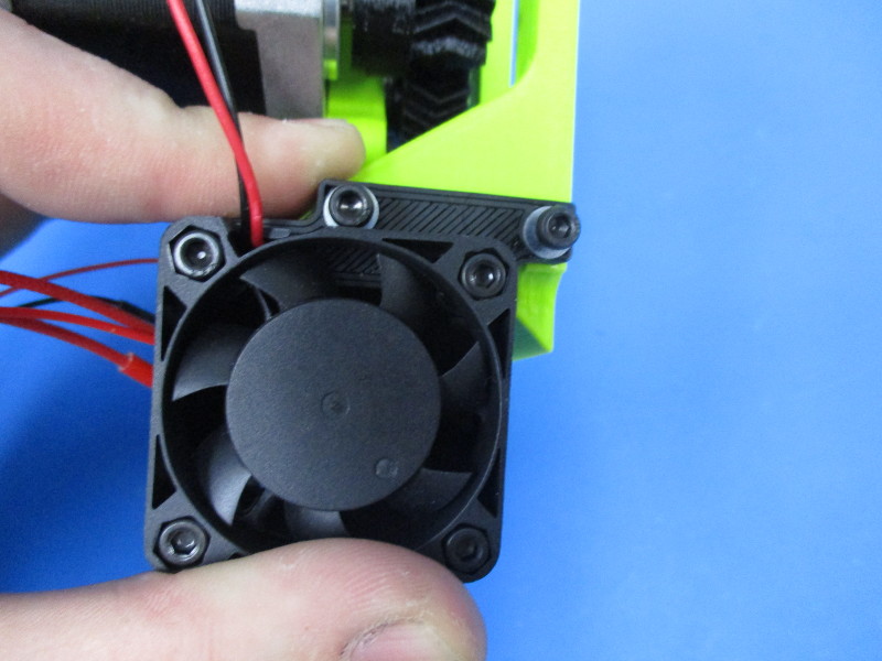
Align the hole in the corners of the 24v fan with the threaded inserts in the fan mount. Note the fans orientation on the fan mount and where the wires are coming off the fan.
Fasten the fan to the fan mount with the M3x12 screws. Torque to 5in*lbs

Gather parts
2x- M3x12 SHCS (HD-BT0039)
2x- M3 washer (HD-WA0001)
Tools needed:
Instructions:
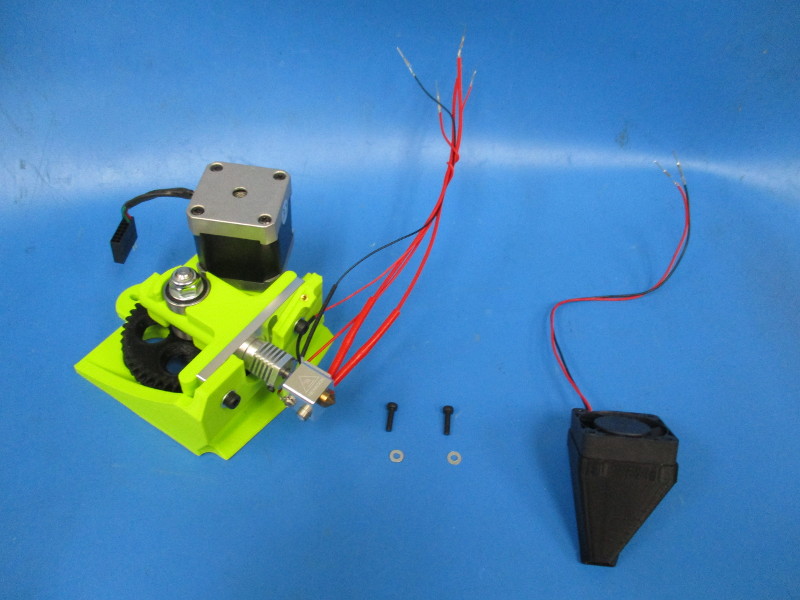
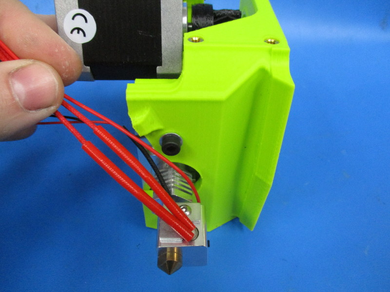
Pull the harnesses coming off the hot end toward the front of the extruder
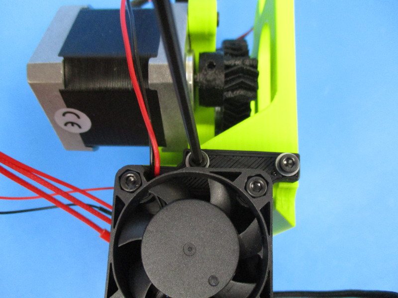
Align the two holes on the fan mount with the threaded inserts on the right side of the extruder mount. Fasten the fan mount to the extruder mount using two M3x12 screws with washers. Torque to 5in*lbs"

Gather parts
M2x6 SHCS (HD-BT0230)
Micro blower harness (assembly)
Tools needed:
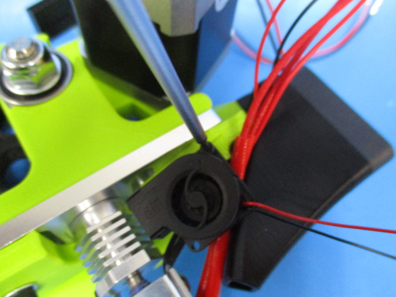
Instructions:
Insert the M2x6 screw into the top right corner of the micro blower. Align the screw with the threaded insert on the front of the extruder mount. Fasten the micro blower down to the extruder mount by torquing the M2x6 screw to 2in*lbs.
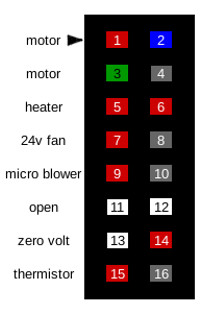
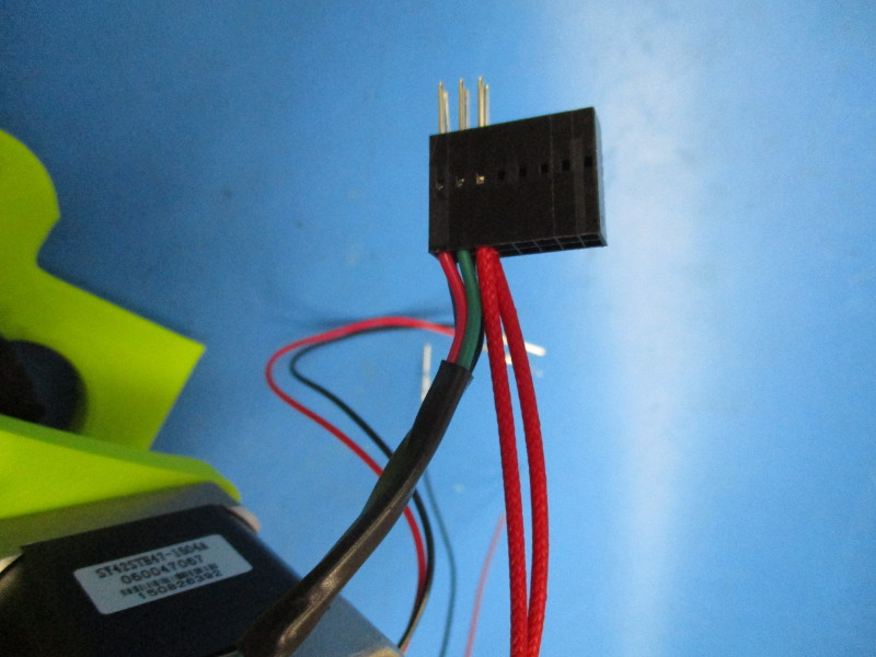
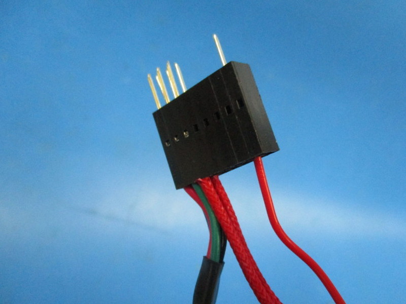
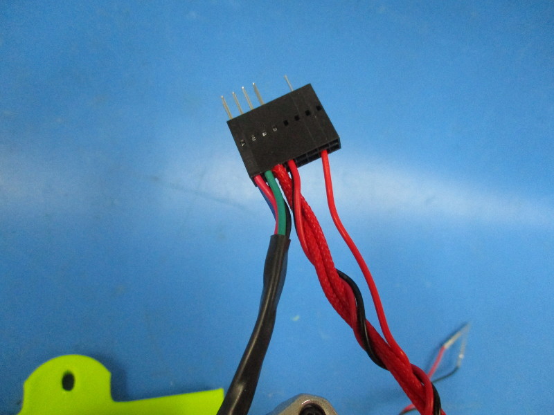
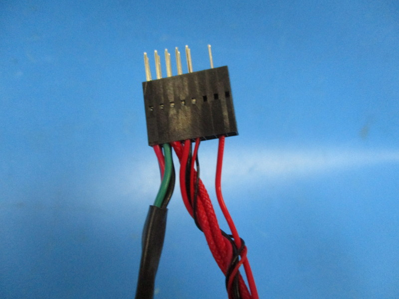
Connect the heater cartridge harness to the 16 pin connector in position 5 and position 6.
Run the Zero volt harness along the heater cartridge, and connect it in pin position 14.
Twist the 24v fan harness around the heater cartridge harness and zero volt harness 5 times. Connect the red wire into position 5 and the black wire into position 6
Twist the micro blower harness around the connected harnesses 6 to 7 times. Connect the red wire into position 7 and the black wire into position 8.
Twist the thermistor harness around the connected harnesses 3 to 4 times. Connect the red wire into position 15 and the black wire into position 16.

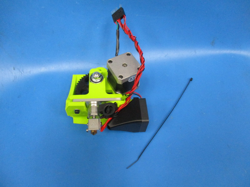
Gather parts
Instructions:
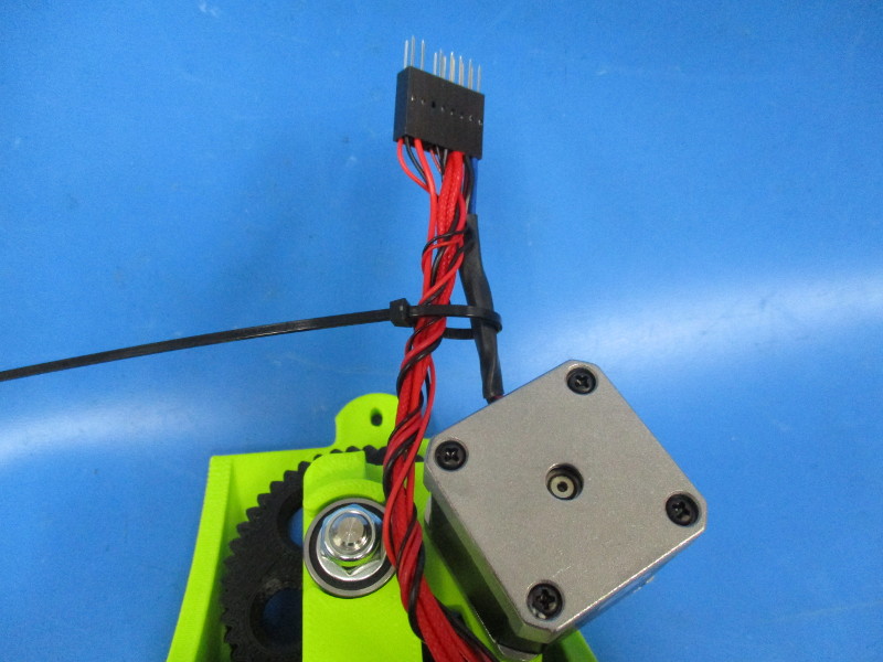
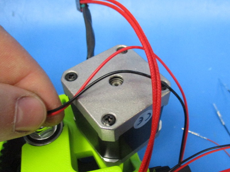
Adjust the harnesses so they rest against the left of the motor.
Cable tie the harnesses and the motor harness together halfway between the motor and the connector. Clip off excess cable tie