Open HardwareAssembly Instructions
Guides for installation and assembly of the LulzBot line of products made by FAME 3D LLC.
Guides for installation and assembly of the LulzBot line of products made by FAME 3D LLC.
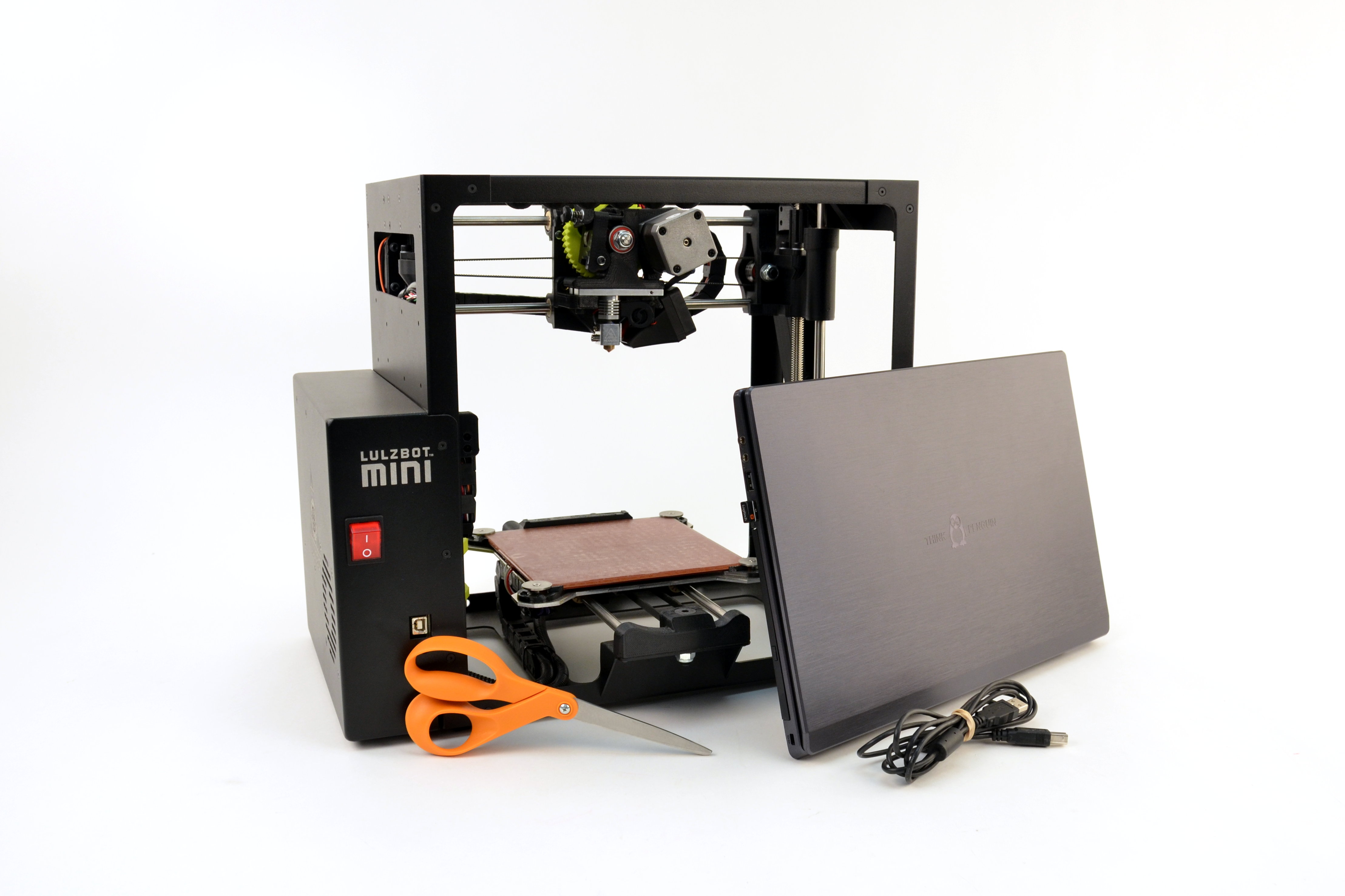
Follow the instructions below to quickly install your LulzBot Mini Aerostruder on a LulzBot Mini 3D Printer.
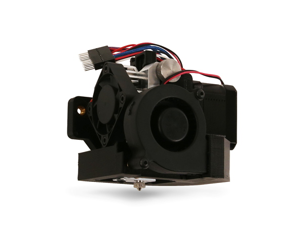
(1) LulzBot Mini Aerostruder Tool Head (Fully Assembled)
(1) PVA gluestick 0.77 oz
(1) Metric hex keys (2.5 mm, 4.0 mm)

You will also need
4A
Power on your LulzBot Mini 3D Printer.
4B
Connect your printer to your computer using the USB cable.
4C
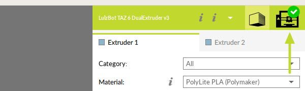
Press the Print Monitor control tab in the top right of Cura LulzBot Edition.
4D
Verify USB Device Available, as shown in image.
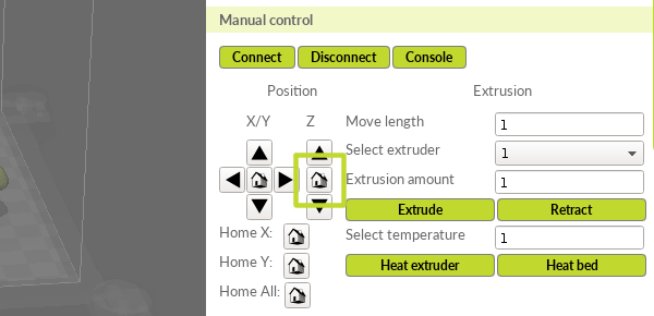
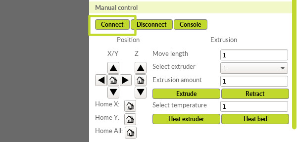
4E
Under "Manual Control" click Connect.
4F
Click the home icon below "Position Z".


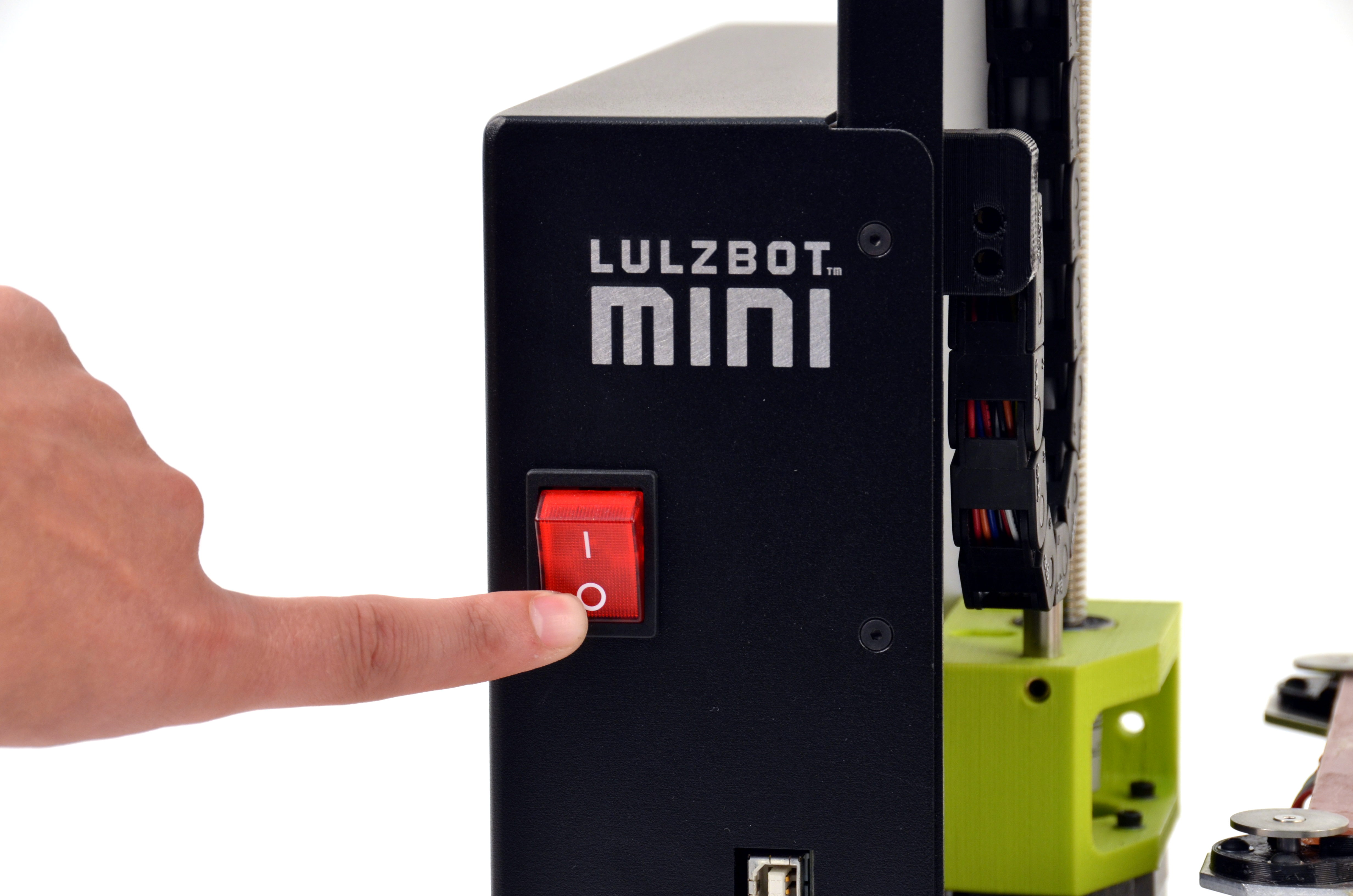
5A
Power off and unplug the power cord from the rear of the printer.
5B
Unplug the USB cable from the front of the printer.
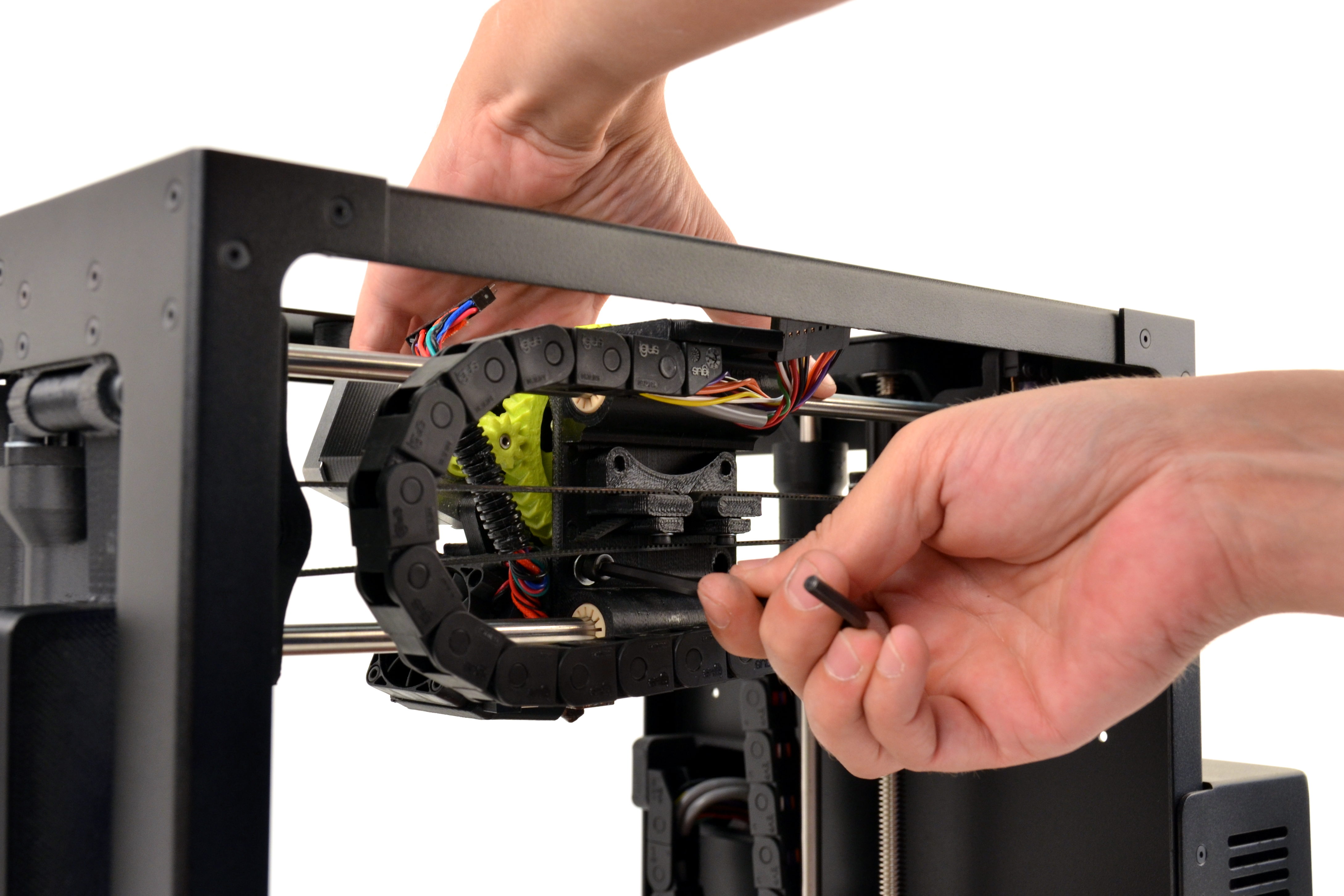
6A
Using your 2.5mm driver, unscrew the two M3 screws that secure the connector cover on the X-axis carriage, located on the top of the cover.
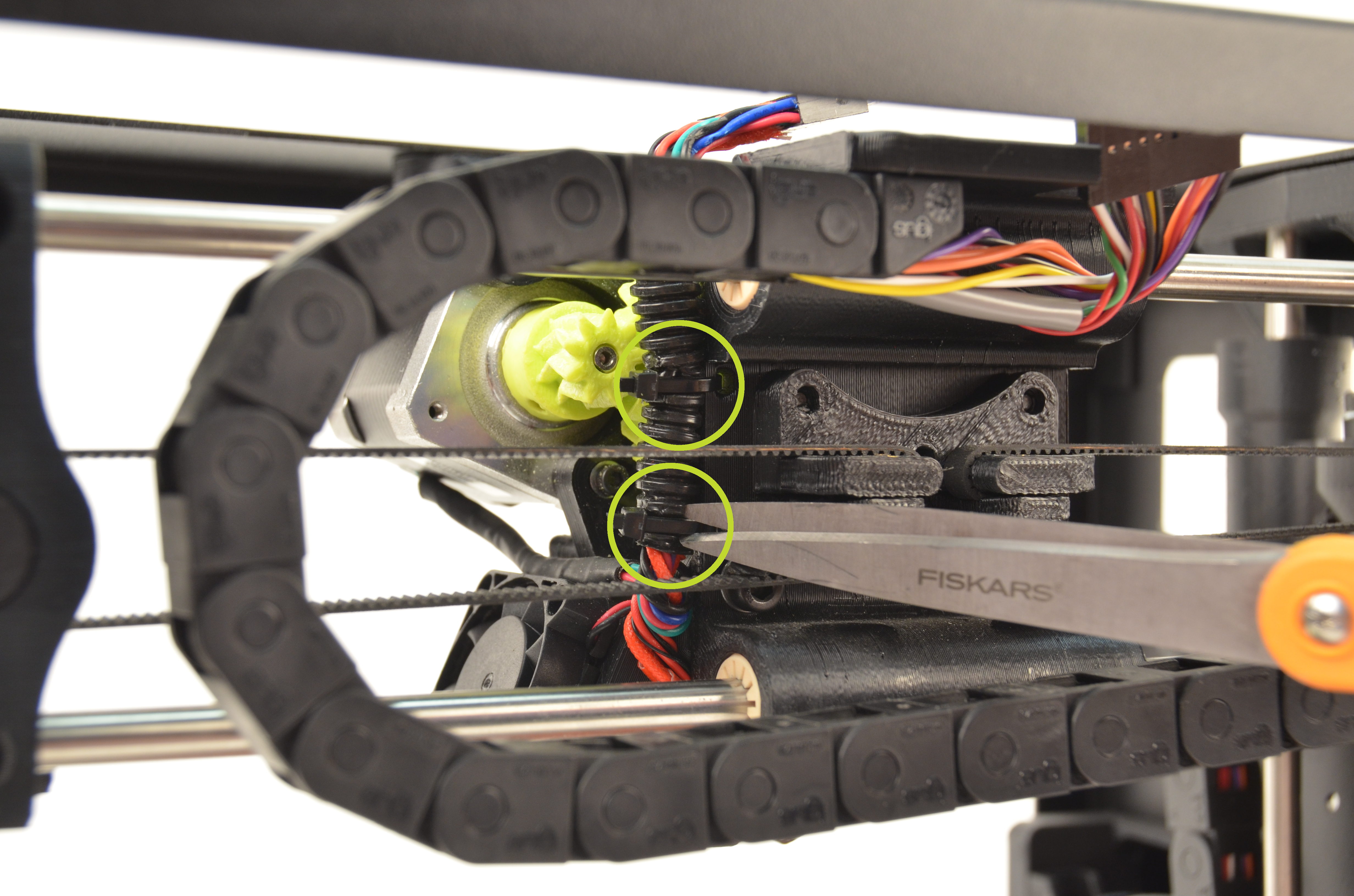
6B
Using the scissors, cut the two zip ties that secure the harness to the carriage.
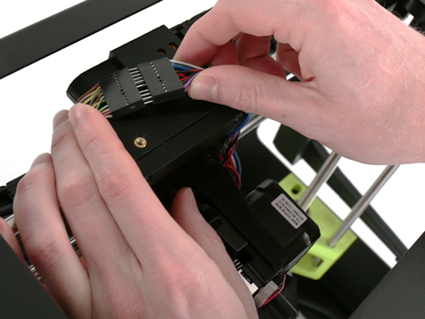
6C
Lift the connector away from the X-axis carriage.
6D
Unplug the tool head connector from the wiring harness.

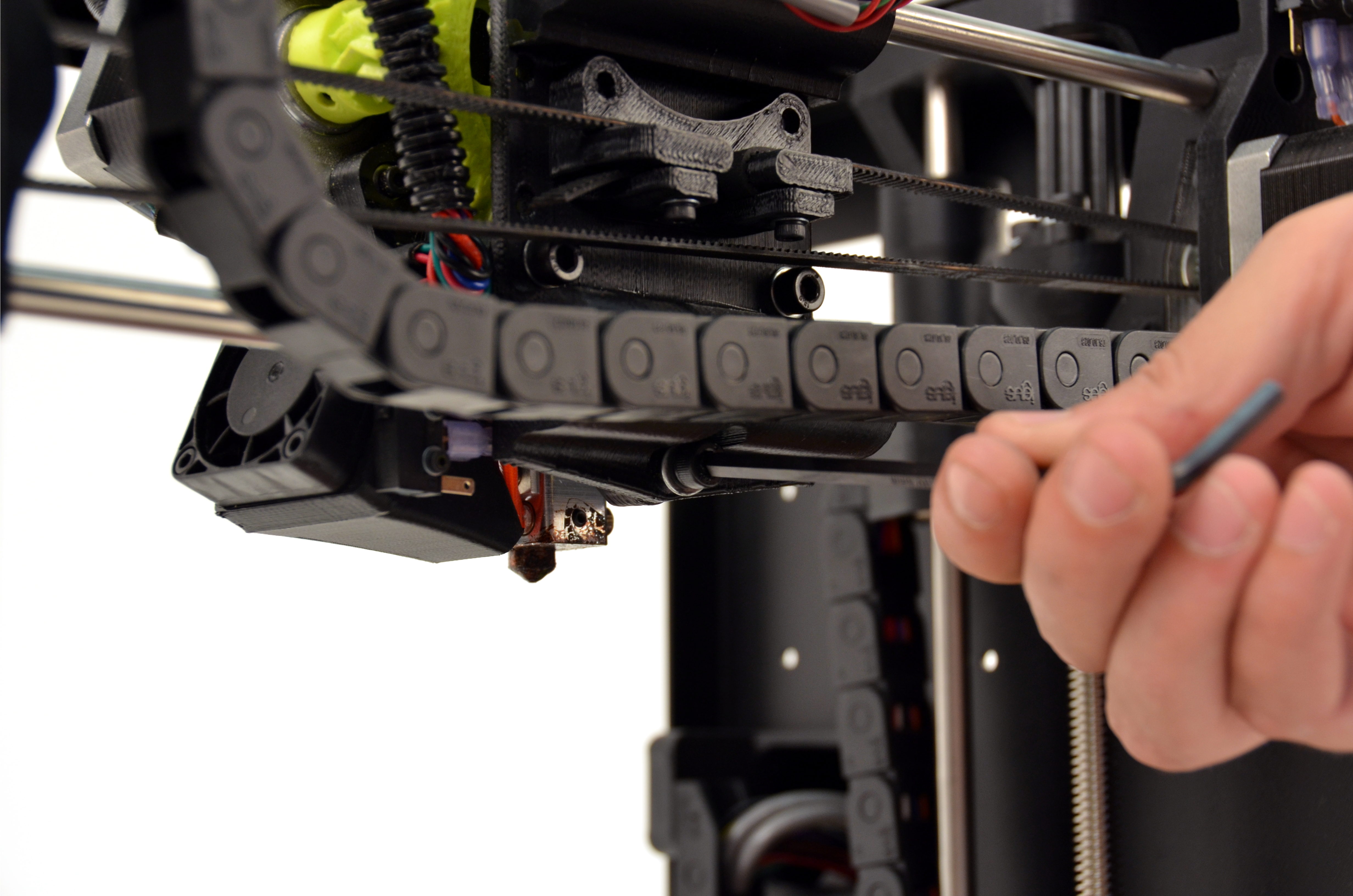
7A
The tool head is attached with three screws. The print surface can be damaged if the tool head is allowed to fall onto the print surface. With one hand, support the tool head while following removal steps below.
7B
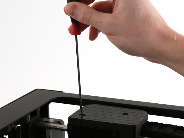
Using the 4mm hex key, unscrew the three M5 screws securing the tool head to the X-axis carriage. Remove the bottom screw first, followed by the remaining two screws.
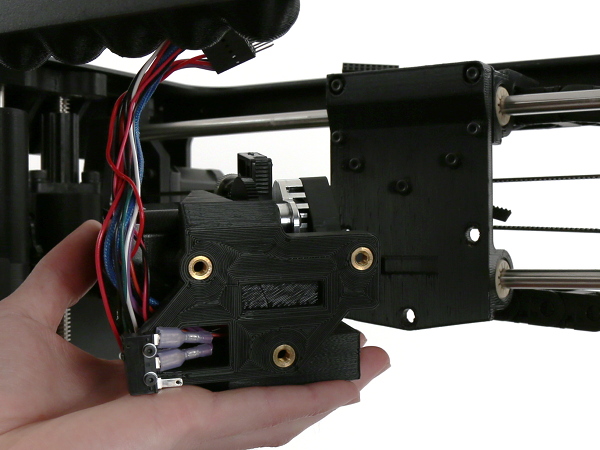
7D
Remove the tool head from the printer by lifting the tool head away from the printer.
Note: In previous versions of our tool heads, the Esteps (Extruder Steps Per Unit) were listed along the back of the tool heads for the customer to update. For the new Aerostruder tool head however, the Esteps are now set up within the firmware, and no manual updates are required.
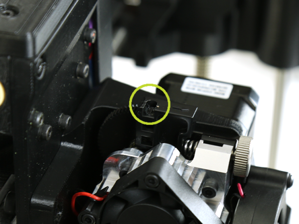
8A
Press the Aerostruder onto the X-axis carriage, aligning the tab with the cutout on the back of the new tool head.
8B
Secure it to the X-axis carriage by loosely screwing in the top two screws. Leave the top two screws loose.
8C
Install the last screw into the bottom of the X-axis carriage and fully tighten.
8D
Tighten the top two screws.
9A
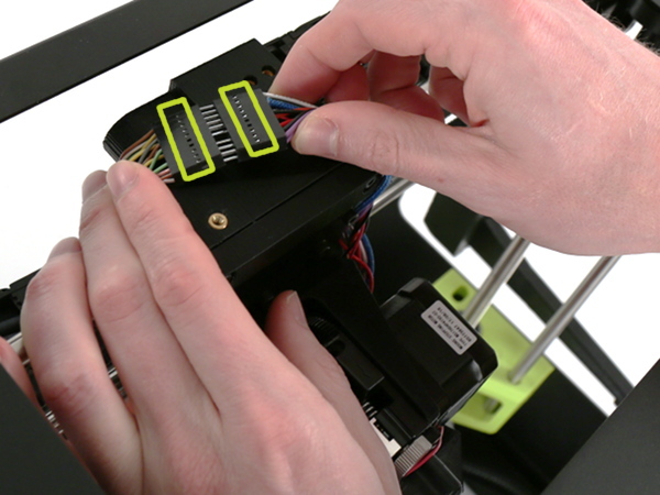
Pull foam off of 16-pin connector piece.
9B
Connect the two 16-pin connectors, making sure to match them based on the pins in the connector.
10A
Cover the connector with the connector cover and attach it to the X-axis carriage using the two M3 screws and the 2.5 mm hex key.
10B
Channel the wires together going to down the vertical pathway on the cover mount, and try not to pinch any of the wires when securing the cover. Slide down carefully into place, and hold while screwing in.
11A
Install the latest version of Cura LulzBot Edition. It is important to have the LulzBot Edition of Cura, as it has preset machine configuration profiles built into it.
11B
Cura LulzBot Edition is available from http://LulzBot.com/Cura.
11C
Plug in your LulzBot Mini 3D printer to the power supply and power on your 3D printer.
11D
Once powered on connect your 3D printer to your computer using the USB cable.
11E
Open Cura LulzBot Edition.
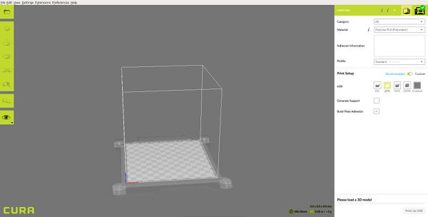
12A
Power on the printer.
12B
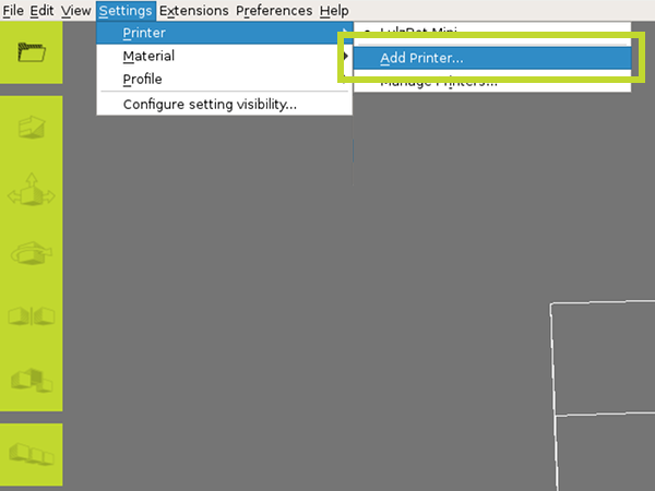
Select Settings dropdown > Printer > Add Printer
12C
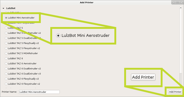
Select LulzBot Mini Aerostruder, and click Add Printer.
12D
Select Finish.

13A
Power on the printer.
13B
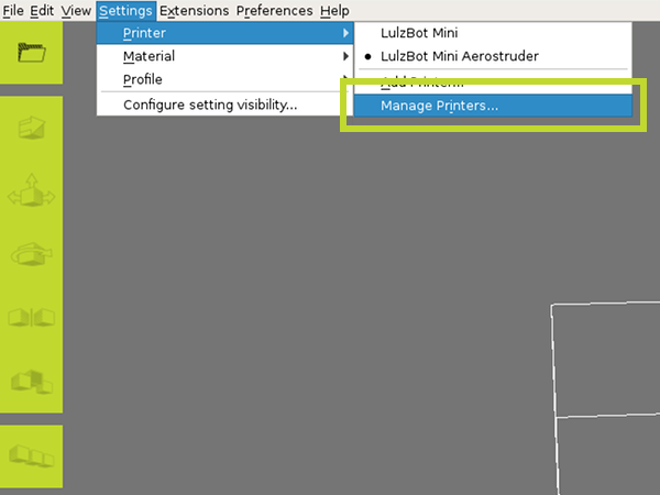
Select Settings dropdown > Printer > Manage Printers
13C
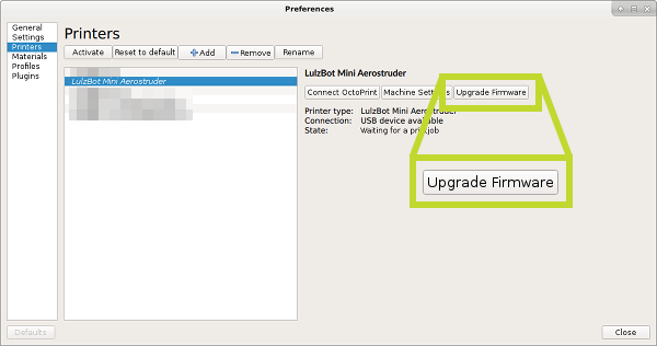
Confirm the LulzBot Mini Aerostruder is selected, and click Upgrade Firmware.
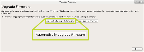
13D
Select Automatically Update Firmware.
14A
Select Print Monitor Control Tab in top right corner.
14B
Click Connect.
14C
Insert temperature as 205°C for Extruder 1. 205°C is the removal/print temperature for PLA (factory filament left in the tool head from calibration).
14D
Select Heat Extruder.


Note: Always heat the hot end to extrusion temperature before attempting to remove filament as this will prevent clogging or jamming in the filament chamber.
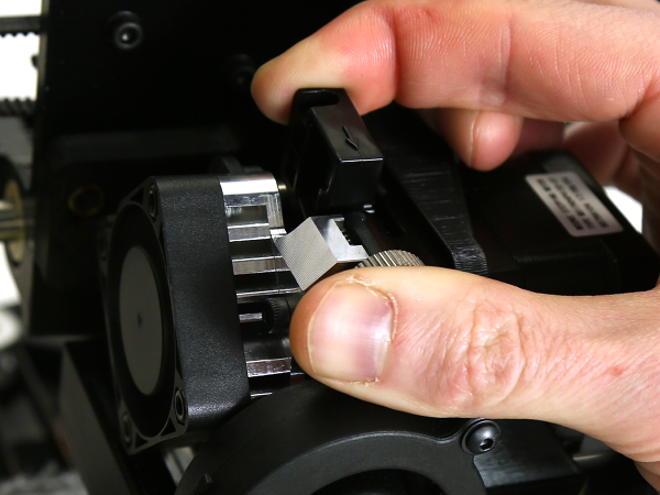
15A
Once hot end has reached the extrusion temperature of 205, remove test filament used during factory calibration by manually winding gear as shown in image. You can also do this by entering 60 for the Extrusion amount in Cura and clicking Retract.
15B
Once filament has retracted 60 mm, squeeze idler inwards, and pull the filament out. You may need to loosen the idler slightly by turning the silver idler wheel clockwise.
15C
Tighten the idler by turning the silver idler wheel counter-clockwise if loosened.

Note: If filament other than PLA is being used, refer to page 35 of the LulzBot Mini User Manual for recommended hot end temperatures. Repeat Step 14, entering in appropriate temperature value within range suggested for chosen filament before loading filament.
16A
Load your filament into Extruder 1. Squeeze the idler arm inward and insert the filament directly downwards.
16B
Rotate the gears by hand as shown in the image to help pull the filament into the tool head.
16C
Purge factory filament by continuing rotating gear by hand as shown in image until extrusion transitions into your filament of choice.


17A
You've now finished installation and are ready to start printing with flexible and rigid materials using your LulzBot Mini Aerostruder! Try performing a test print, such as the Rock2pus.