Open HardwareAssembly Instructions
Guides for installation and assembly of the LulzBot line of products made by FAME 3D LLC.
Guides for installation and assembly of the LulzBot line of products made by FAME 3D LLC.
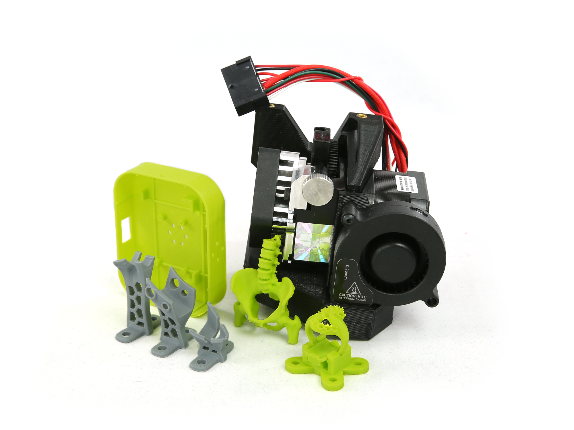
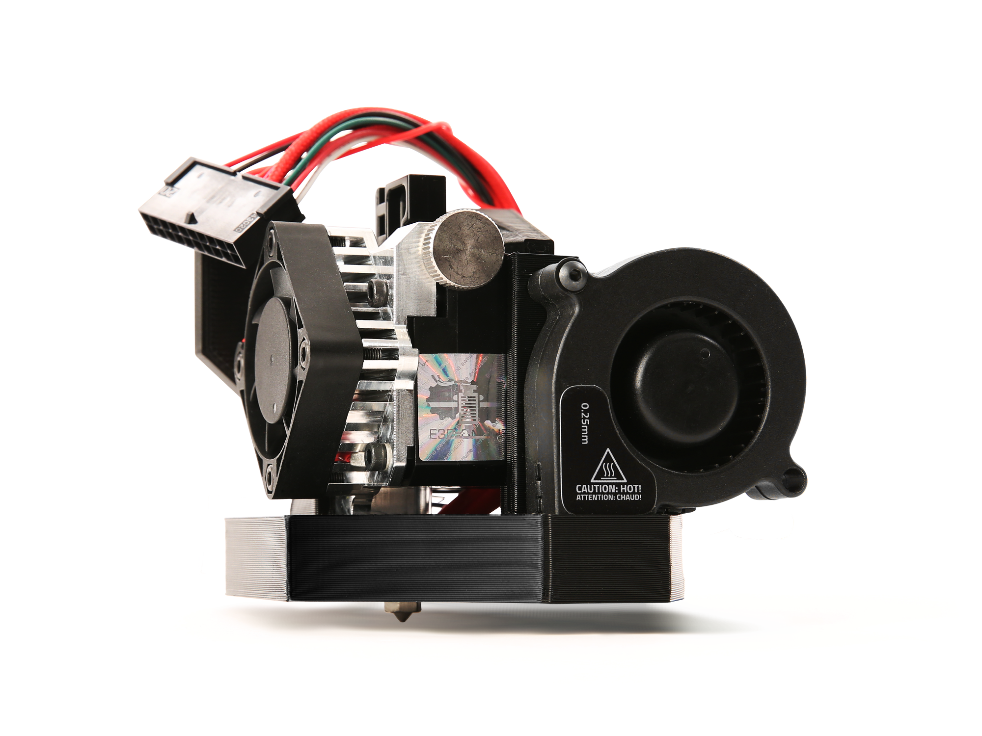
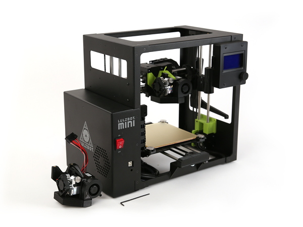
Follow the instructions below to quickly install your LulzBot SL Tool Head (Small Layer | Aerostruder v2 Micro) on a LulzBot Mini 2 3D Printer.
You will also need
4A
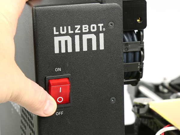
Power off and unplug the power cord from the rear of the printer.
4B
Unplug the USB cable from the front of the printer if installed.
5A
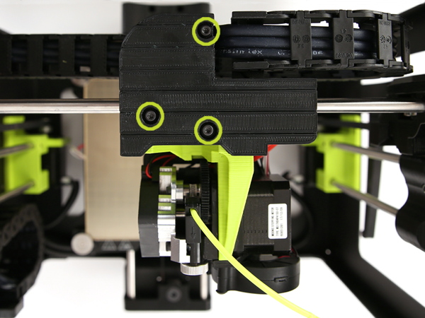
Using the 2.5 mm hex key included with your LulzBot Mini 2, remove the three M3 screws.
5B
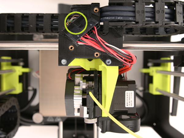
Lift off the cover, exposing the tool head connector.

Depress the retaining tab on the connector housing and gently wiggle the connector free. Do not pull on the wires, only the connector housing.
7A
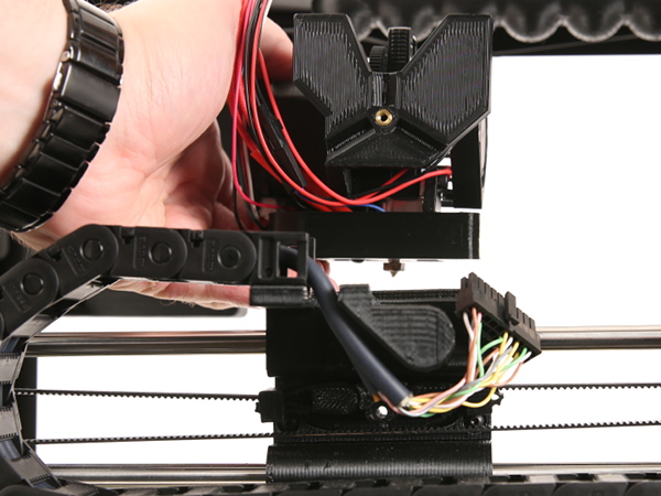
The tool head is attached with three screws. The print surface can be damaged if the tool head is allowed to fall onto the print surface. With one hand, support the tool head while following removal steps below.
7B
Using the 2.5mm hex key, unscrew the three M5 screws securing the tool head to the X-axis carriage. Remove the rear screw first, followed by the remaining top two screws.
7C
Remove the tool head from the printer by moving the tool head away from the printer.
Note: In previous versions of our tool heads, the Esteps (Extruder Steps Per Unit) were listed along the back of the tool heads for the customer to update. For the new Aerostruder tool head however, the Esteps are now set up within the firmware, and no manual updates are required.
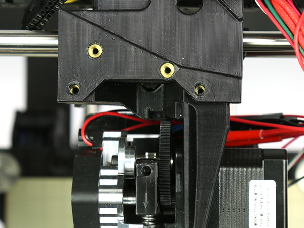
8A
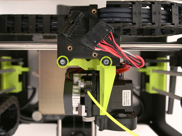
Press the tool head onto the X-axis carriage, aligning the cutouts on the back of the new tool head. Do not pinch any wires between the mount and the carriage.
8B
Secure it to the X-axis carriage by loosely screwing in the top two screws. Leave the top two screws loose.
8C
Loosely screw in the last screw through the rear of the X-axis carriage.
8D
Tighten the top two screws.
8E
Tighten the rear screw.
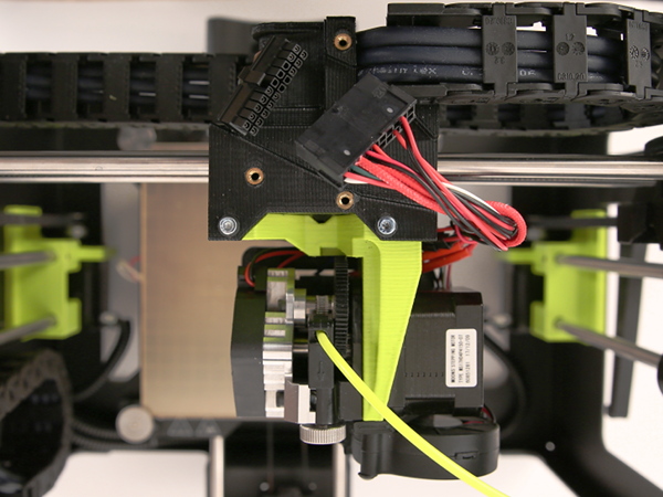
Connect the two connectors, making sure to fully seat the connectors until they lock.


10A
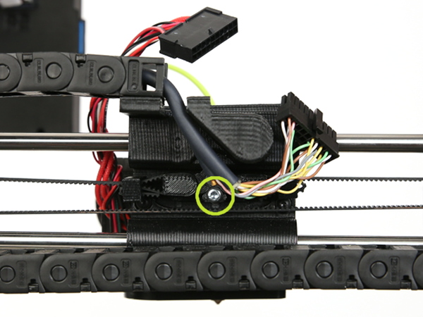
Cover the connector with the connector cover and attach it to the X-axis carriage using the three M3 screws and the 2.5 mm hex key.
10B
Channel the wires together going to down the vertical pathway on the cover mount, and try not to pinch any of the wires when securing the cover. Slide down carefully into place, and hold while screwing in.

11A
Install the latest version of Cura LulzBot Edition. It is important to have the LulzBot Edition of Cura, as it has preset machine configuration profiles built into it.
11B
Cura LulzBot Edition is available from http://LulzBot.com/Cura.
11C
Plug in your LulzBot Mini 2 3D printer to the power supply and power on your 3D printer.
11D
Once powered on connect your 3D printer to your computer using the USB cable.
11E
Open Cura LulzBot Edition.

12A
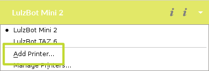
In the top right-hand menu for Cura LE, Select the Settings drop-down arrow > Printer > Add Printer
12B
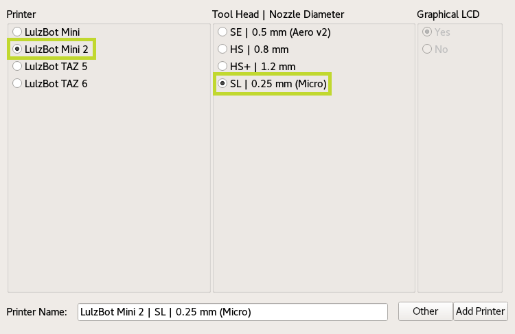
Select LulzBot Mini 2, SL | 0.25 mm (Micro), and click Add Printer.
12C
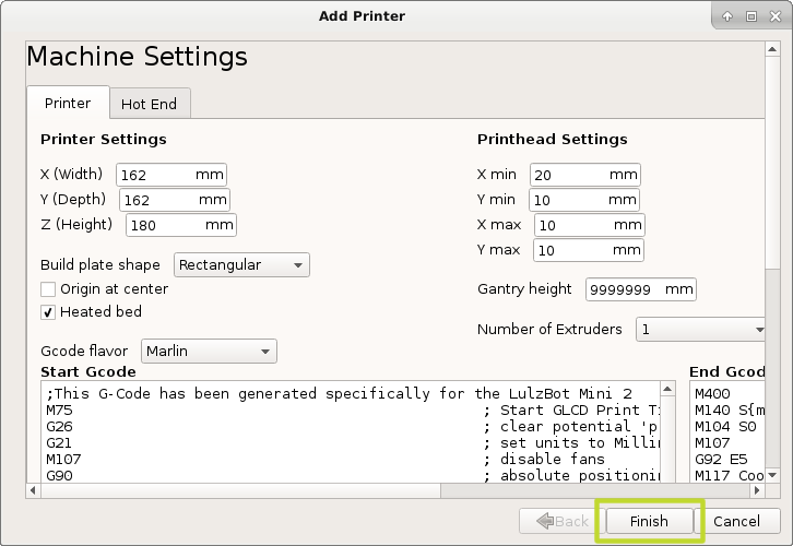
Select Finish.
13A
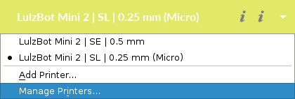
From the drop-down menu at the top right-hand side of Cura LE, Select Manage Printers
13B
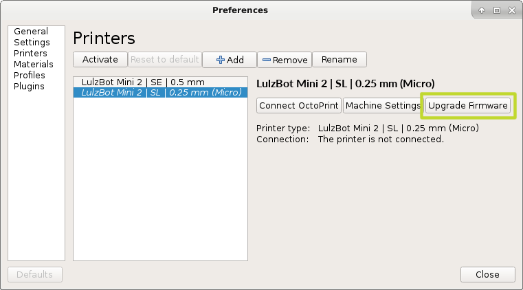
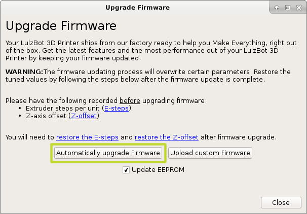
Confirm that the LulzBot Mini 2 | SL | 0.25 mm is selected, and click Upgrade Firmware.
13C
Select Automatically Update Firmware. The Update EEPROM checkbox should be checked by default. Close any dialog windows after the firmware has been updated.
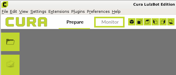
14A
Select Print Monitor Control Tab from the menu above the virtual print interface.
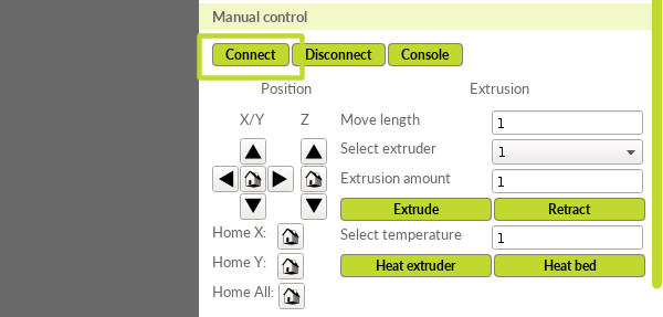
14B
Click Connect.
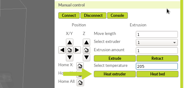
14C
Type 205 into the Select temperature field.
14D
Select Heat Extruder.
Note: Always heat the hot end to extrusion temperature before attempting to remove filament. If switching between different material types, set the hot end to the approximate average extrusion temperature of the two materials.
15A
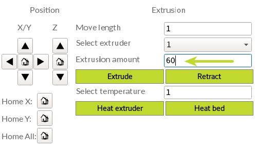
Once the hot end has reached the extrusion temperature of 205, remove the test filament used during factory calibration by entering 5 for the Extrusion amount in Cura LE. Click the Extrude button. Change the value to 60 and click the Retract button.
15B
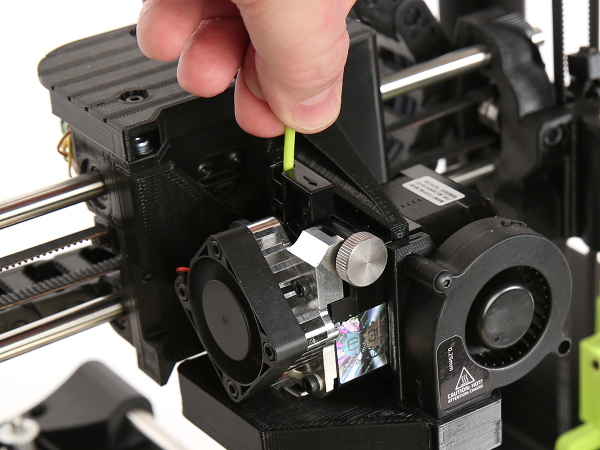
Once filament has retracted 60 mm, squeeze idler inwards, and pull the filament out. You may need to loosen the idler slightly by turning the silver idler wheel clockwise.
15C
Tighten the idler by turning the silver idler wheel counter-clockwise if loosened.

Filament Loading Tip: Cutting the filament at an angle will help with inserting into the extruder.
16A
Load the sample filament into the extruder. Squeeze the idler arm inward and insert the filament into the extruder filament guide.
16B
Enter 60 in Extrusion amount and click the Extrude button.
16C
Purge factory filament by continuing to select the Extrude button until the hot end extrudes material.
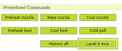
16D
Level the X-axis by clicking the Level X Axis button.
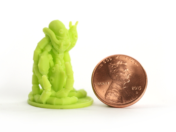
Your first print: the LulzBot Rocktomek: Download and Save
17a
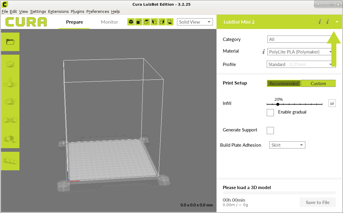
Load the RocktomekPose05.stl 3D model.
17b
Select the sample material: PolyLite PLA (Polymaker) and the Profile: High Detail.
17c
Press the Print via USB button to start your print!

You may need to fine tune your Z-axis offset, also known as Z-offset, to get the perfect first layer. Follow the instructions in the Advanced section of the LulzBot Mini 2 User Manual for detailed instructions.
More Information: LulzBot Mini 2 User Manual - Adjusting Z-offset
Adjust your Z-offset during the first layer of the print by following these steps:
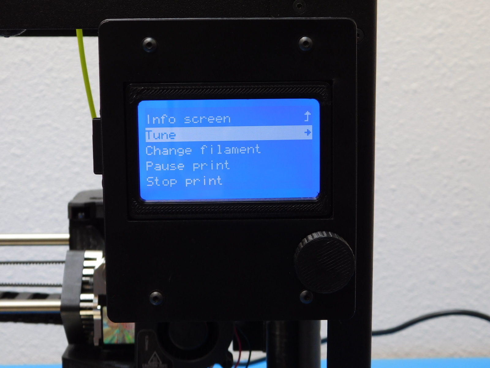
18A
Press in on the Graphical LCD Controller knob on the LulzBot Mini 2 and select Tune.
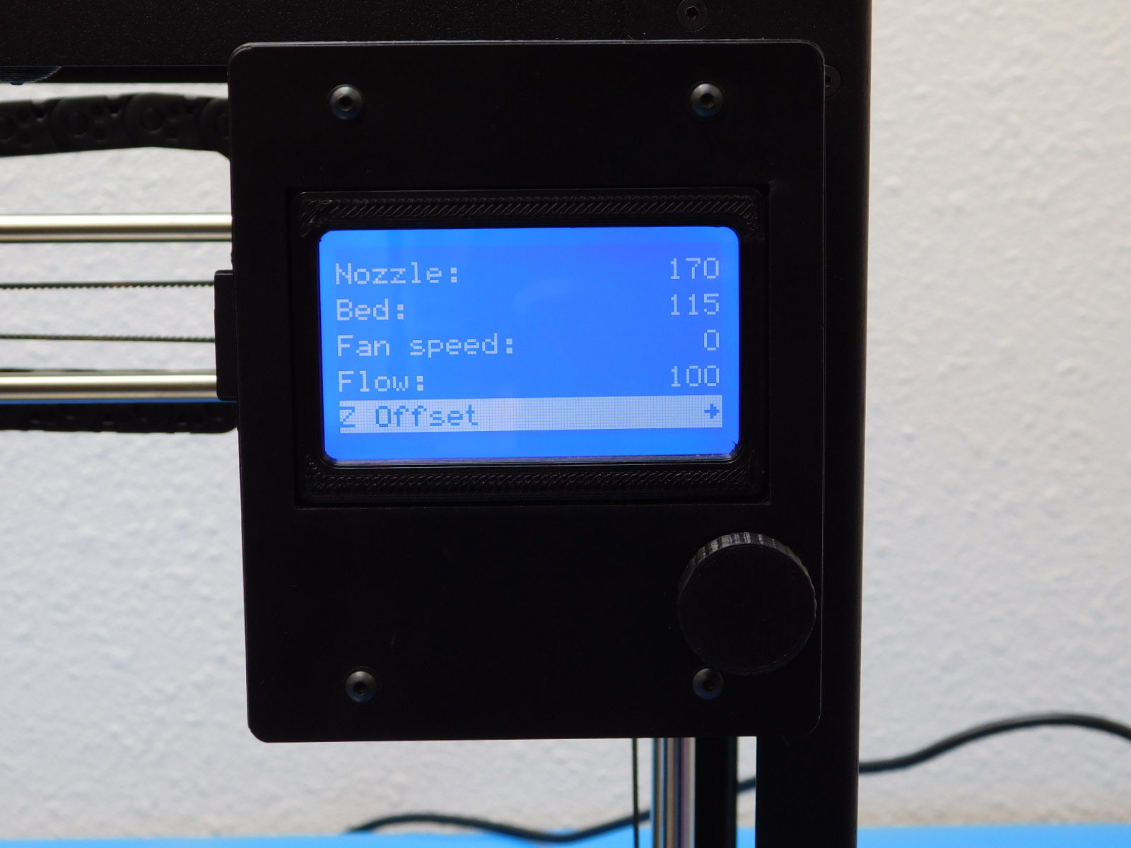
18B
Select Z Offset
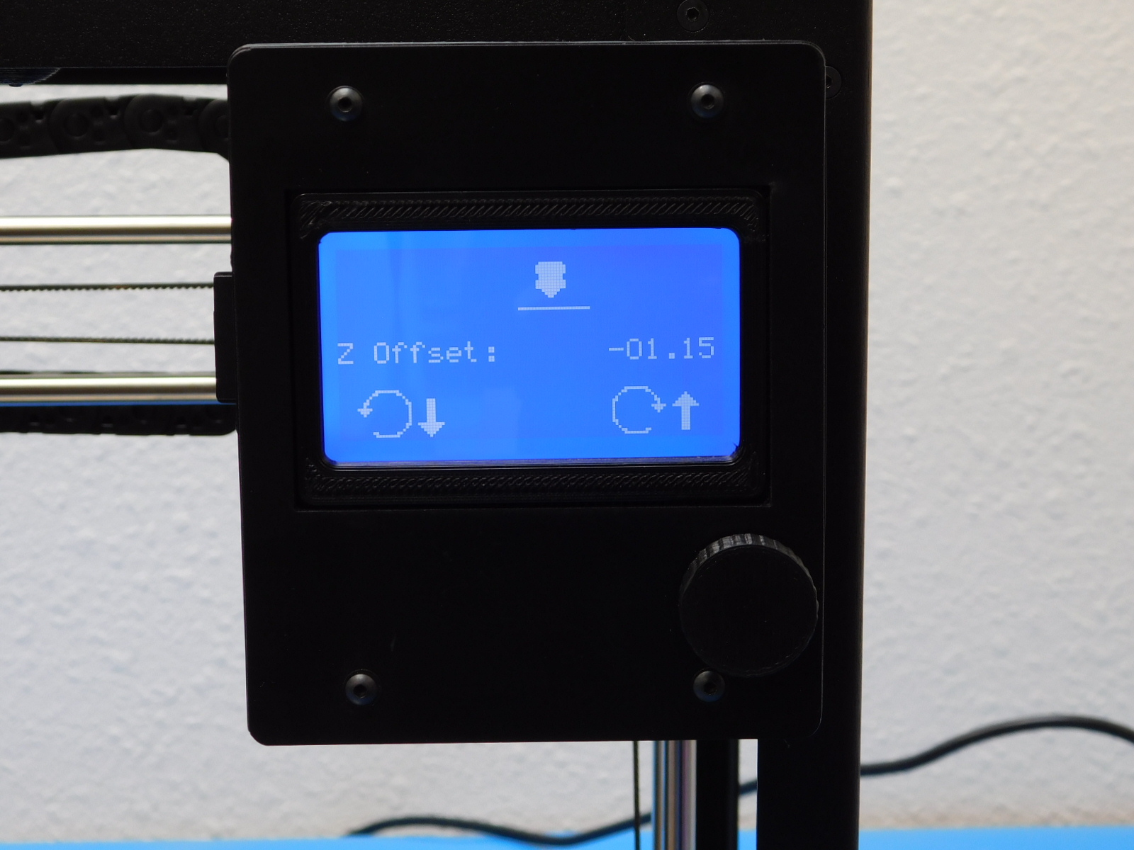
18C
Rotate the knob counterclockwise to bring the hot end nozzle closer to the print surface. Rotate the knob clockwise to move the hot end nozzle farther away from the print surface.
18D
Note the Z-offset value once adjusted. Follow the instructions at LulzBot.com/z-offset to store your ideal Z-offset.