Open HardwareAssembly Instructions
Guides for installation and assembly of the LulzBot line of products made by FAME 3D LLC.
Guides for installation and assembly of the LulzBot line of products made by FAME 3D LLC.
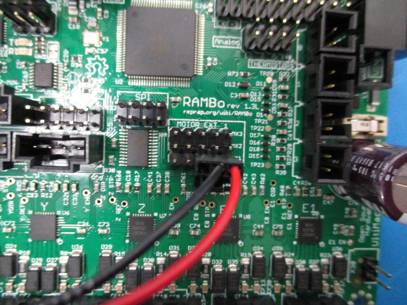
Locate the connector on the jumper that has the red wire in position 3 and the black wire in position 2. Connect the jumper to the bottom right of the MOTOR EXT 1 Pin header. Ensure the connector clip is facing away from the MOTOR EXT 1 print.
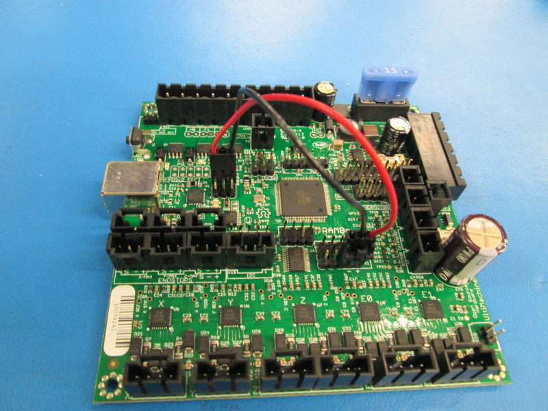
Connect the other end of the jumper into the 6 pin- pin header located behind the USBB port. Ensure the red wire is on the left side of the pin header and the black wire is on the right side of the Pin header.
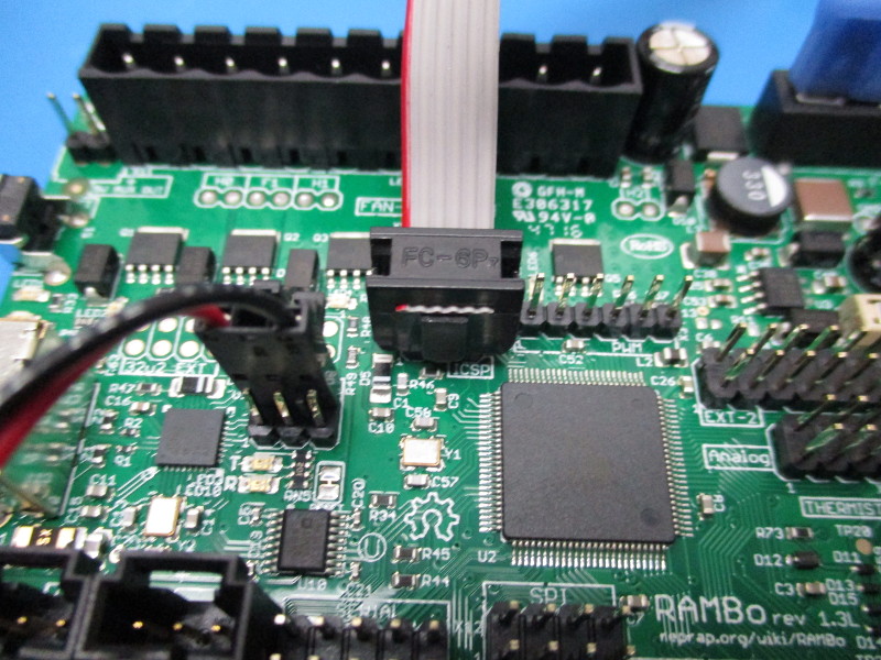
Connect the ICSP into the pin header labeled “ICSP”. Ensure proper orientation. ( see image- “ICSP connected”)
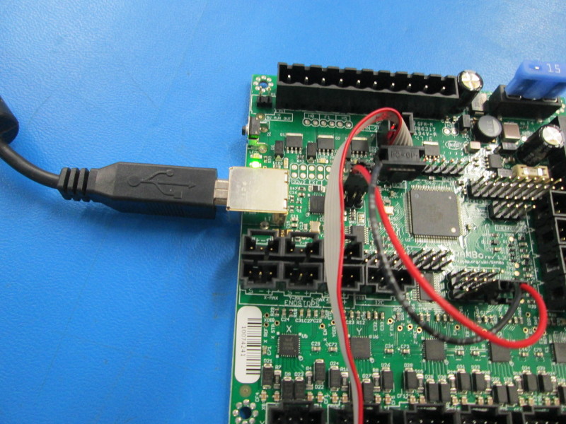
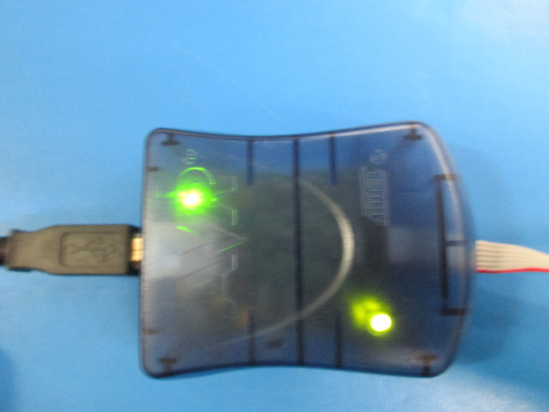
Connect the USBB into the USBB port on the RMBo Connect the second USBB into the USBB port on the ICSP Ensure the green lights are on
Open the computers terminal
Enter:
cd shared-j/devel/lulzbot/electronics/bootloader/bootloader-scripts/
to get to the directory
Enter:
./rambobootloaders.sh
and run the shellscript.
A successful flash will display-
    avrdude: verifying ...
    avrdude: 1 bytes of lock verified

    avrdude: safemode: lfuse reads as FF
    avrdude: safemode: hfuse reads as D0
    avrdude: safemode: efuse reads as FD
    avrdude: safemode: Fuses OK (E:FD, H:D0, L:FF)

    avrdude done.  Thank you.

    2560 Success!!
    Ctrl+C to quit any other key to program
After a successful flash, diconnect the usbb from the RMBo.
Disconnect the ICSP from the RMBo
Disconnect the jumper from the RMBo
Place the flashed RMBo into a new Static Shield bag
To flash another RMBo, repeat steps 1 and 2. To run the shellscript, press the spacebar.
If a successful flash repeat step 4