Open HardwareAssembly Instructions
Guides for installation and assembly of the LulzBot line of products made by FAME 3D LLC.
Guides for installation and assembly of the LulzBot line of products made by FAME 3D LLC.
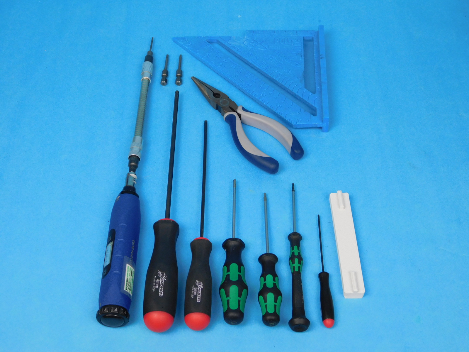
1x- [AS-PR0120] Control Box Assembly
1x- [AS-PR0125] Y-Axis Assembly
1x- [AS-PR0139] Quiver Frame Assembly
1x- [AS-PR0144] Filament Sensor Assembly
1x- [AS-PR0145] Quiver, X-Carriage Assembly
2x- [AS-PR0149] PTFE Feed Tube (Cut)
1x- [AS-TH0074] ServoDual Toolhead
1x- [PP-IS0100] X-Belt Clamp with Insert
1x- [PP-IS0101] Interface Board Cover with Insert
1x- [PP-IS0103] Y Chain to Bed Mount with Inserts
1x- [PP-GP0377] X bump stop
5x- [PP-GP0390] Cable Clip
1x- [PP-GP0405] Z endstop cable cover
2x- [PP-GP0426] Sensor Cable Cover
1x- [PP-GP0430] Tube collar 1
1x- [PP-GP0431] Tube collar 2
1x- [PC-BD0111] Dual_Interface Rev_ D PCBA

3x- [HD-BT0073] M5x10 BHCS
2x- [HD-BT0104] M3 x 8 Bolt, BHCS, SST
14x- [HD-BT0128] M3 x 6 Bolt, FHCS Black-Oxide
1x- [HD-BT0185] M3x16 SHCS
1x- [HD-BT0196] M5x25 SHCS
1x- [HD-BT0206] M3x25 FHCS
1x- [HD-BT0248] Stainless Steel SHCS M3x55
2x- [HD-BT0249] Stainless Steel SHCS M3x16
1x- [HD-BT0225] M5x10 Stainless BHCS
4x- [HD-BT0231] M5x14 Thumb Screw
2x- [HD-MS0058] Wire Tie, 8" Black
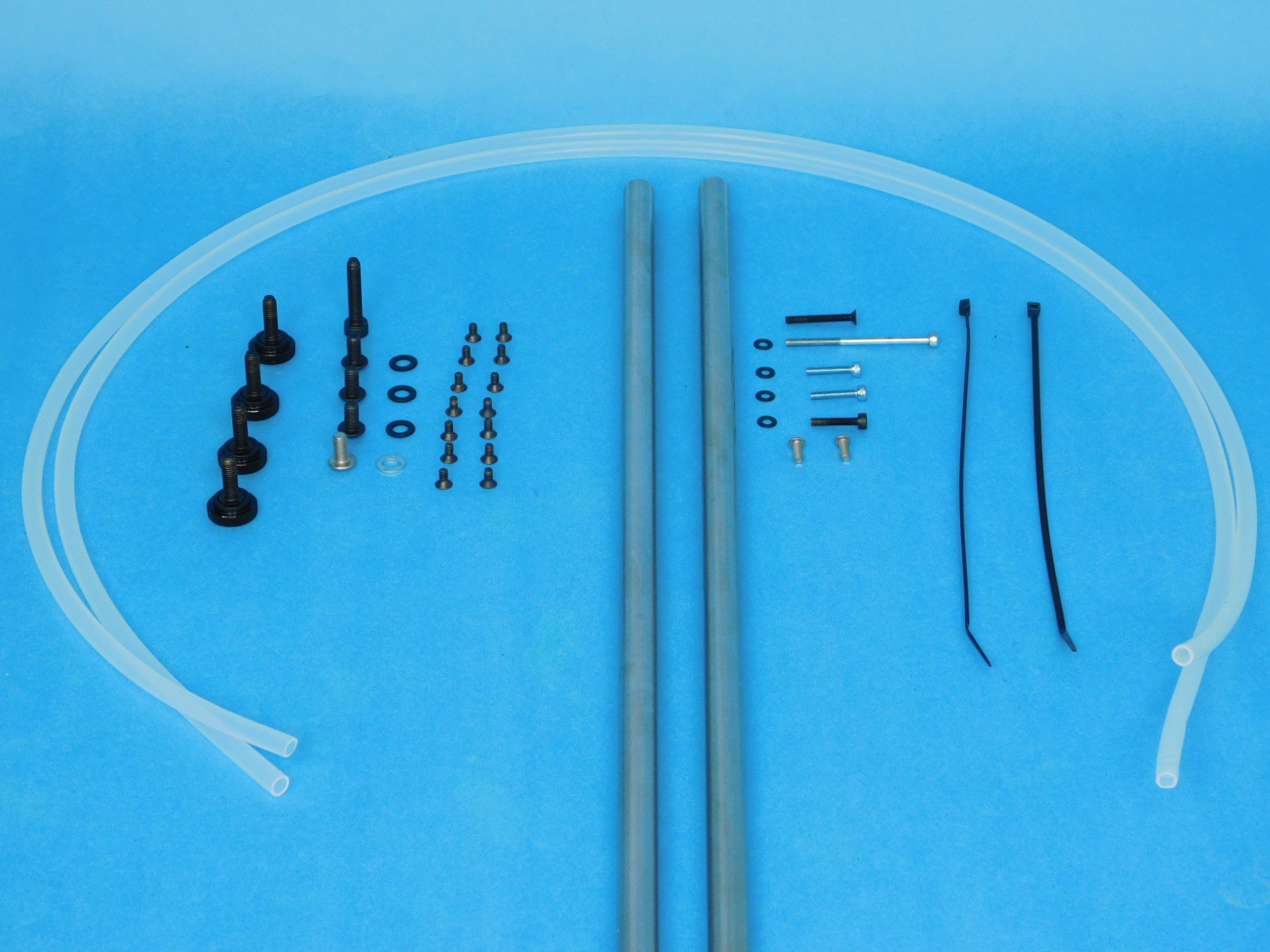
2x- [HD-RD0066] 12mm Smooth Rod, Stainless Steel, 540mm
1x- [HD-WA0007] M5 Washer, Steel, Zinc Plated
7x- [HD-WA0038] M3 Washer, Black-Oxide
3x- [HD-WA0040] M5 Washer, Black-Oxide
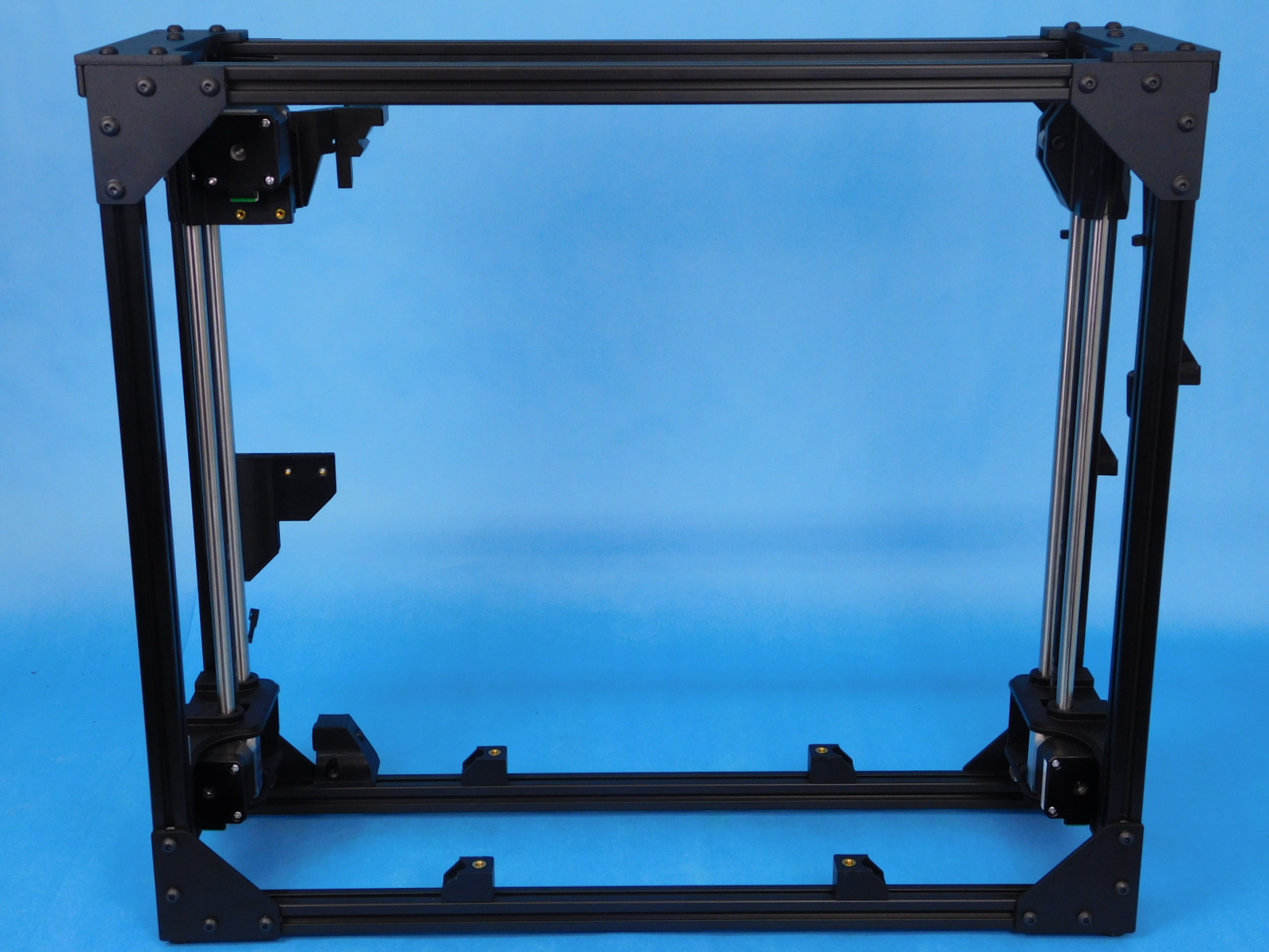
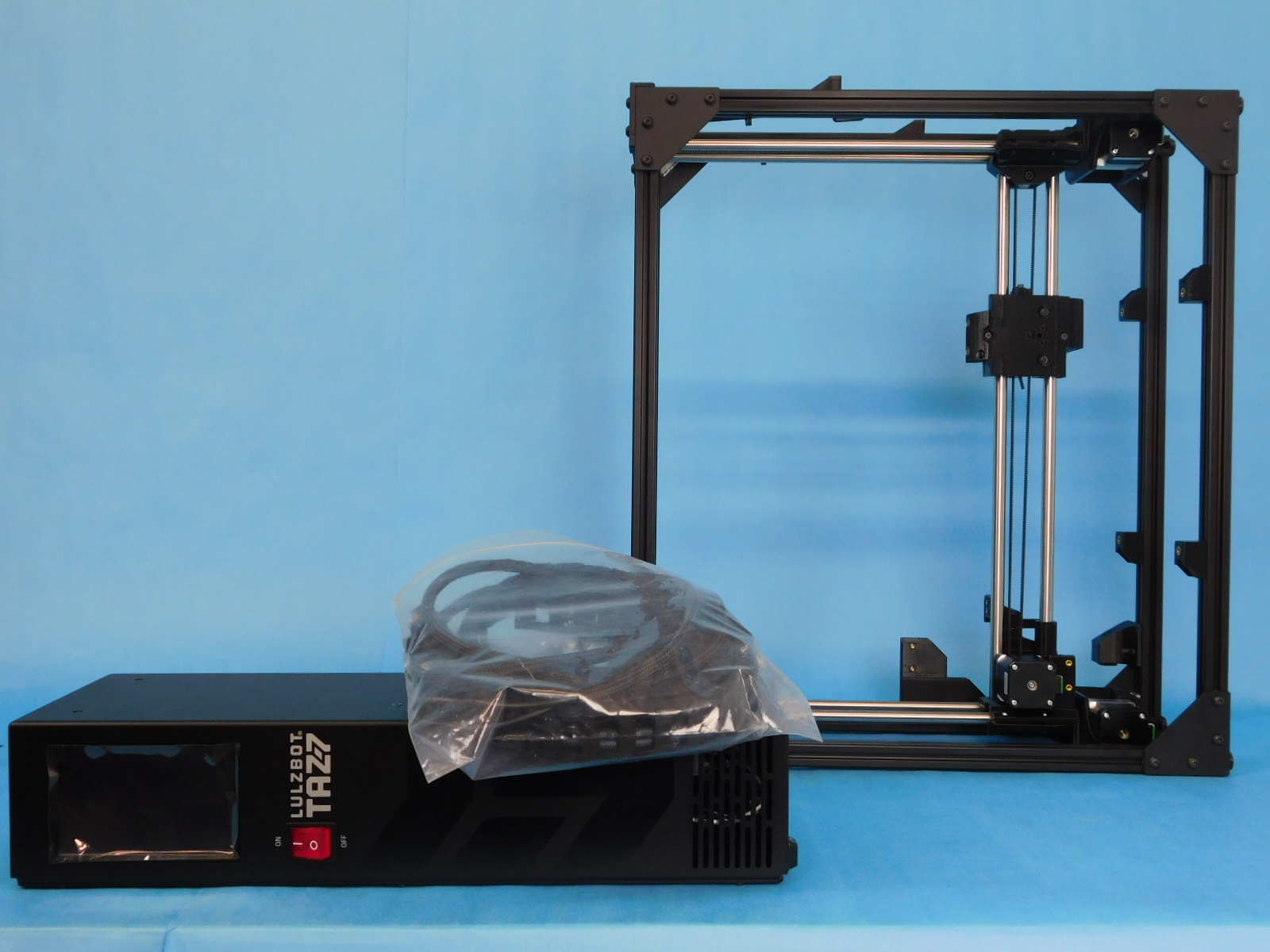
Obtain a completed Frame Assembly [AS-PR0139]
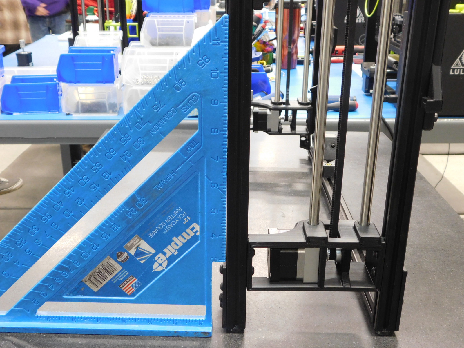
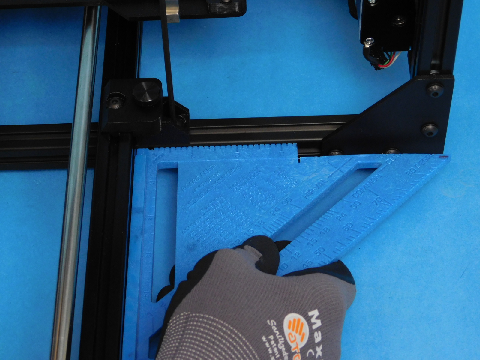
Place the completed frame on the granite block and verify that it sits flat and and doesn’t teeter, like a chair with one short leg.
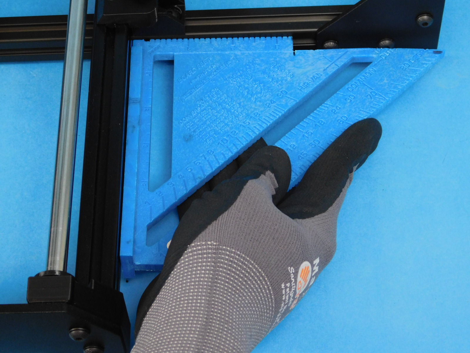
Line up the square along both ends, perpendicular to the length of the frame, as pictured.
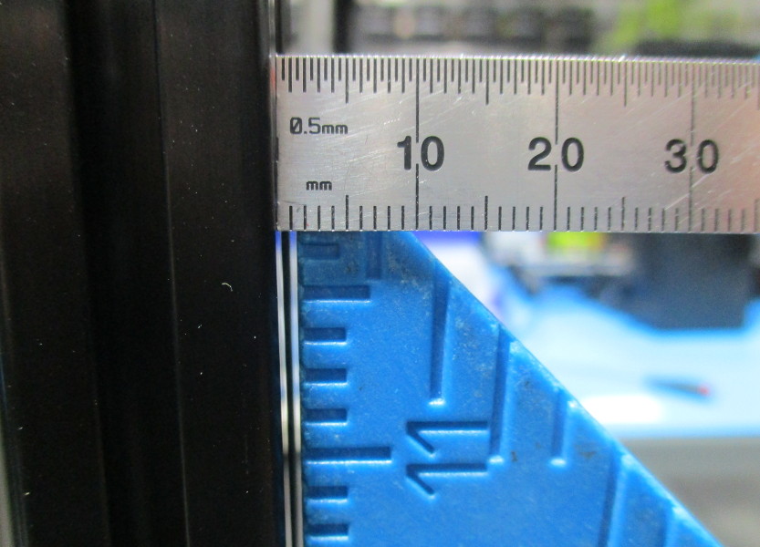
Examine the relationship between frame and square. If at any point the gap meets or exceeds 2mm, the frame must be rejected for re-squaring.
If the frame has passed inspection, place it on your workbench with the back of the machine facing you.

Wipe down the smooth rods to ensure they are free from any contaminants.
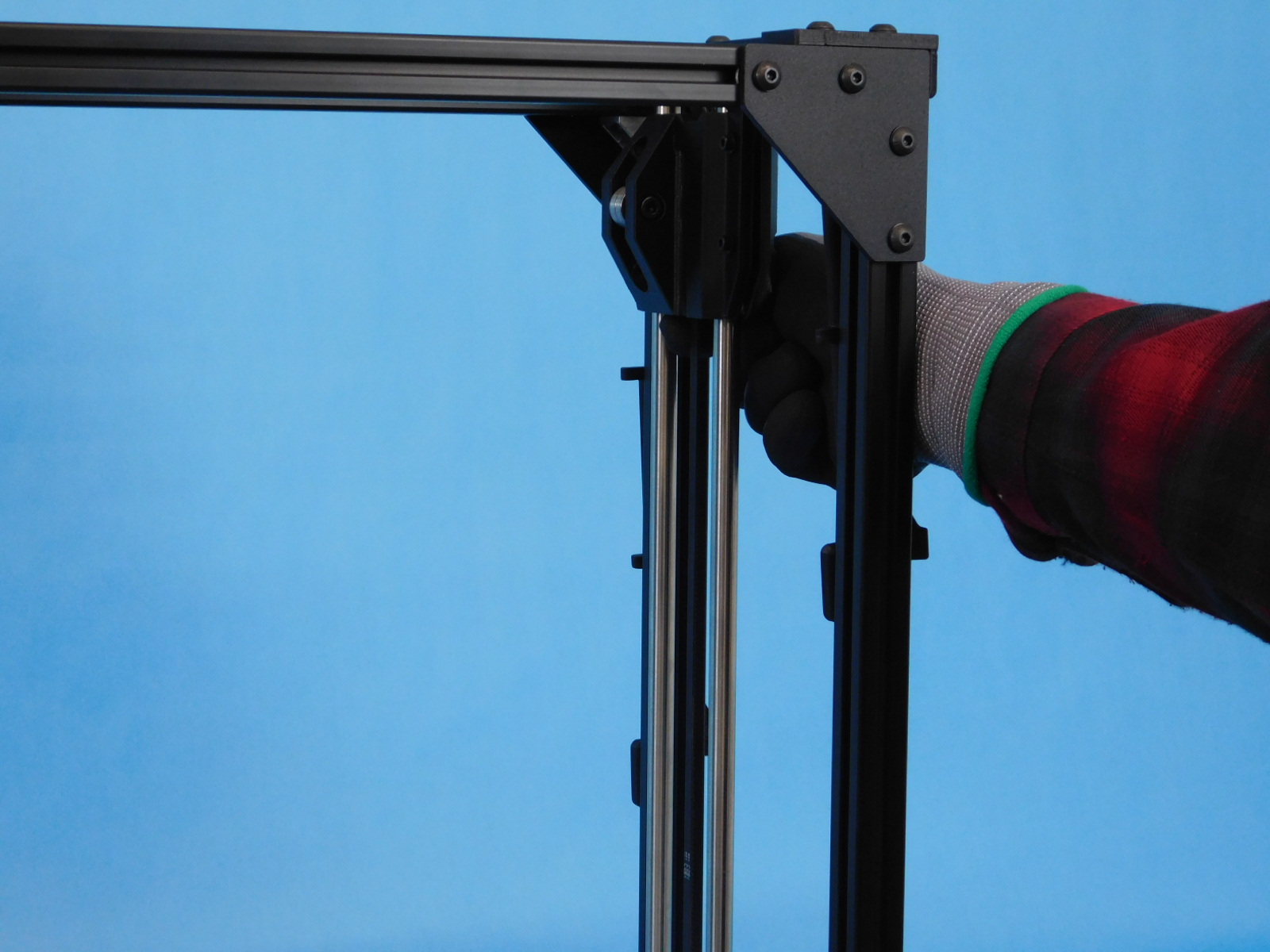
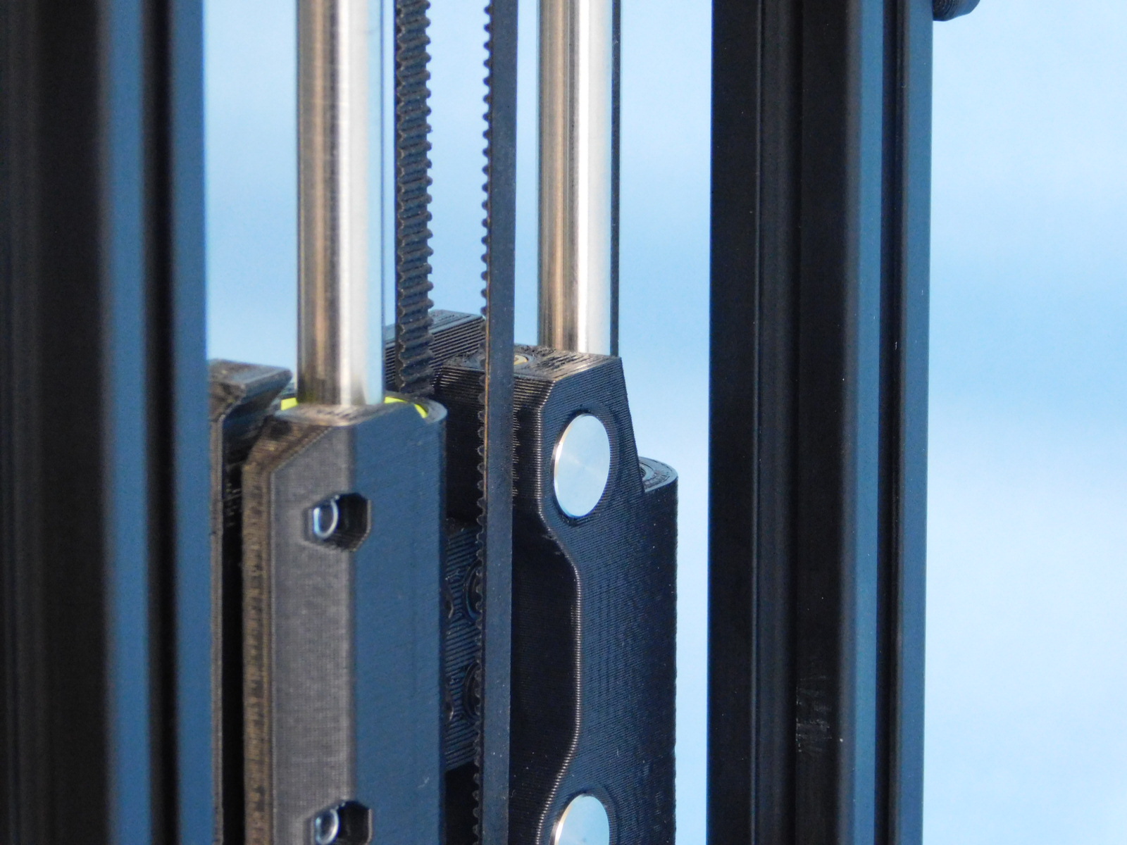
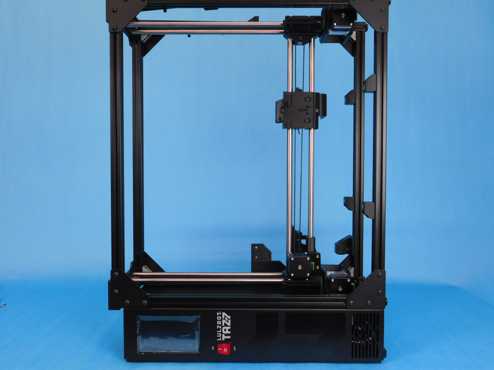
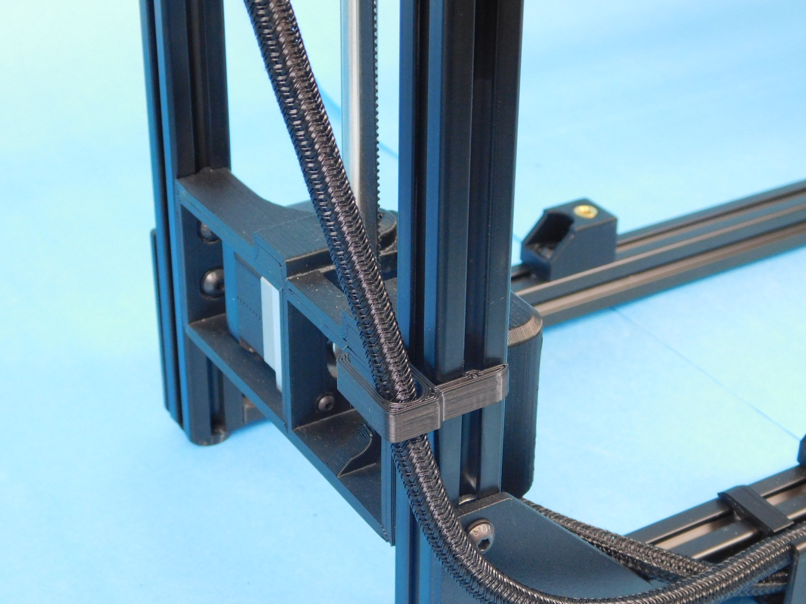
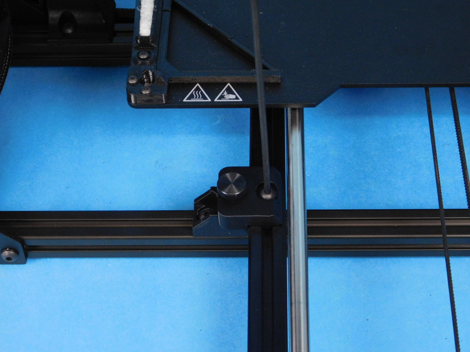
Move both sides of the Z-Axis (X-Ends) to the top of travel by grasping the printed part and pushing it upwards.
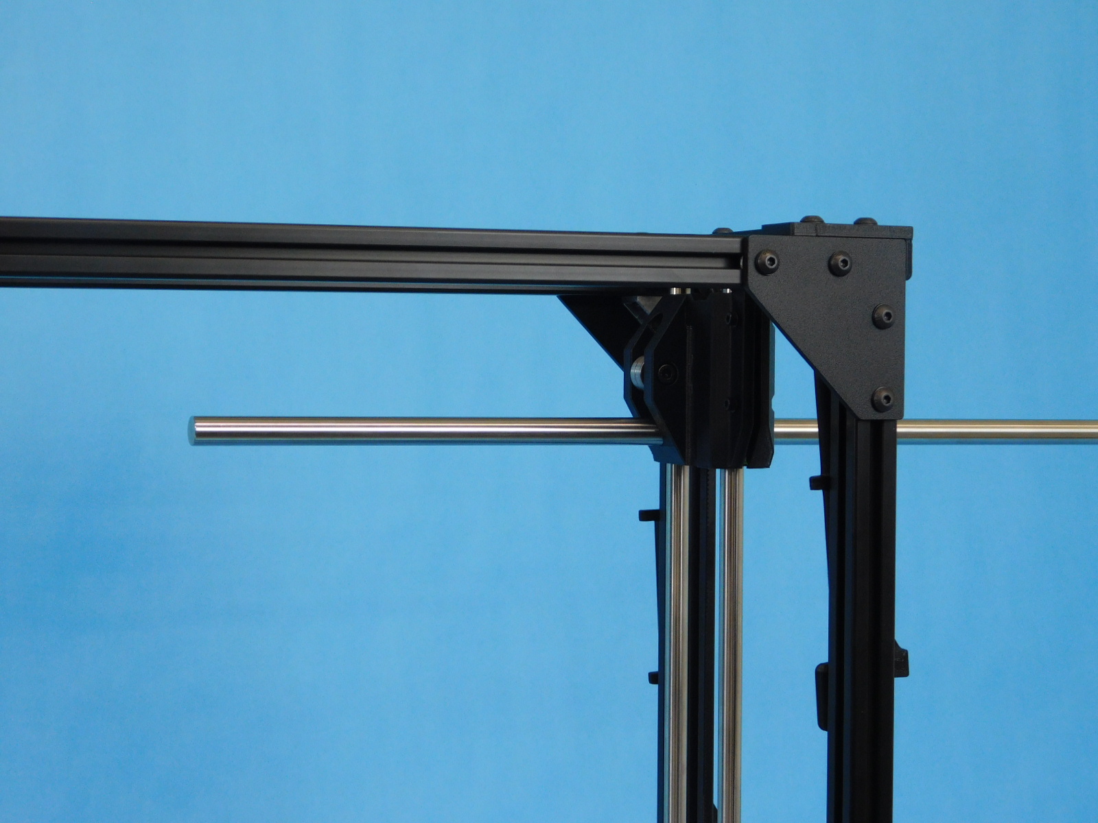
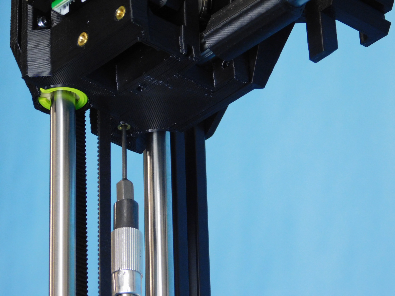
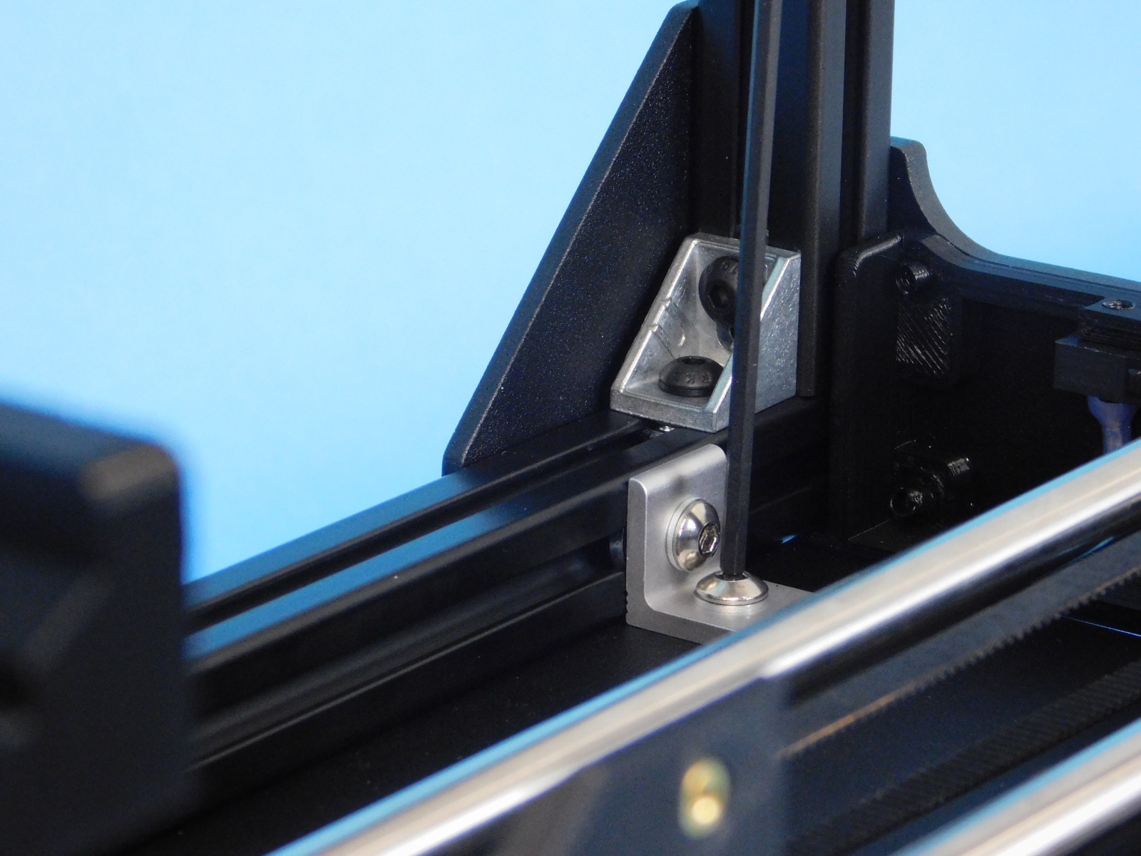
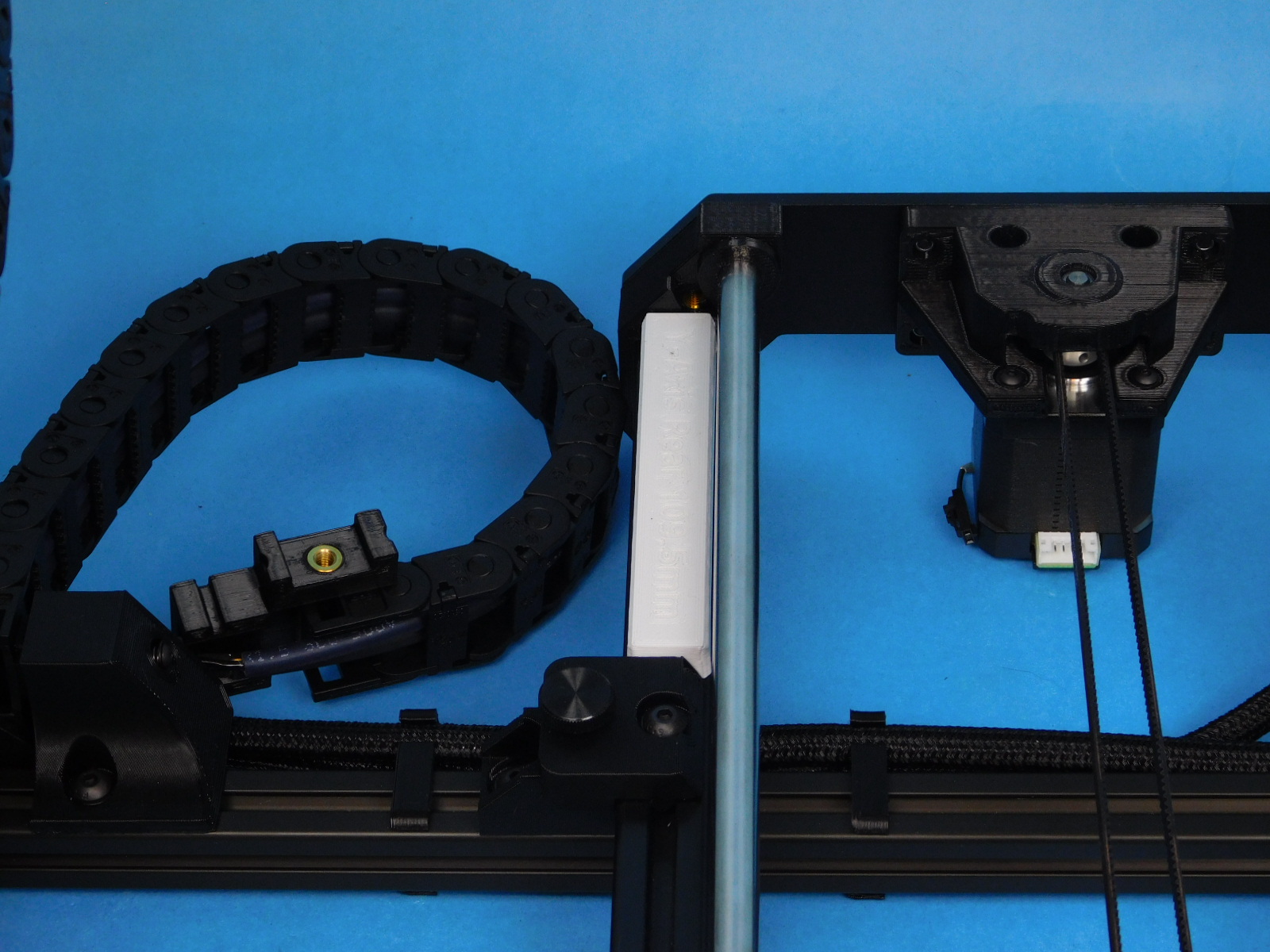
Obtain one 12mm Smooth Rod [HD-RD0066] and slide it through the lower 12mm hole of the X Idler End from the outside of the frame, stopping about half way.
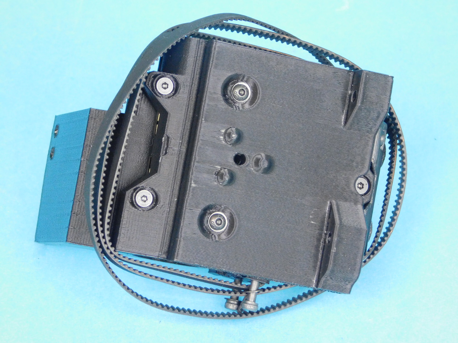
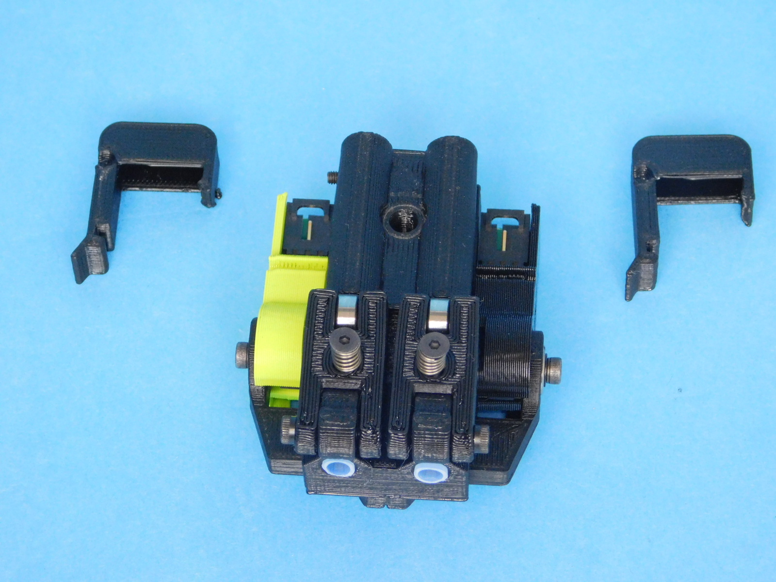
Place the double bearing side of the X Carriage Assembly [AS-PR0145] onto the smooth rod end inside the frame, oriented as pictured.
Install one X Bump Stop [PP-GP0377] onto the 12mm Smooth Rod end after the X Carriage Assembly.
Continue sliding the 12mm Smooth Rod [HD-RD0066] into the lower 12mm hole of the X Motor End until the end of the rod is flush with the outside of the X-Idler End (right side of frame).
Torque both lower smooth rod set screws (located on the underside of the X-Ends) to 3in*lbs.
Push the X-Bump stop into place against X-End Motor, ensure it mates flush with the printed part.


Push the axis to the middle of travel (mid-frame) by applying even downward force on the X-Ends.
Rotate the frame so the back is facing you.
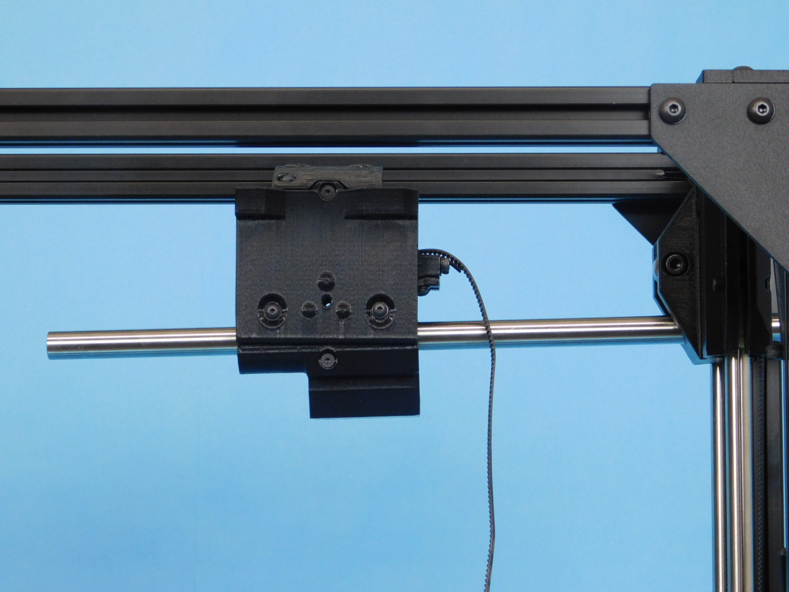
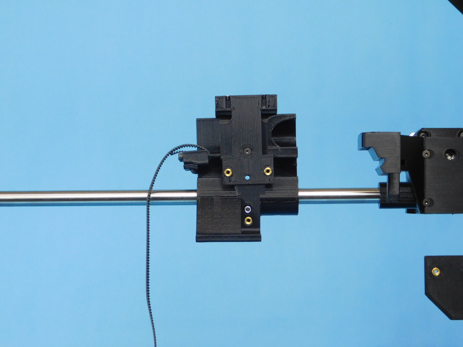
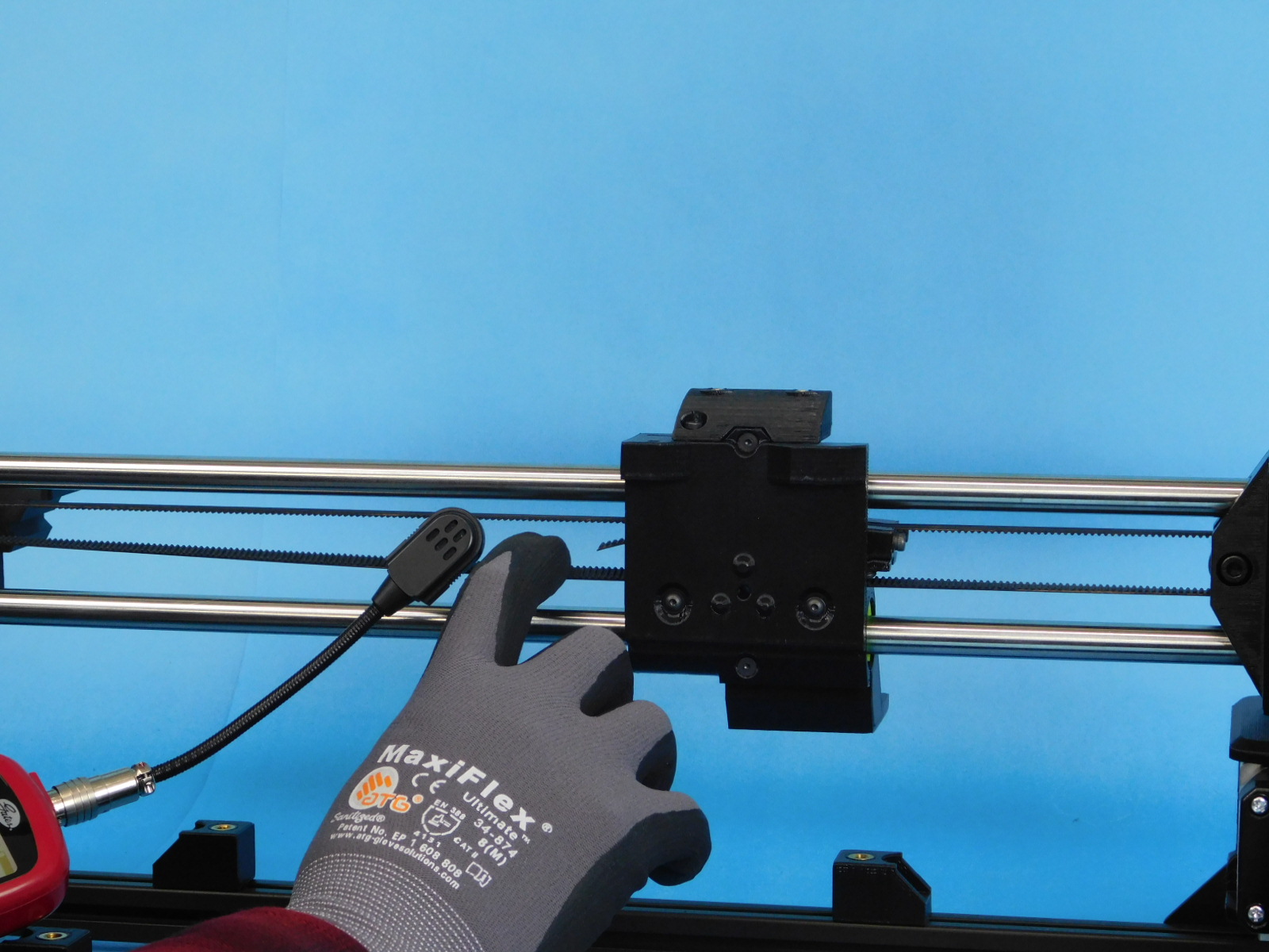
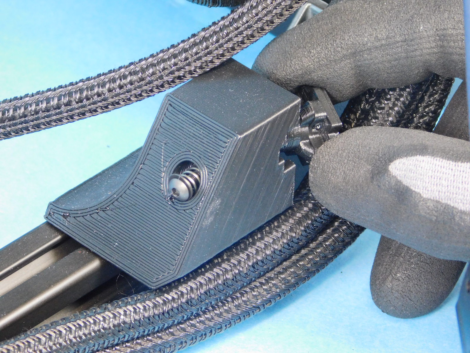
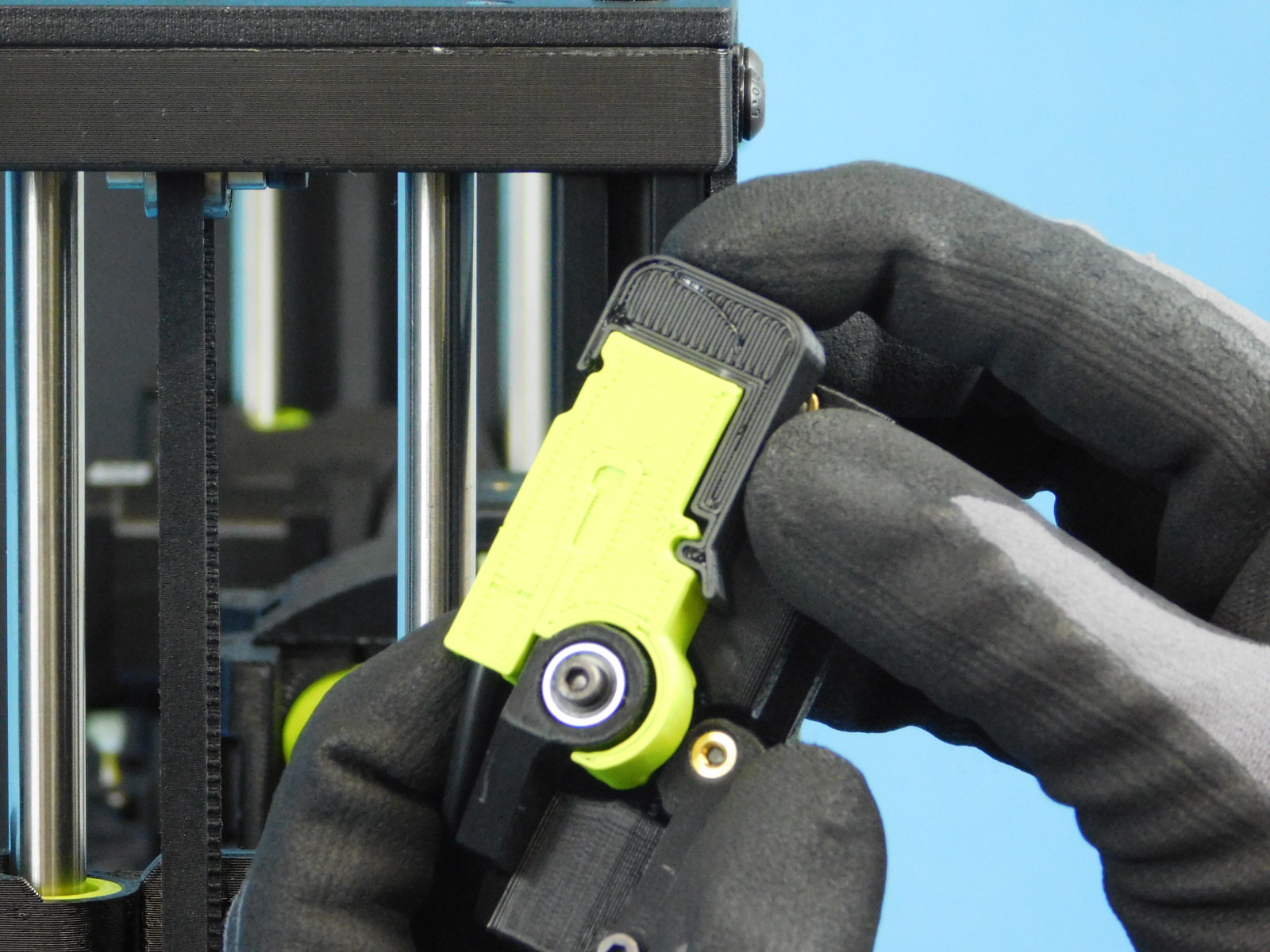
Orient the X Carriage Assembly [AS-PR0145] upright as pictured.
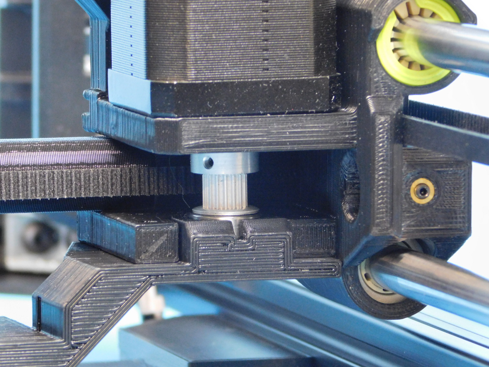
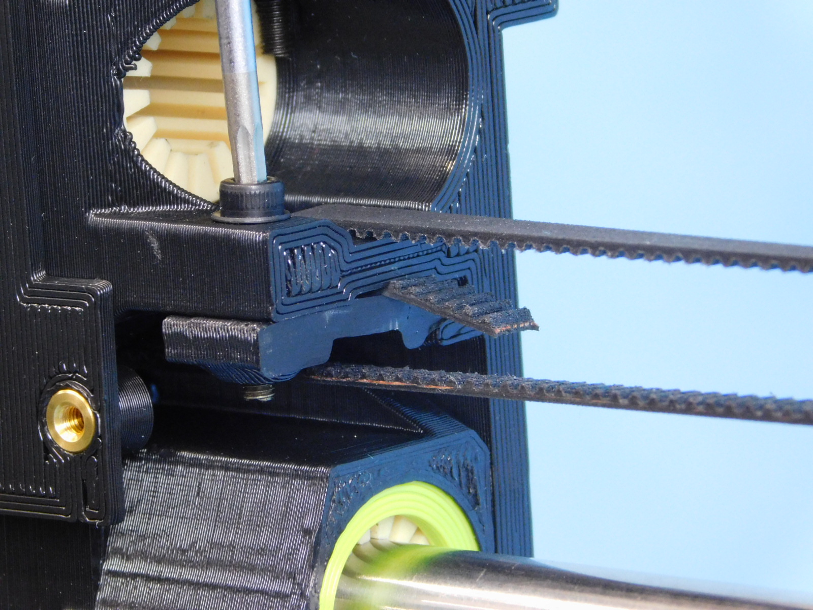
Straighten the X Axis drive belt attached to the X Carriage Assembly and route the end through the X-Idler End, beginning above the bearings with the teeth of the belt facing down.
Ensure there are no twists in the belt
Continue routing the X Axis drive belt back through the X-Carriage Assembly below the tensioner and behind the Interface Board Mount.
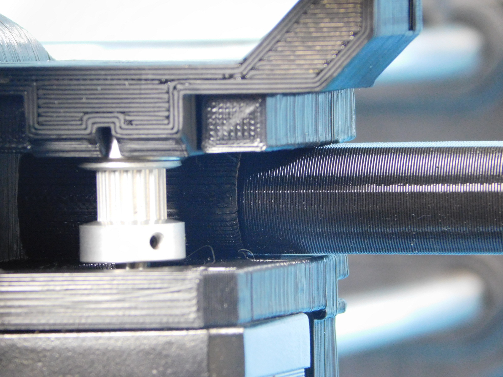
Route the drive belt around the X Motor pulley, beginning from below the pulley with teeth facing up.
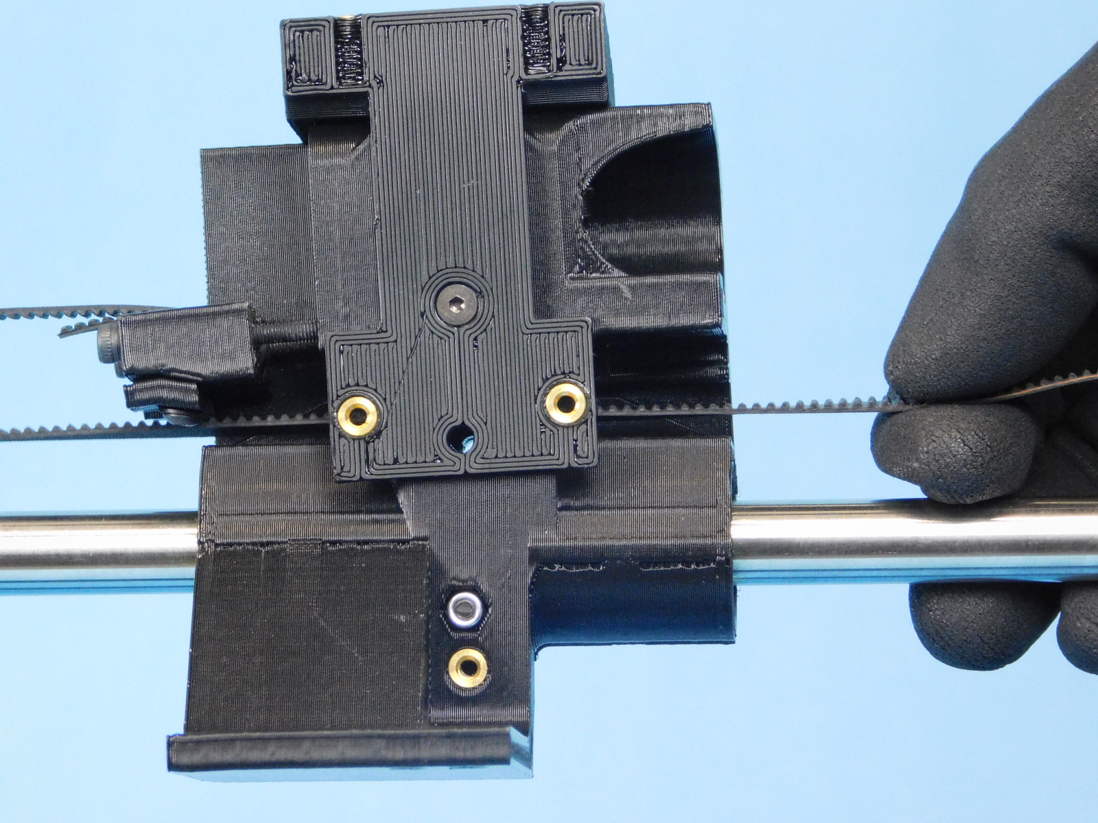
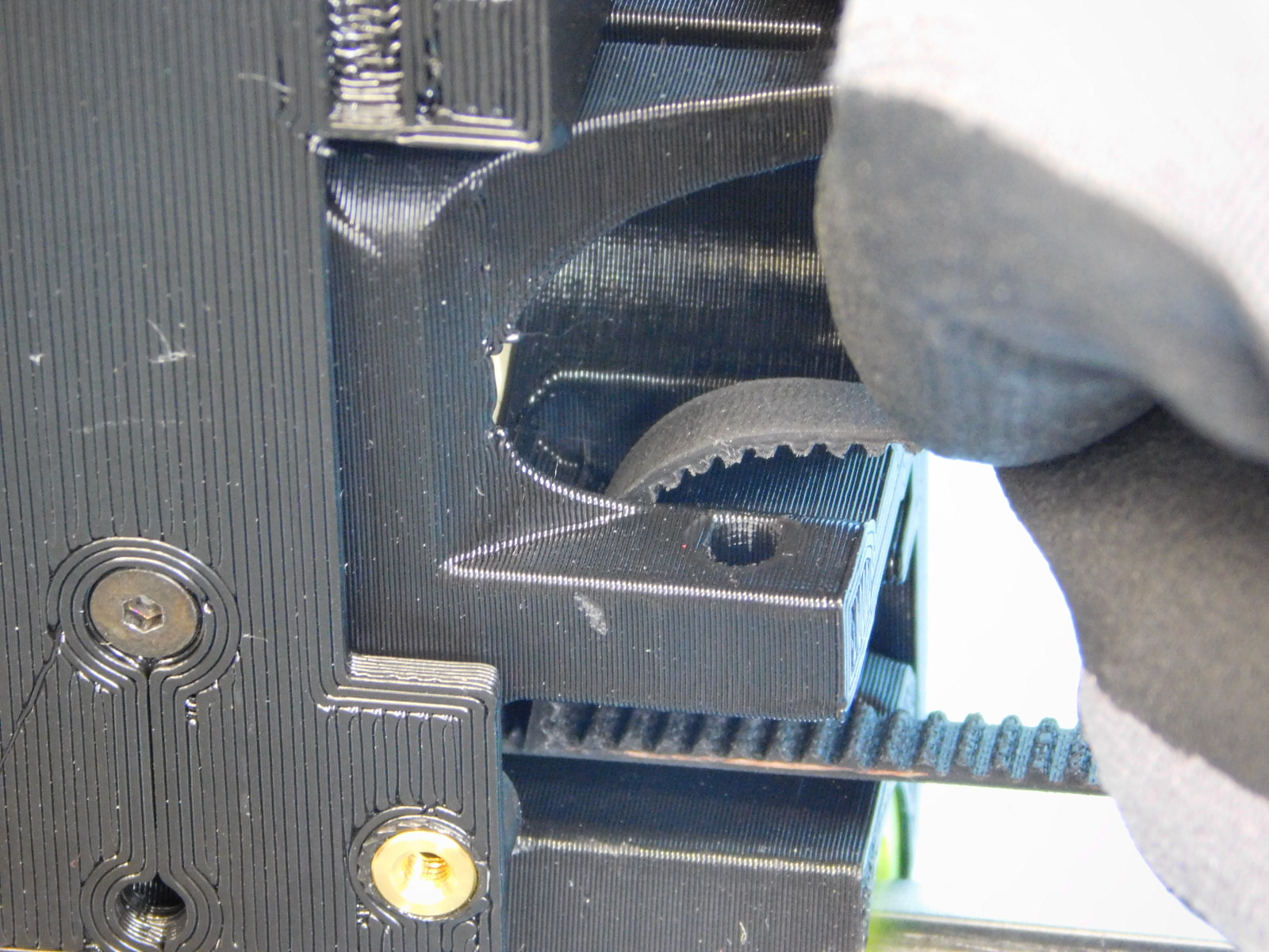
Route the belt through the clamp feature of the X-Carriage as pictured.
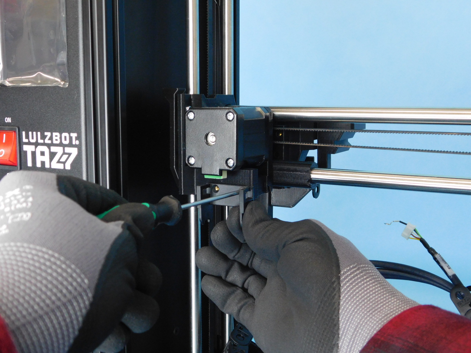
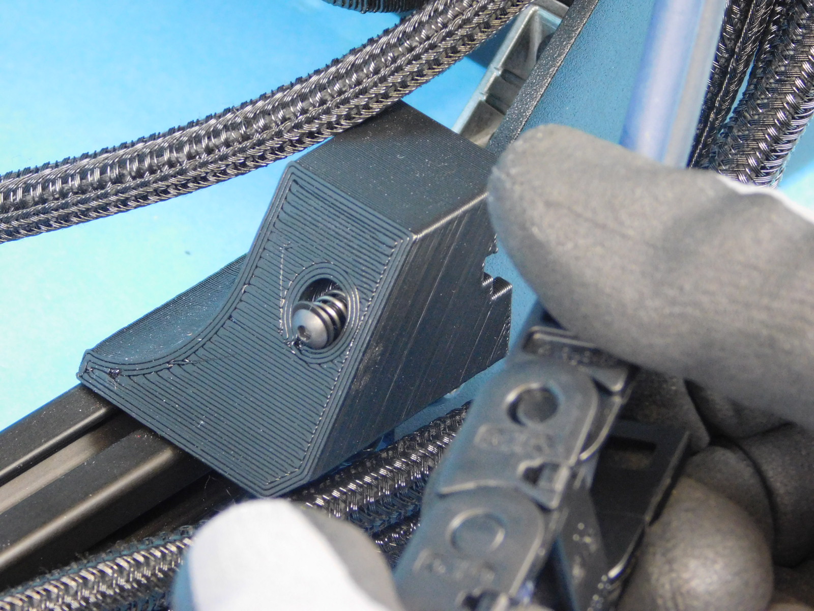
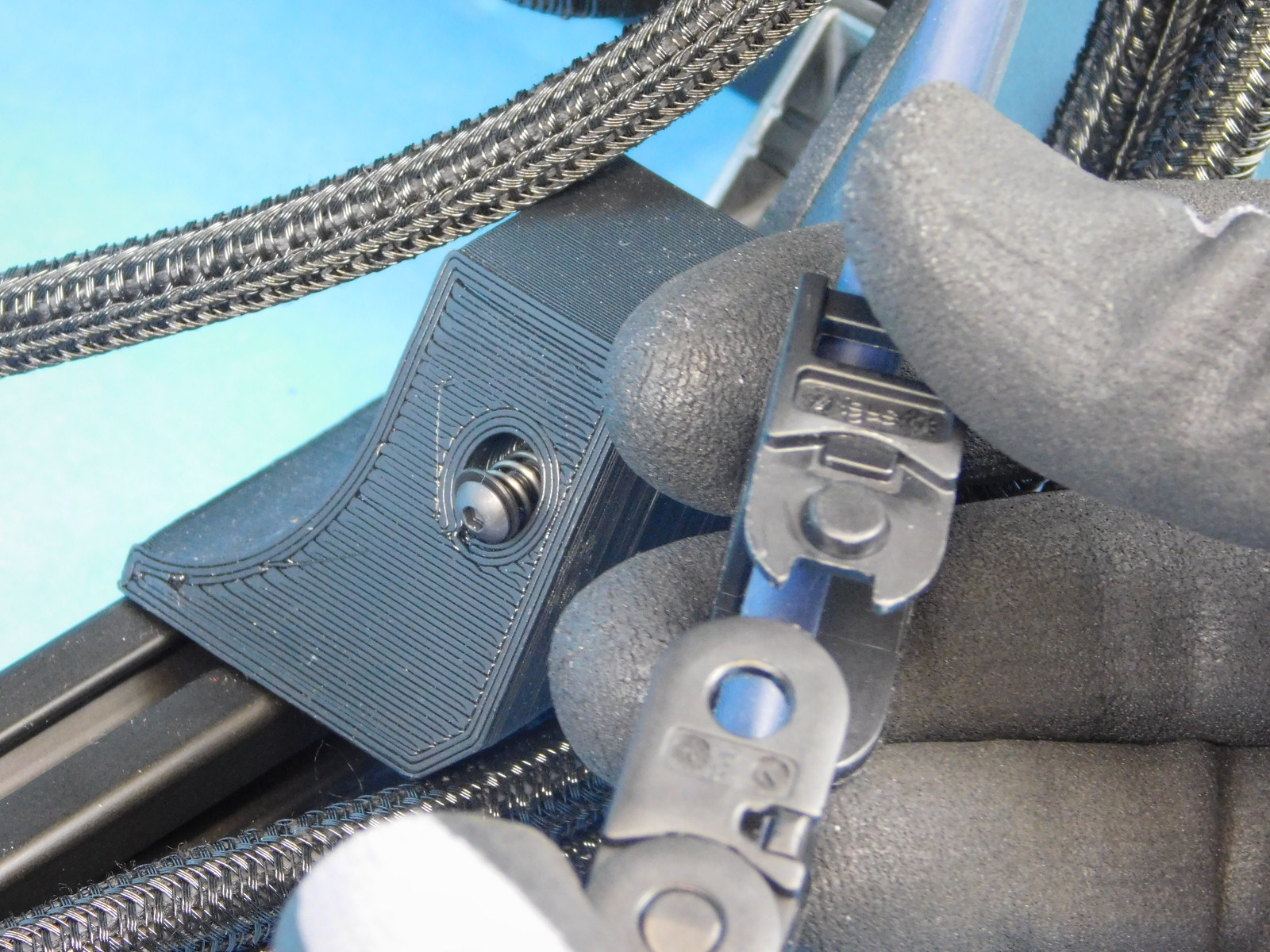
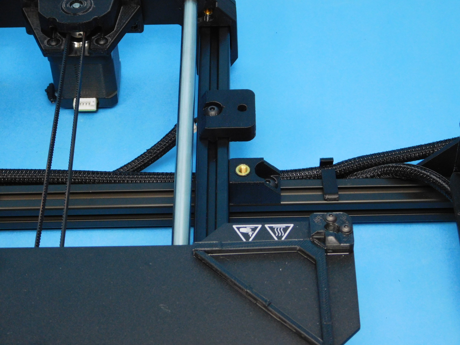
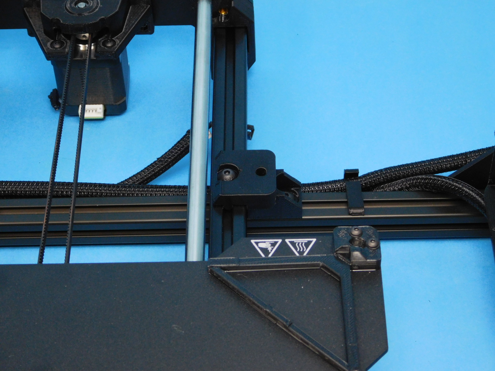
Place one X Belt Clamp w/ Insert [PP-IS0100] into the feature as pictured and thread one M3x16 SHCS [HD-BT0185] with washer [HD-WA0038] into the insert from above.
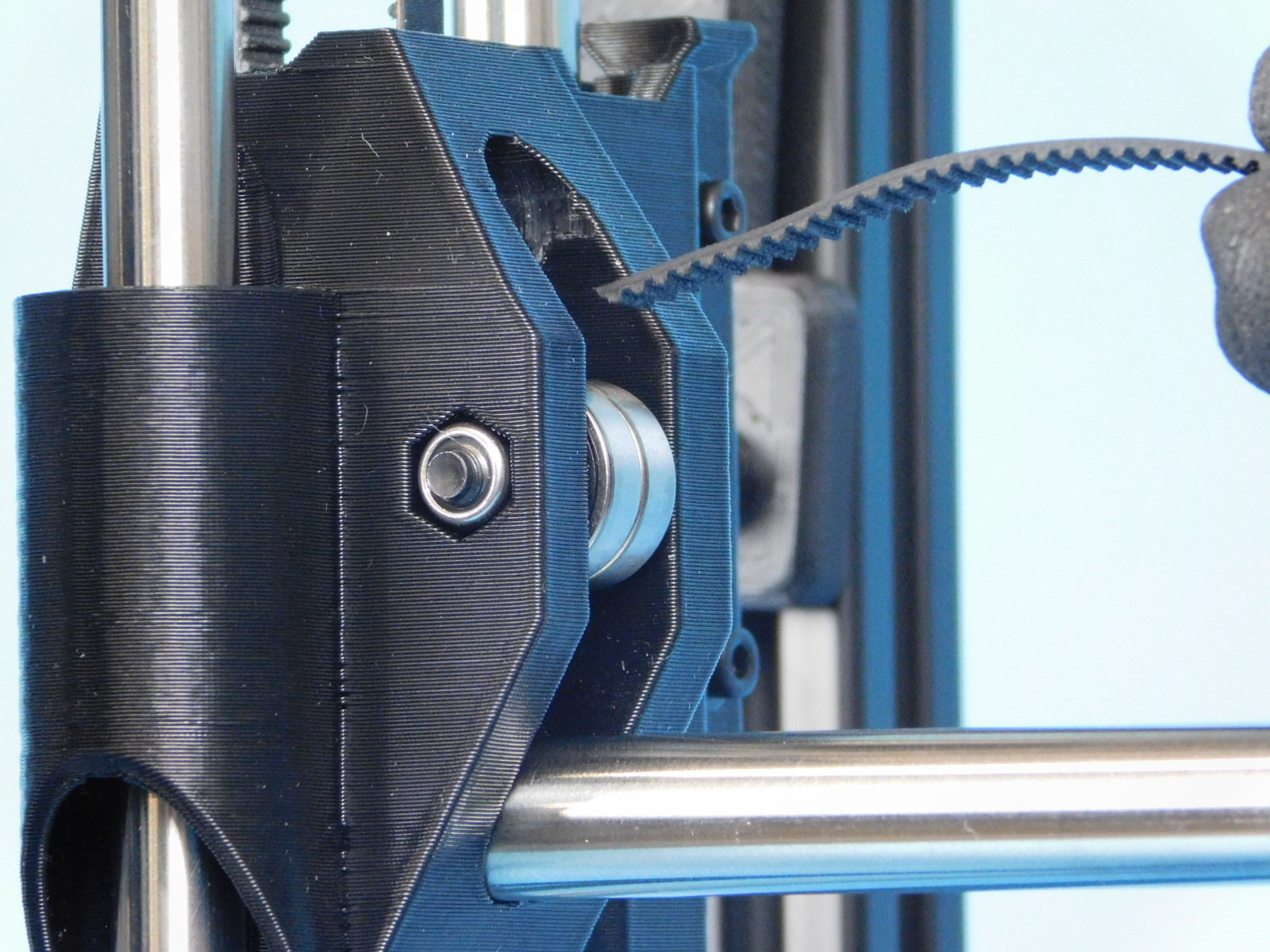
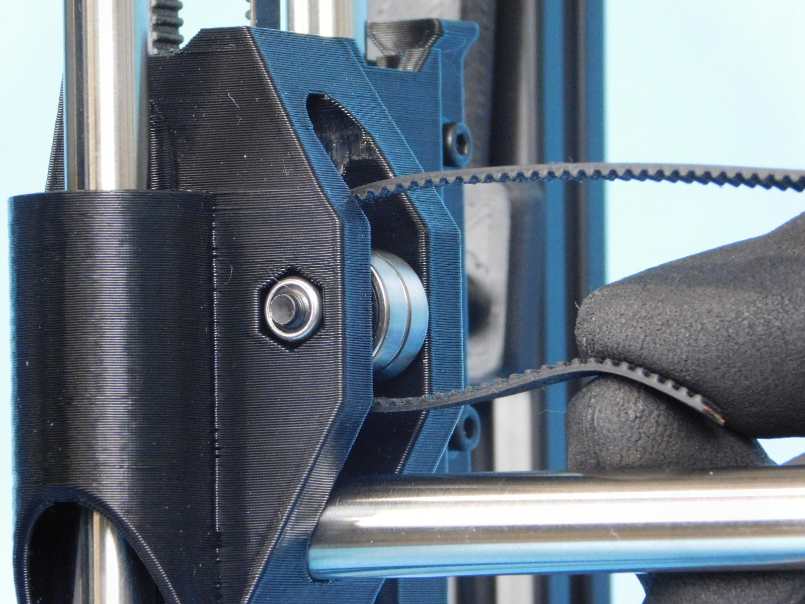
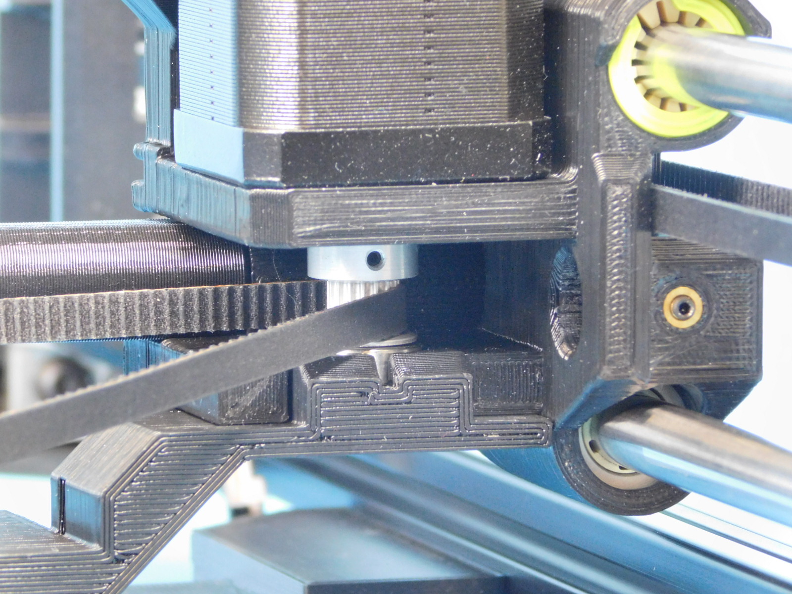
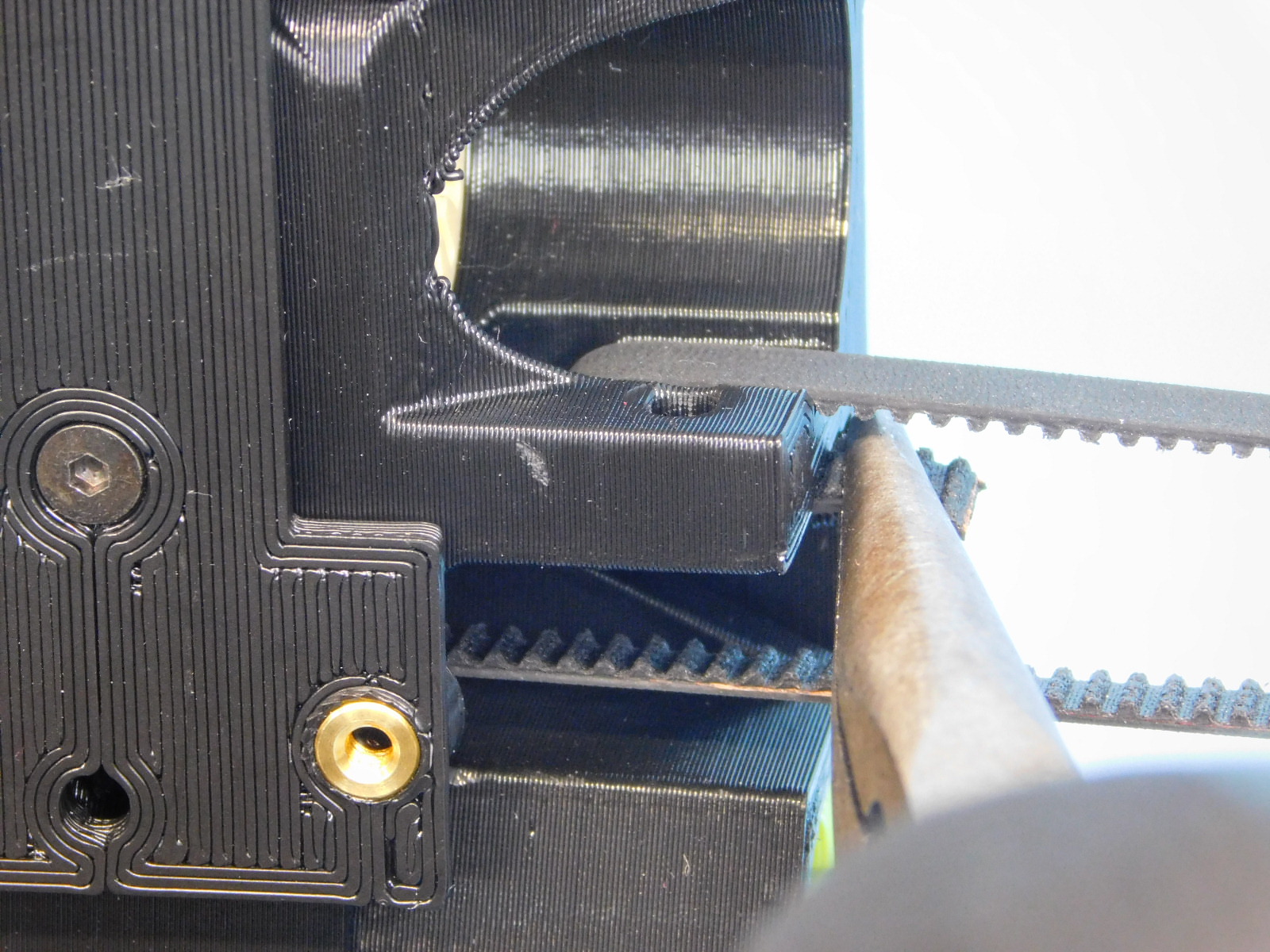
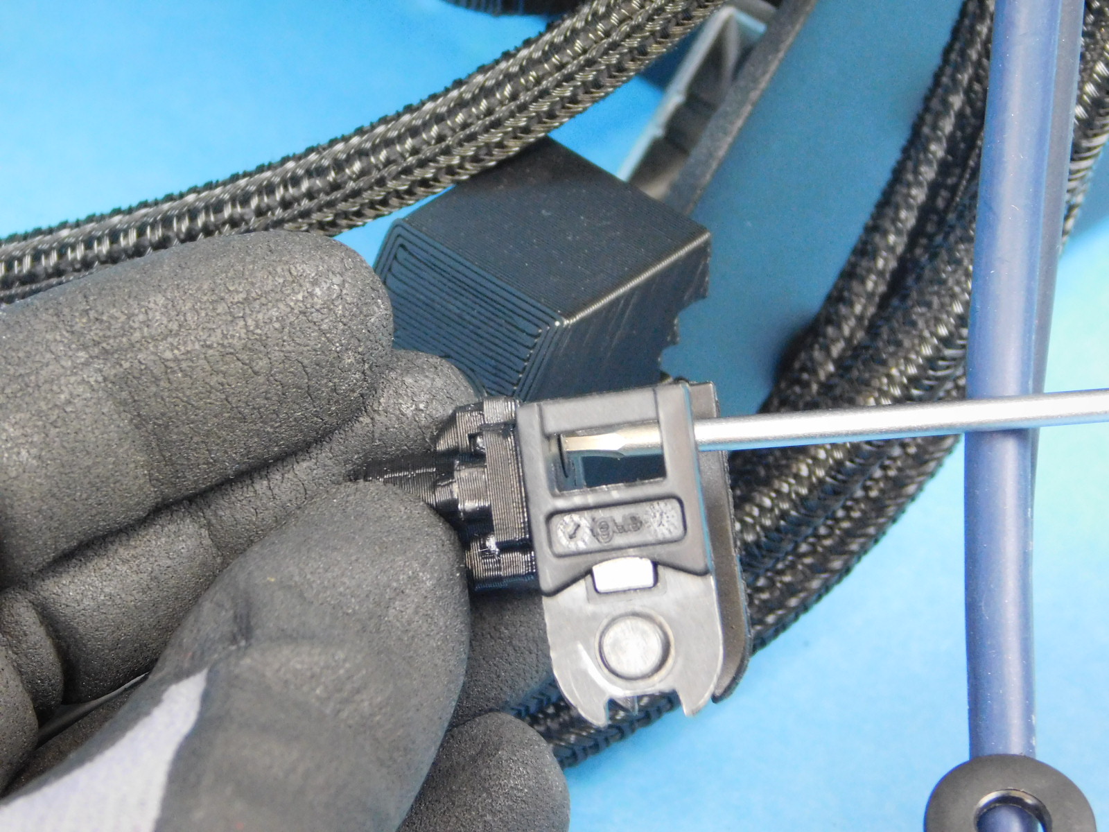
Using a pair of pliers, remove slack from the drive belt by pulling on the end.
Do not tension the belt at this point, only remove the slack
Torque the X-Belt Clamp fastener to 5in*lbs

Wipe down the smooth rods to ensure they are free from any contaminants.
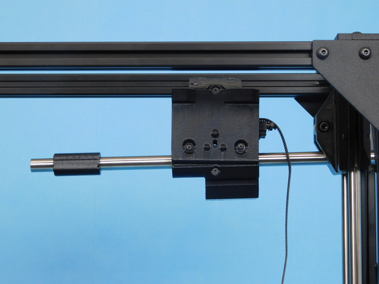
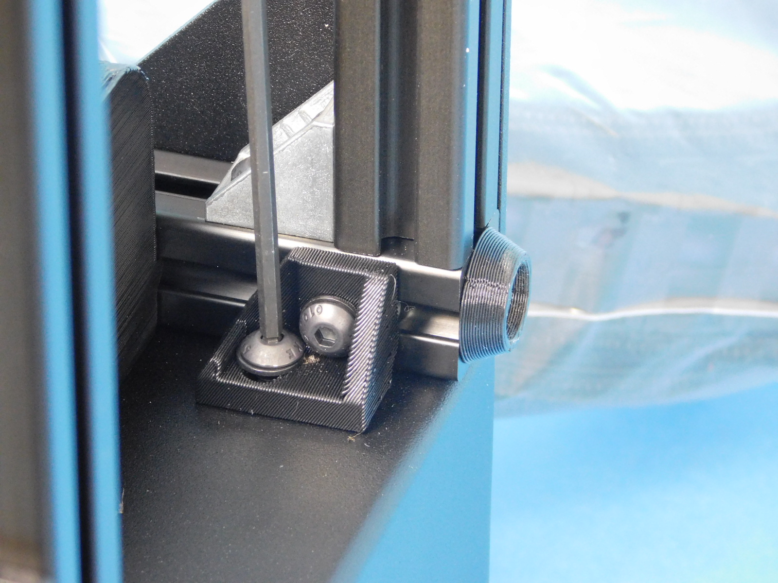
Push the axis to the bottom of travel so that both ends rest upon the Z-Lowers.
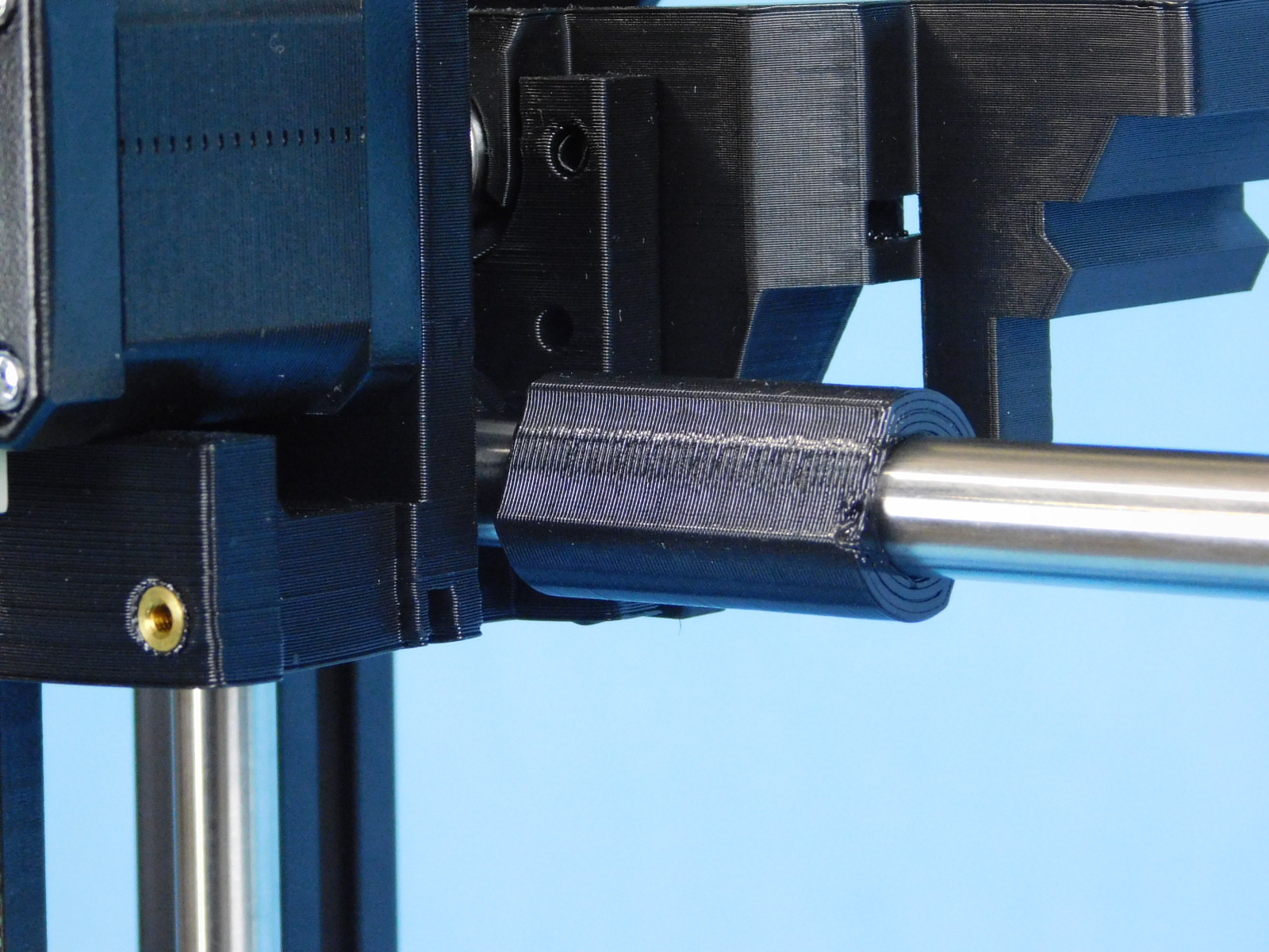
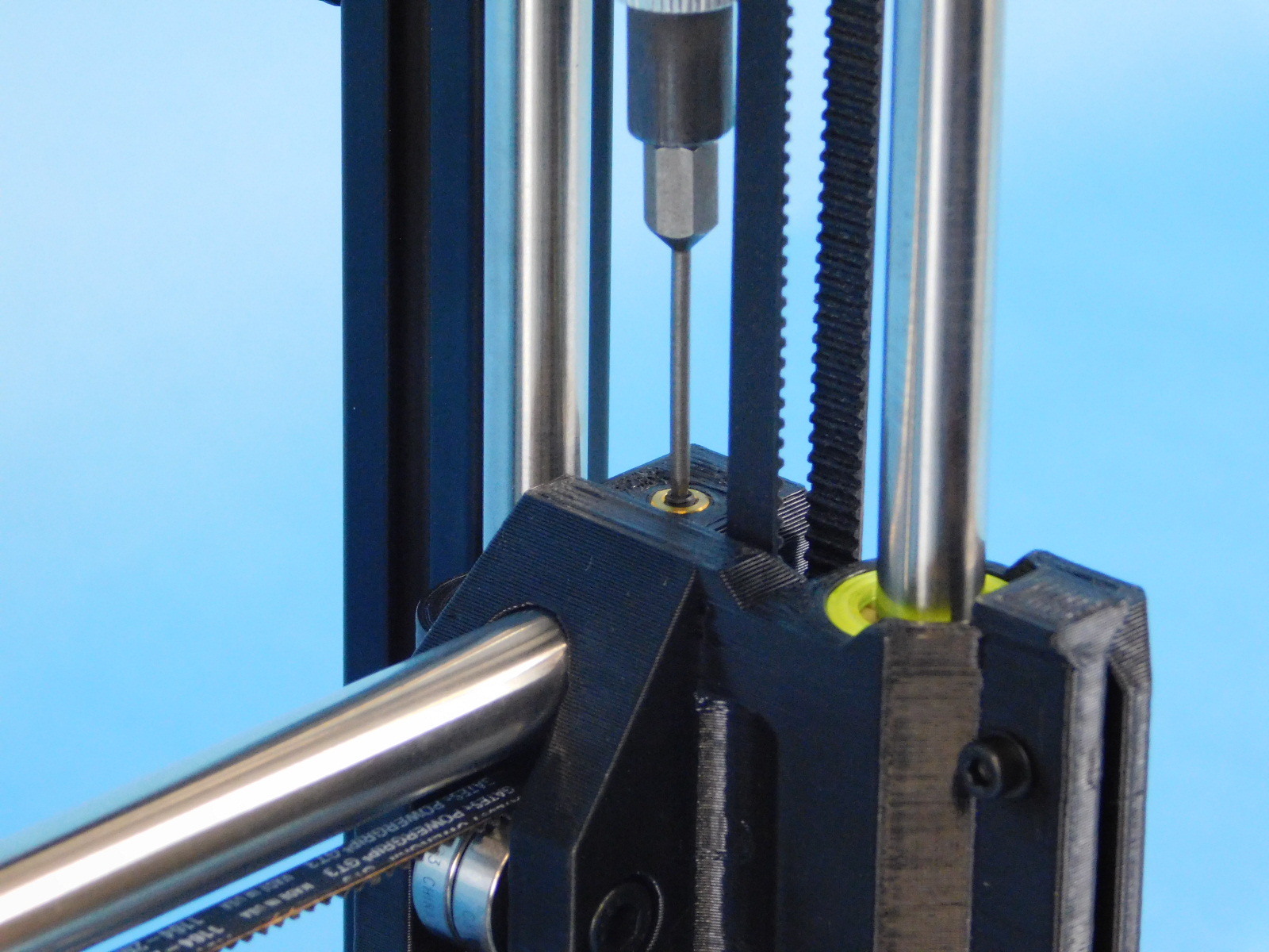
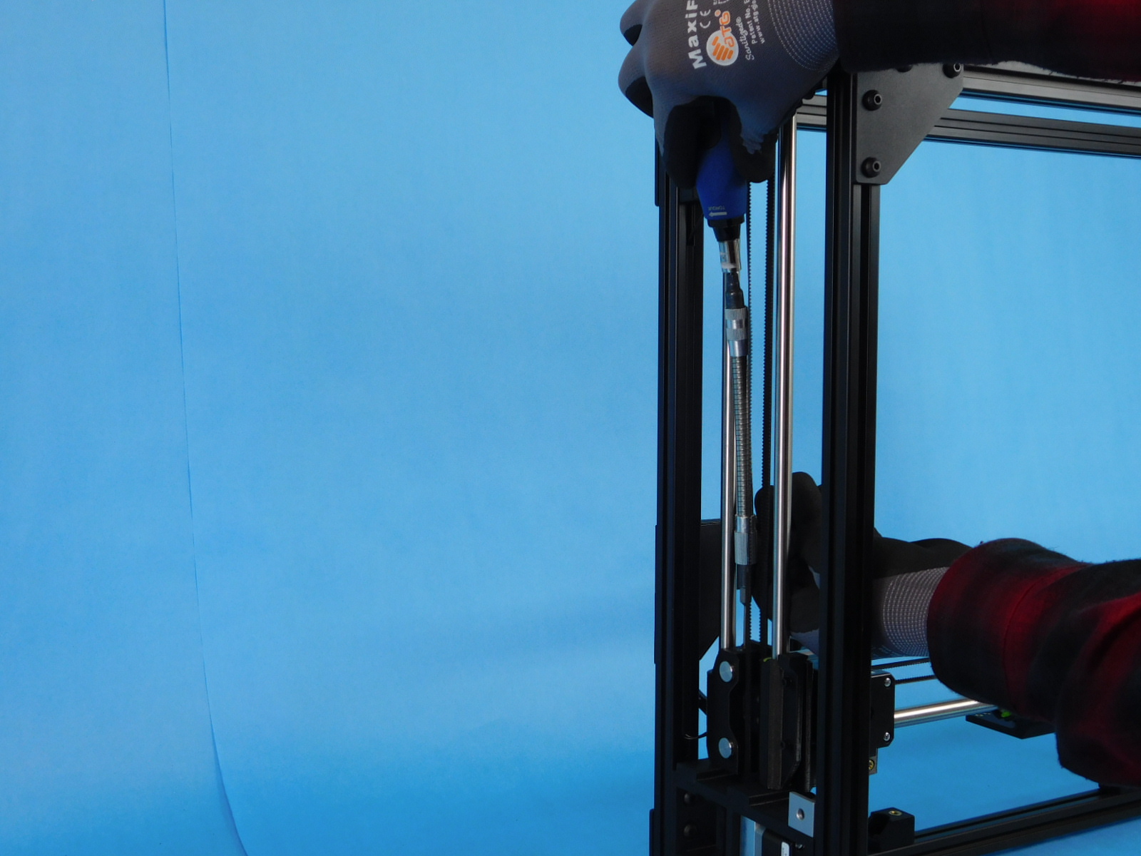
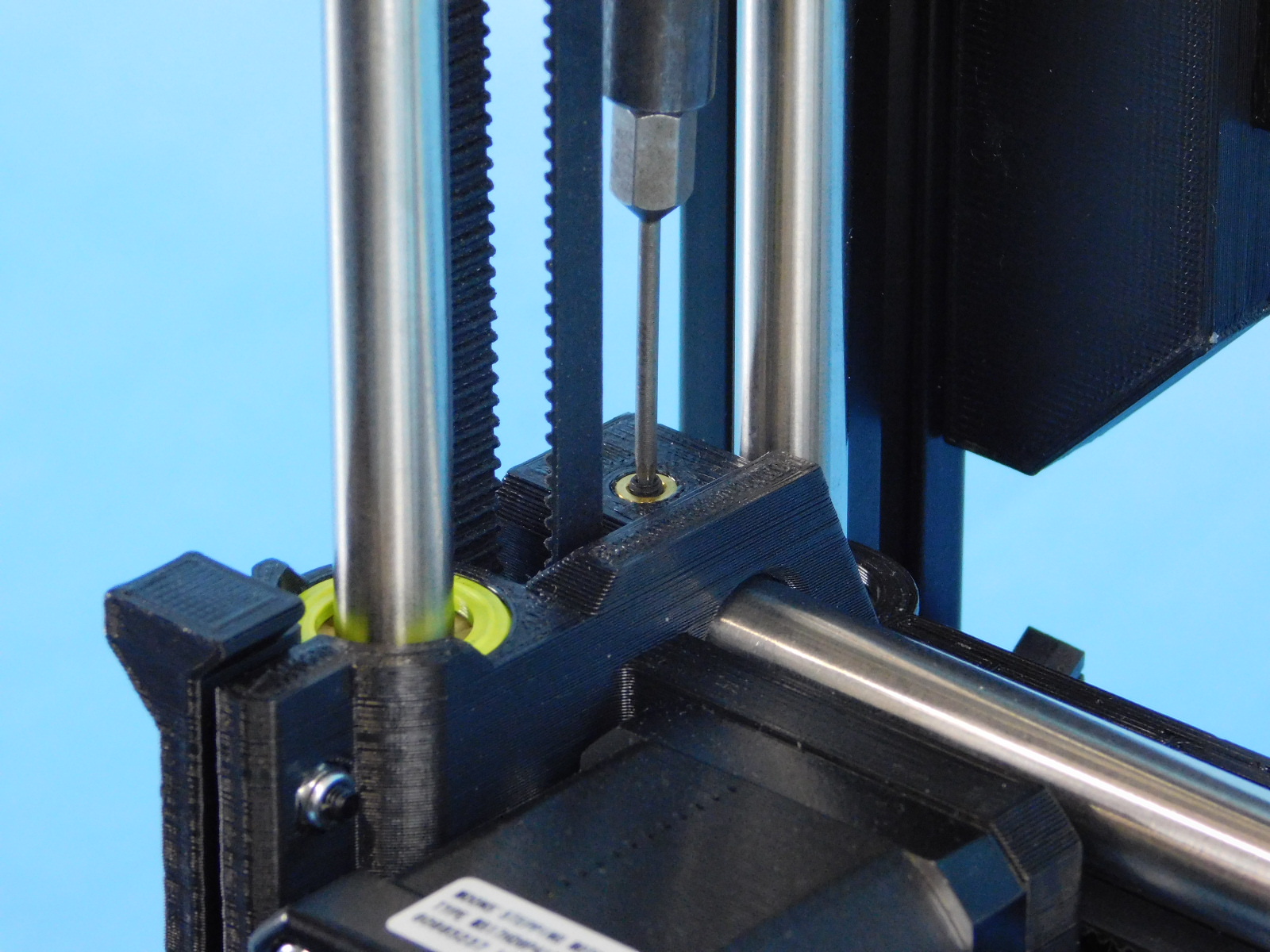
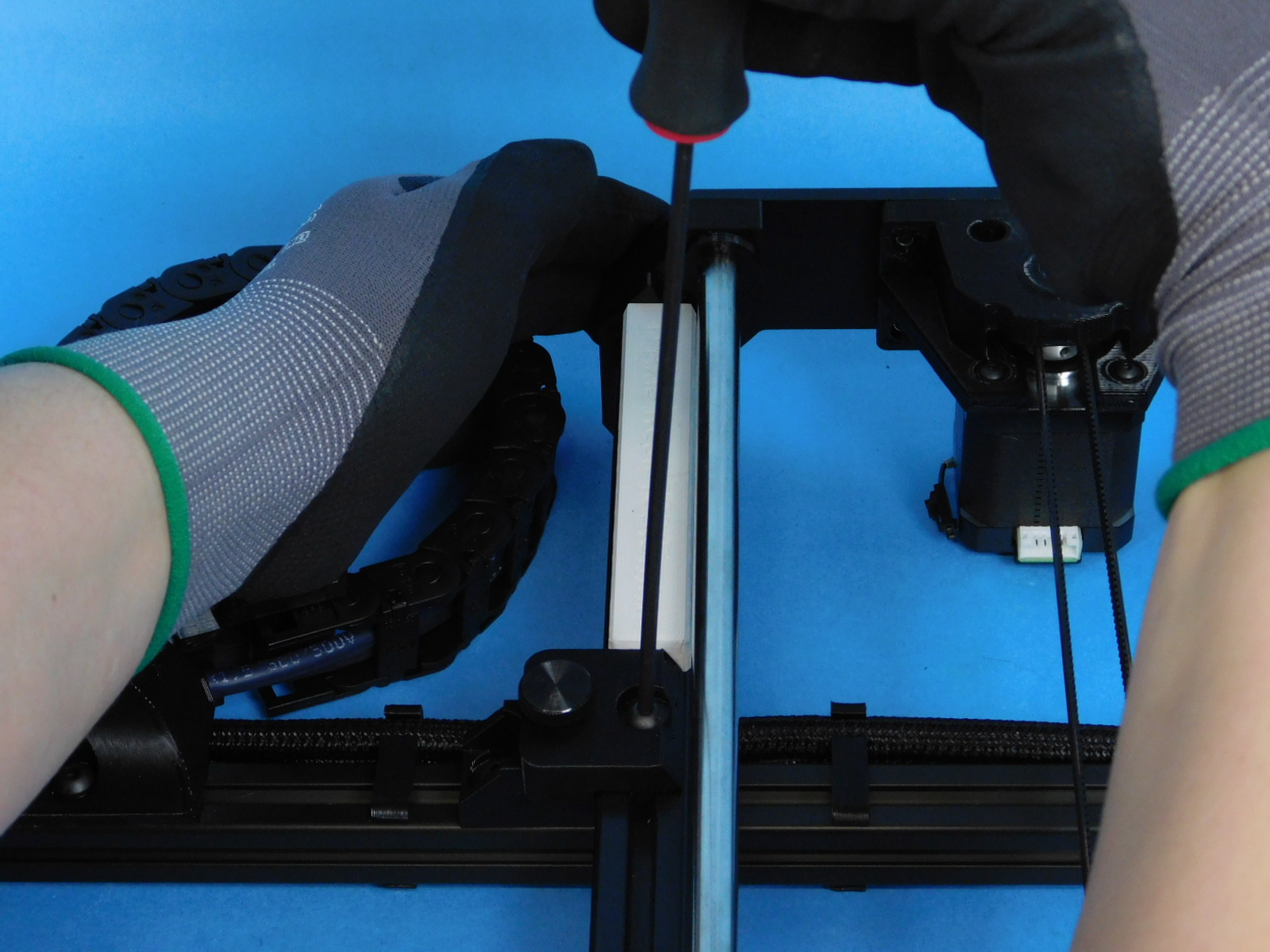
Obtain one 12mm Smooth Rod [HD-RD0066] and slide it through the upper 12mm hole in the X-Idler End from the outside of the frame.
Continue through the upper bearing of the X-Carriage and into the upper 12mm hole of the X-Motor End until the end of the smooth rod is flush with the outside of the X-Idler End.
Torque both upper smooth rod set screws (located on the top side of the X-Ends) to 3in*lbs.


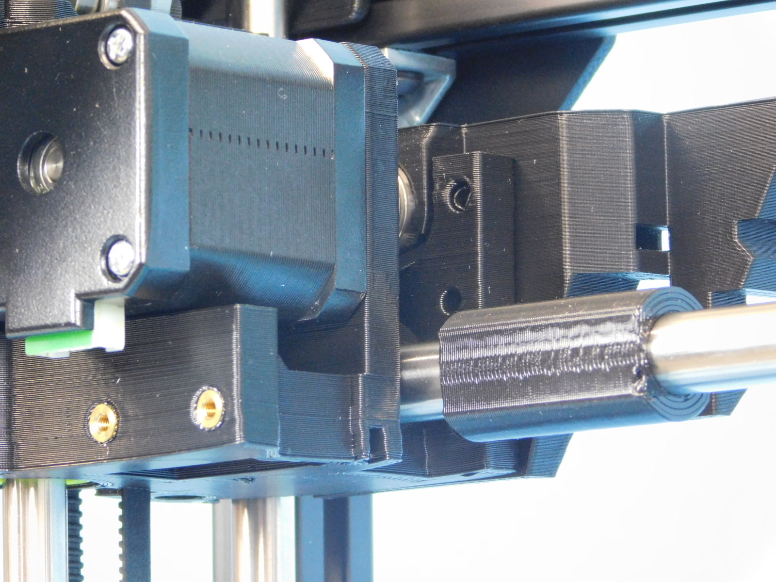
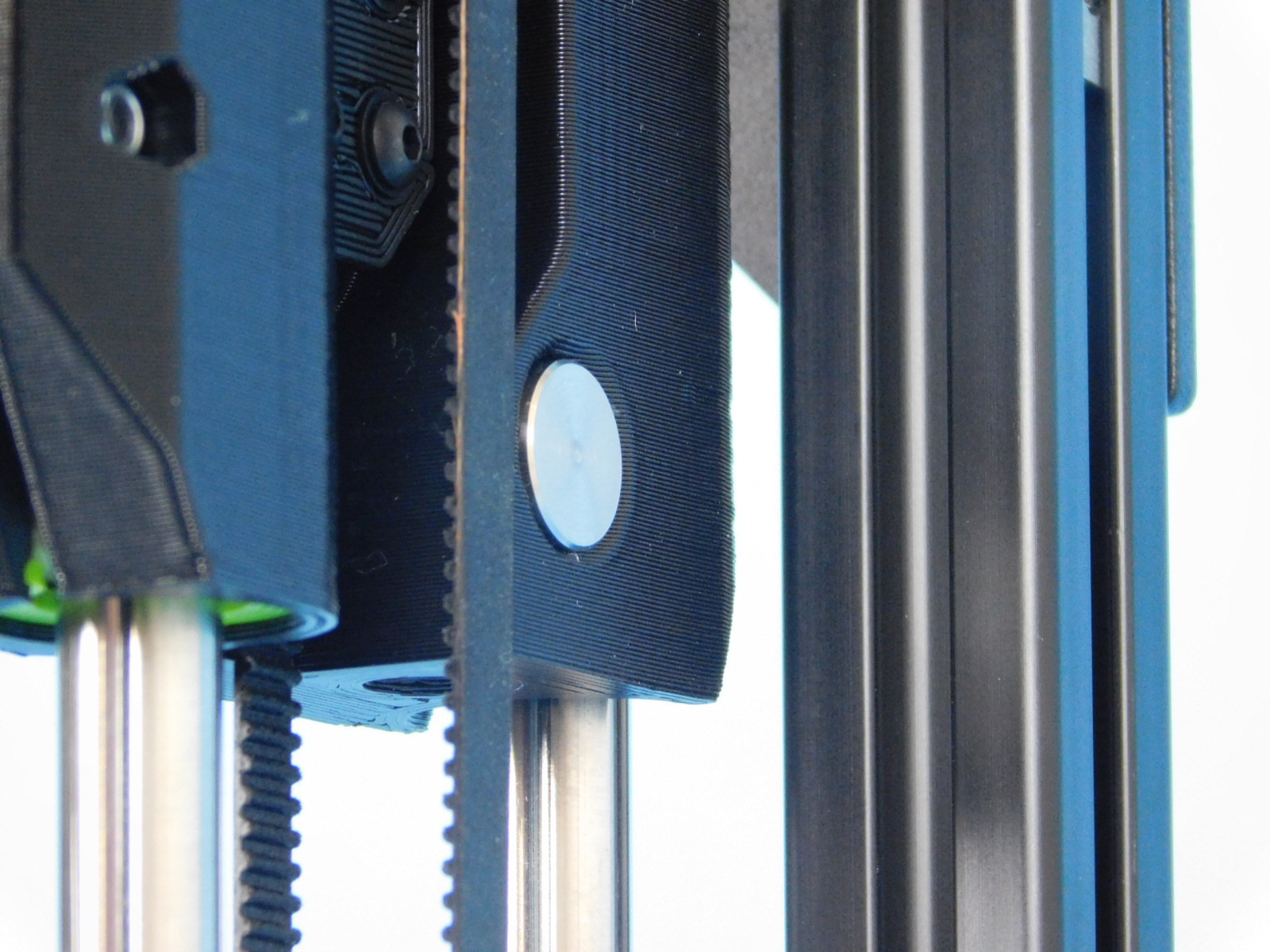
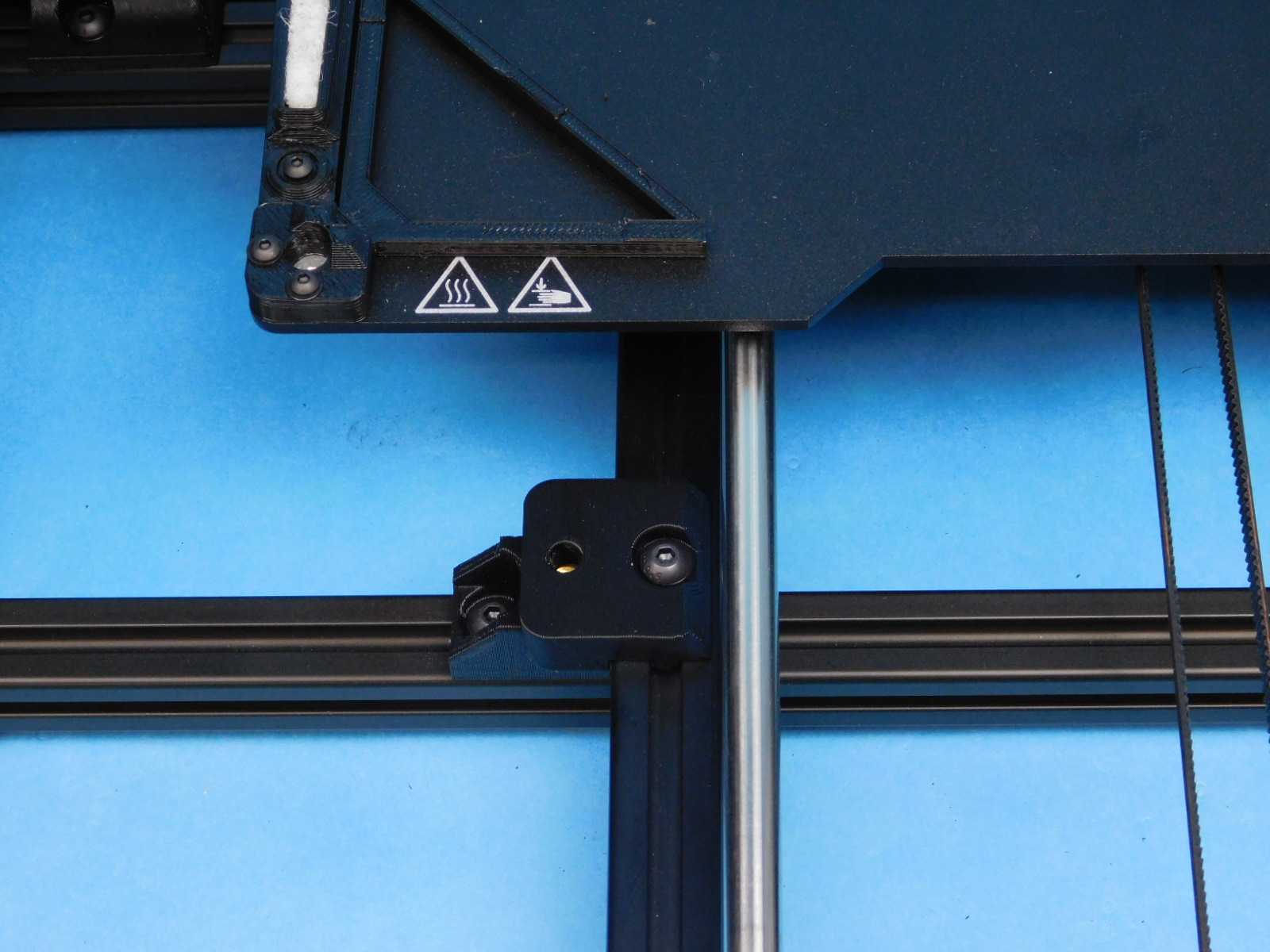
The X-Axis bushings have compression features that allow the printed part to be tightened on the bushings to prevent unwanted motion.
Tighten the lower X-Axis compression bushing by tightening the flat head fastener on the bottom front of the carriage.
Tighten until you can no longer tilt the bushings on the rod, but ensure the bearing can still slide freely left to right.
Do the same for the upper X-Axis compression bushing by tightening the flat head fastener towards the top front of the carriage.
Now we will set the alignment between the upper/lower X Axis bushings.
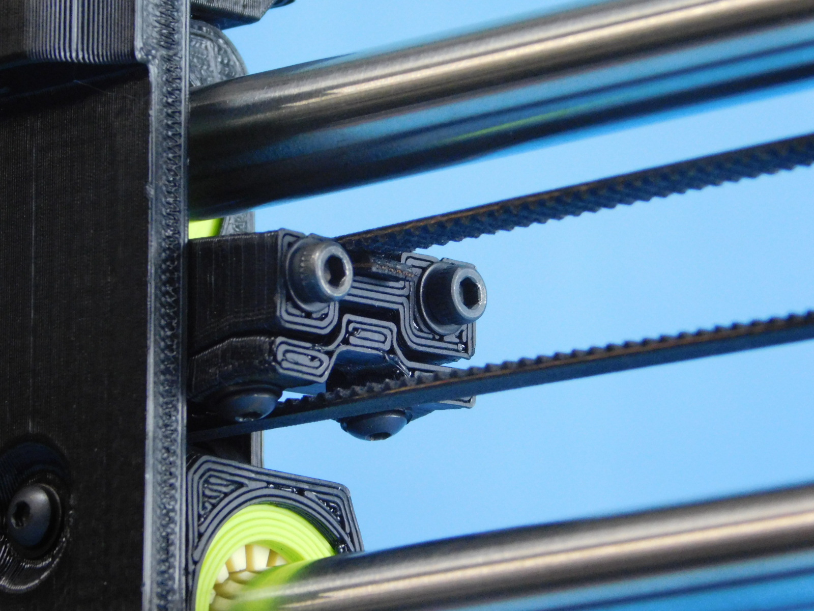
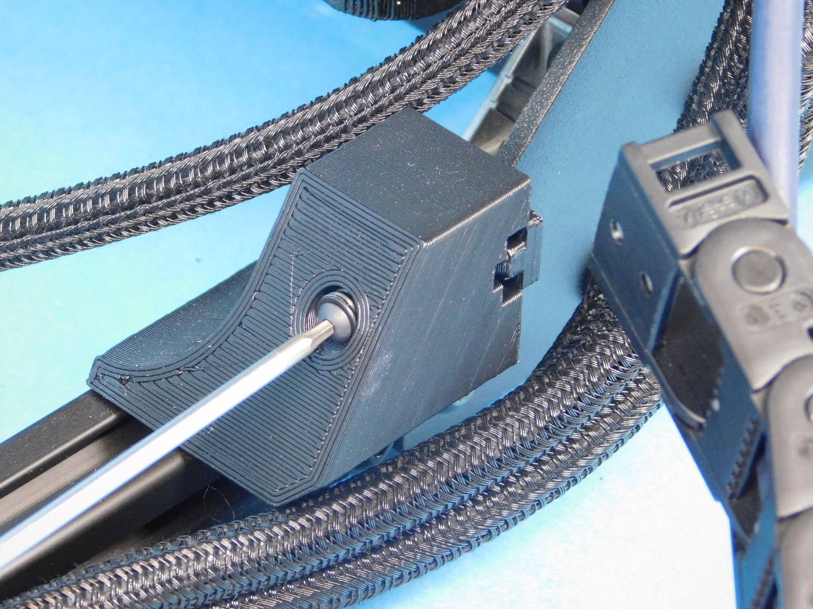
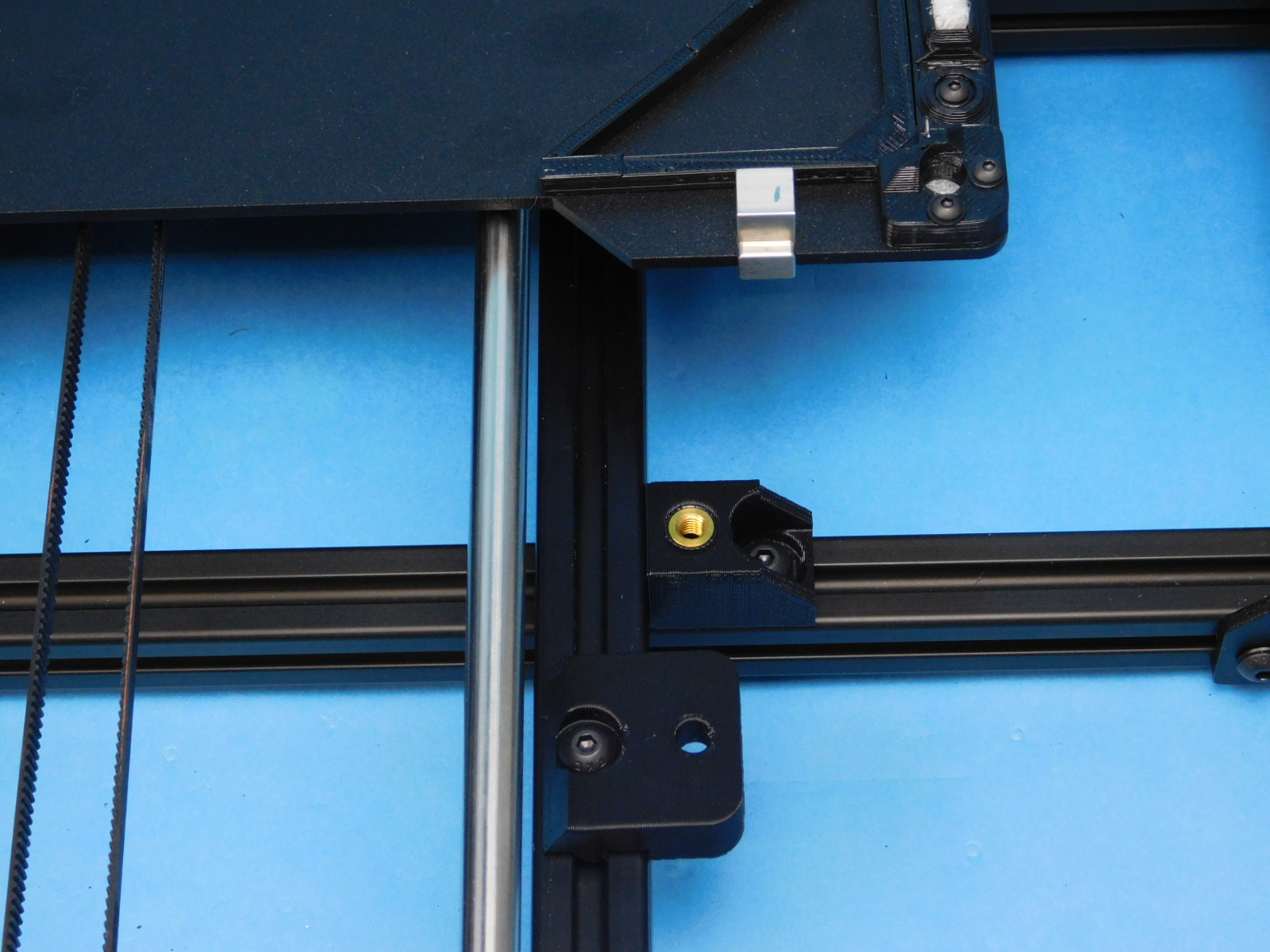
Slide the X Carriage to the left end of travel against the X-Motor End and tighten the left button head fastener on the front of the carriage.
Torque to 5in*lbs
Slide the X Carriage to the right end of travel against the X-Idler End and tighten the right button head fastener on the front of the carriage.
Torque to 5in*lbs

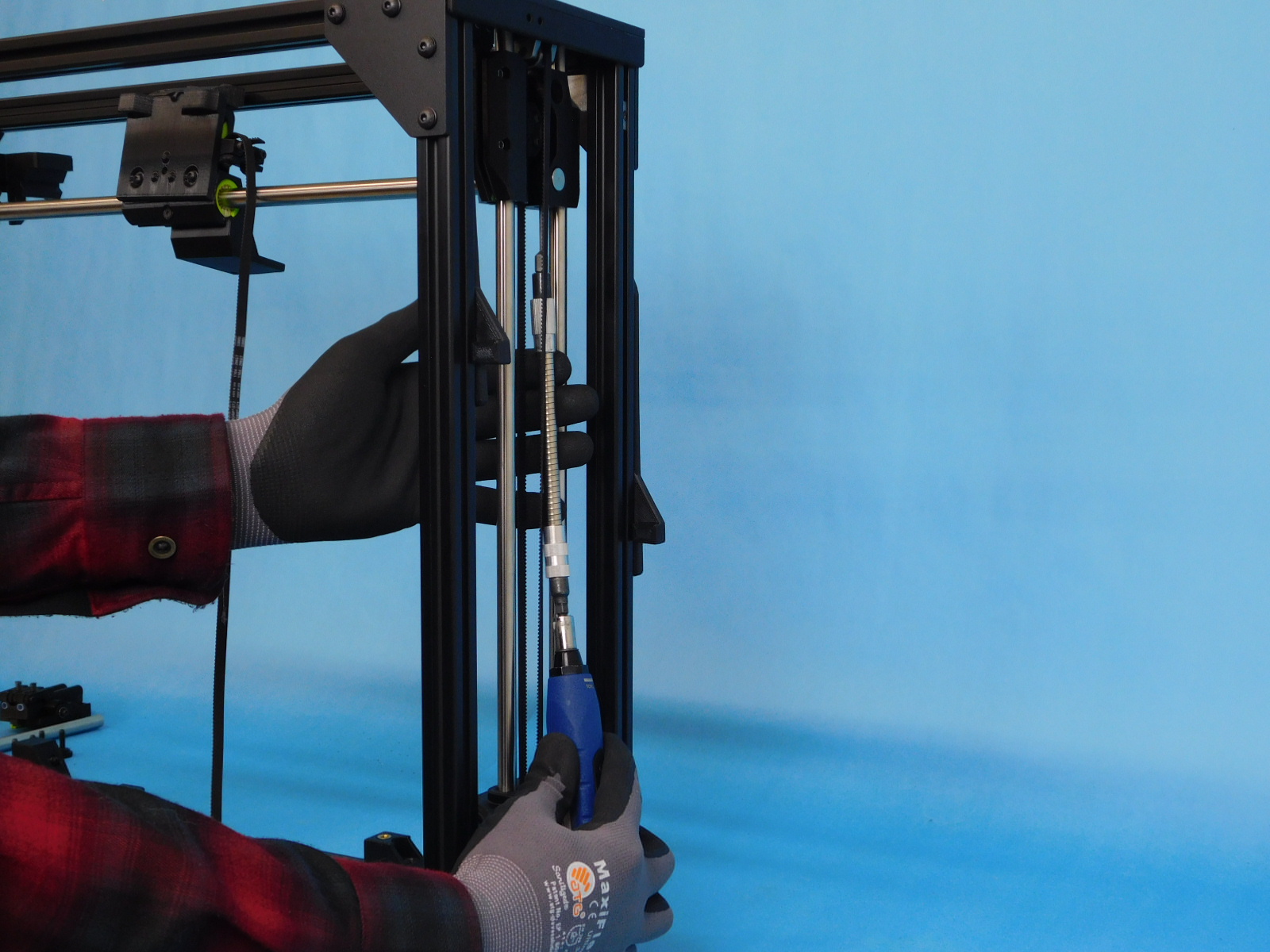
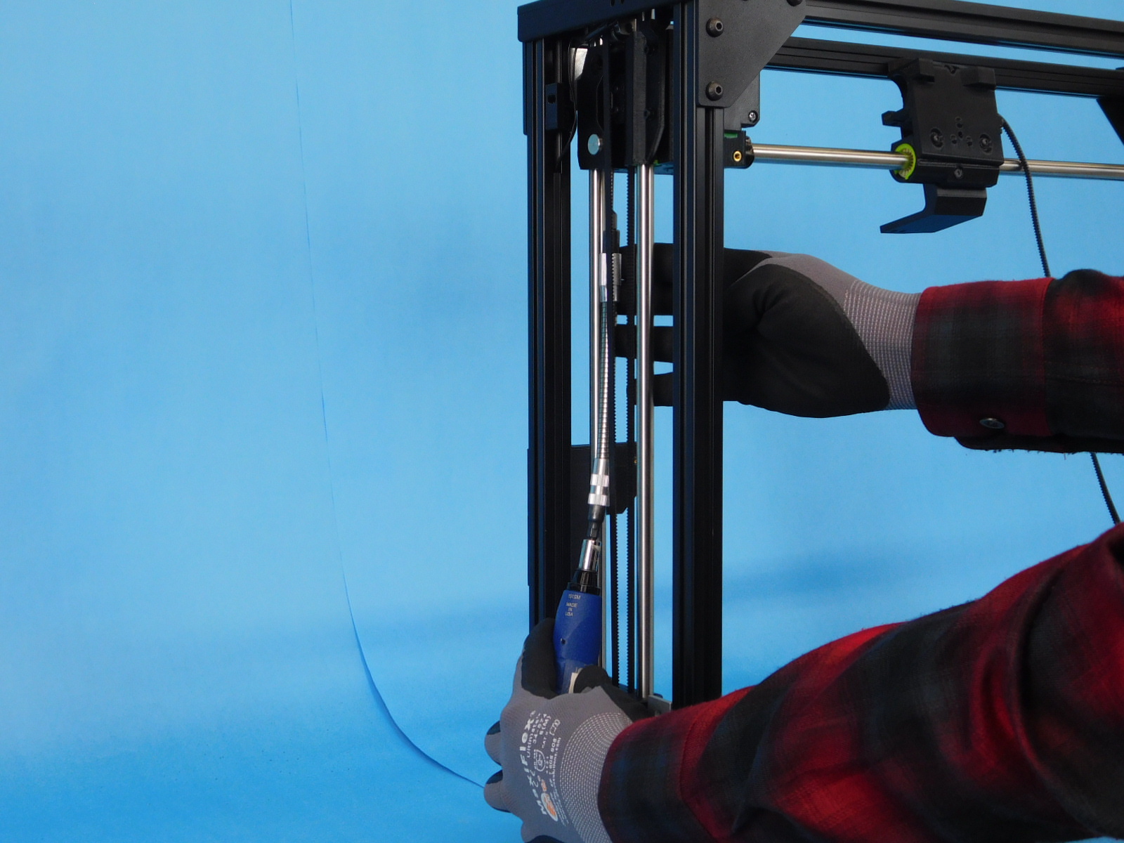
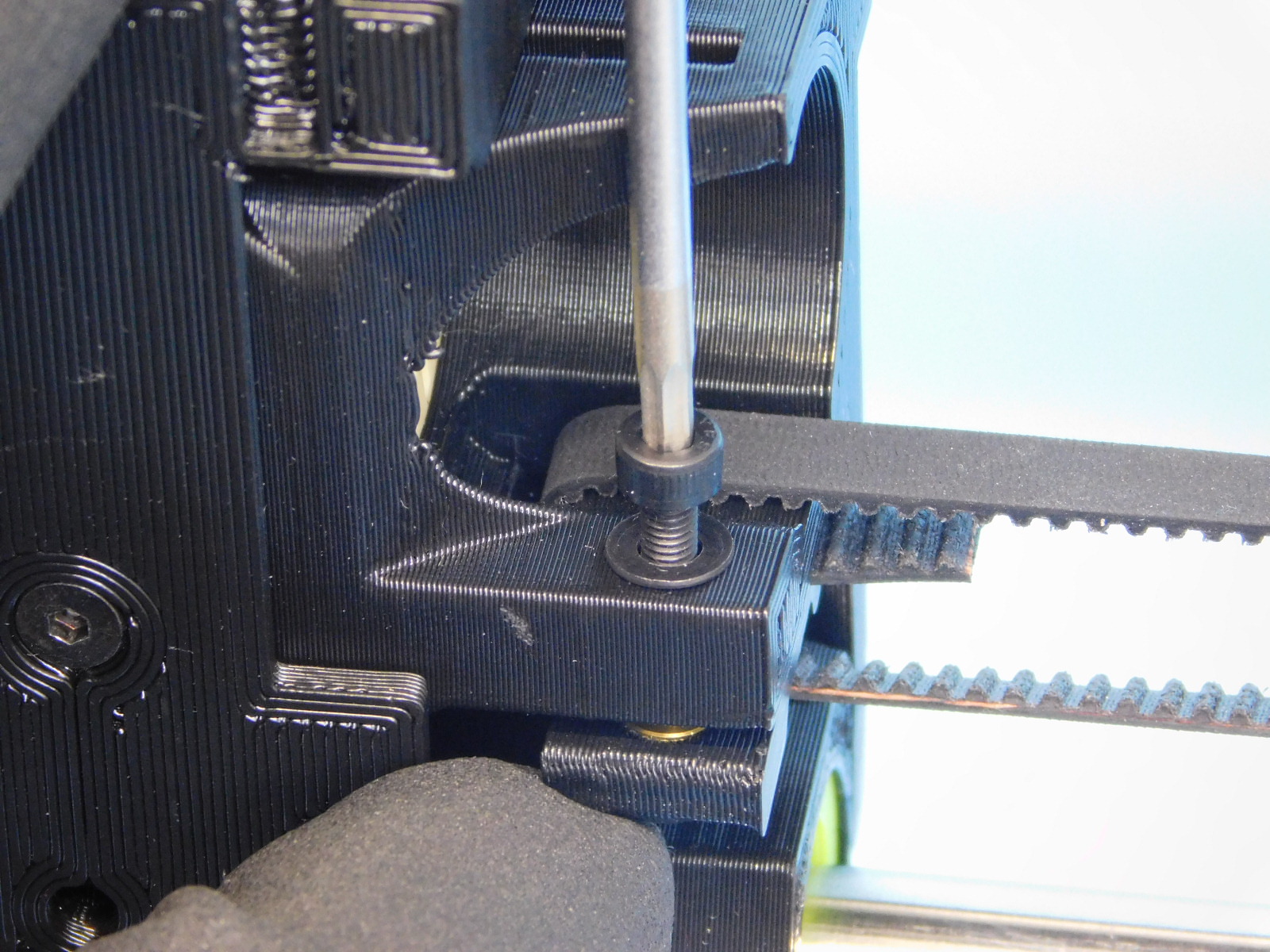
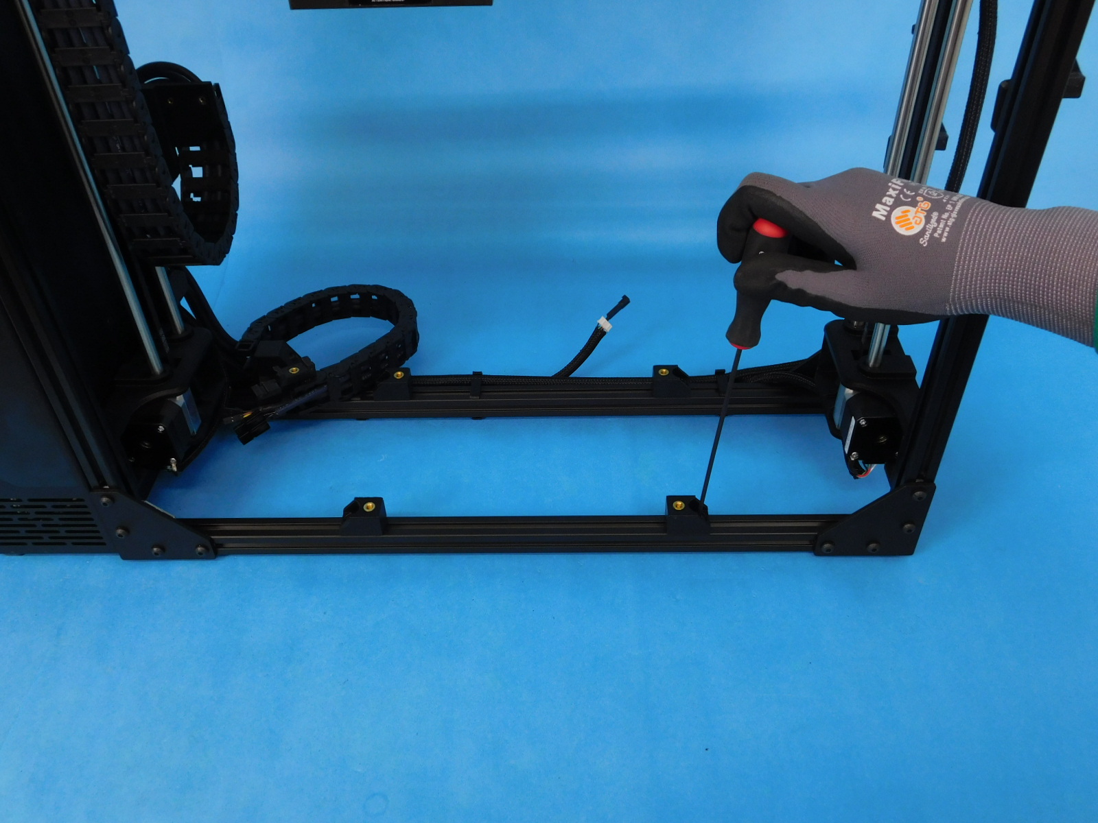
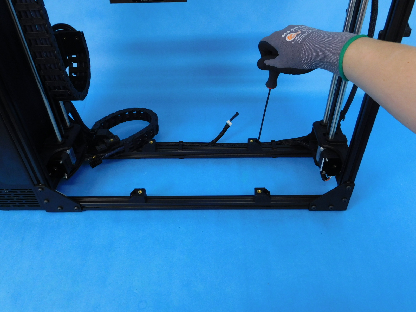
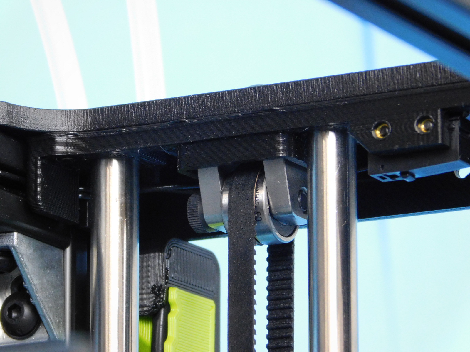
You will need a Gates 508C Sonic Tension Meter on setting number 7
Tighten the X-Belt Tensioner fasteners in even increments until the target tension is reached.
Target: 23-45N
Always ensure measurements are taken at the middle with the X Carriage in the middle; measure the long portion of the belt (closest the lower smooth rod). The portion of belt being measured should not contact anything while being measured; this will cause inaccurate measurements.
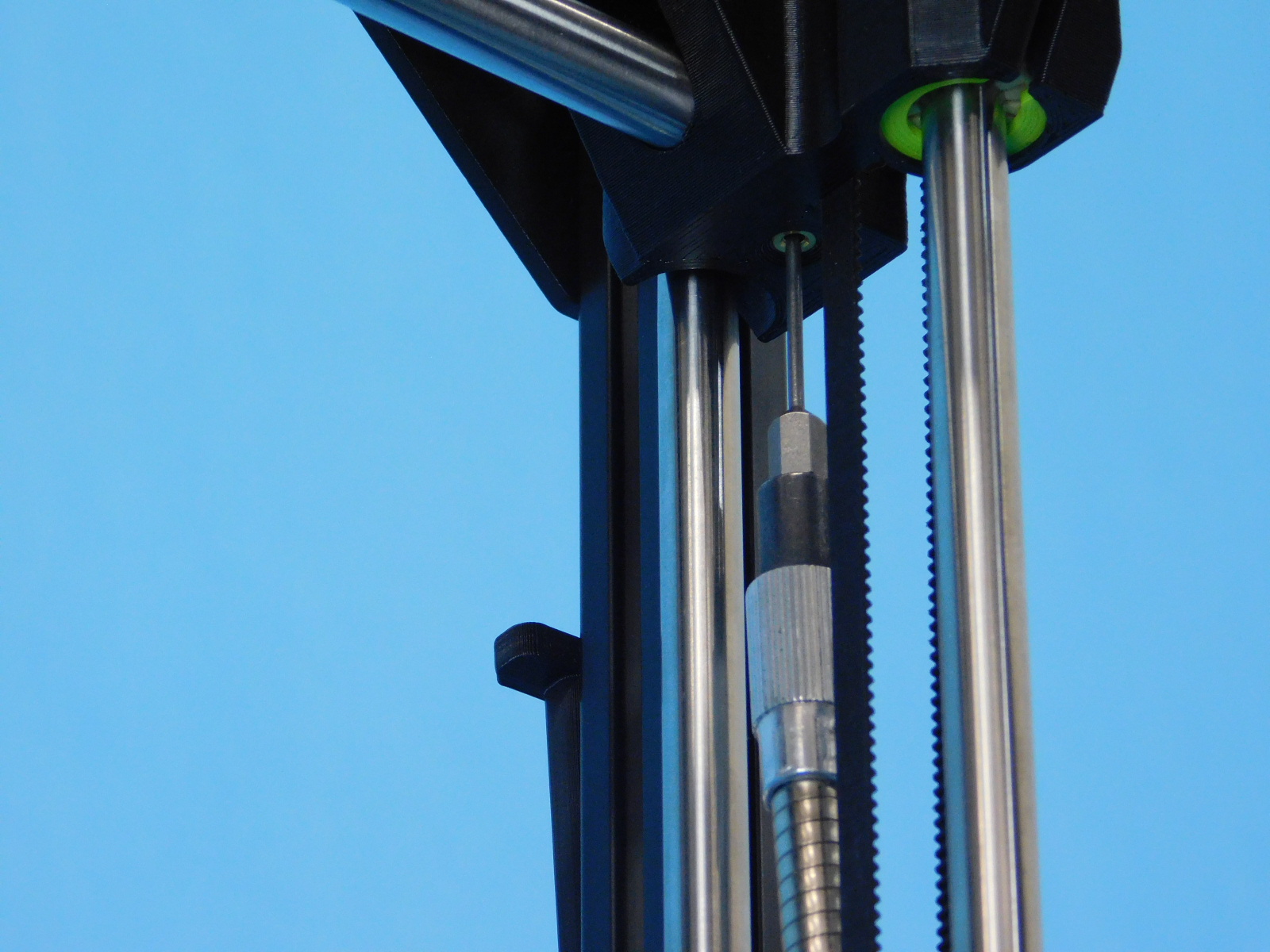
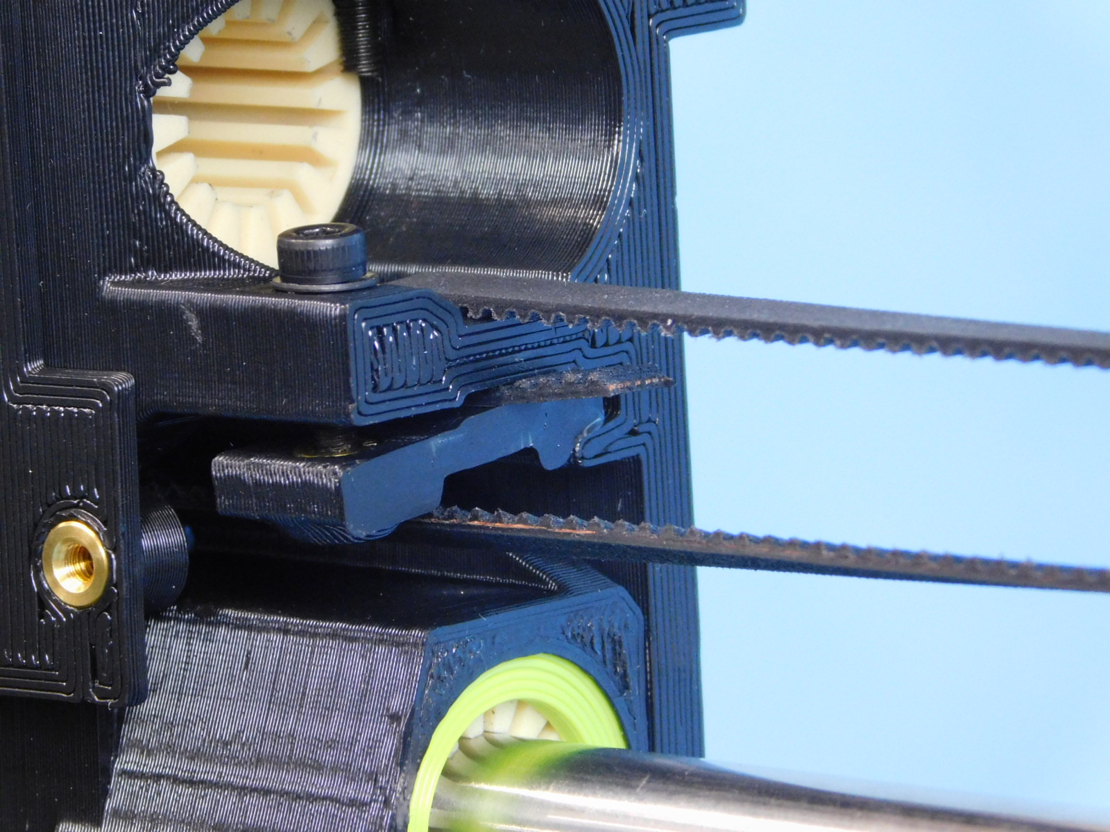
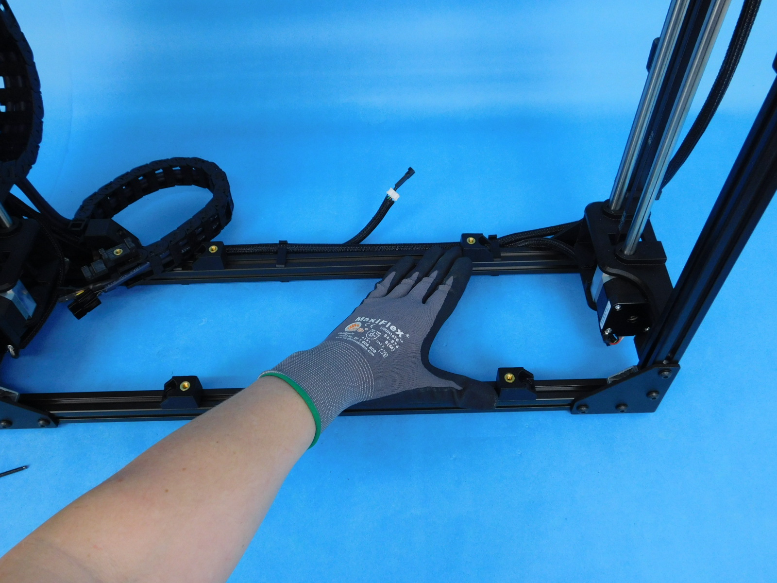
Once tension on the belt is properly set, cut off the excess belt from both sides of the part but leave approximately 10mm protruding from the motor side. This allows for grip should the belt tension need adjusted post-assembly.
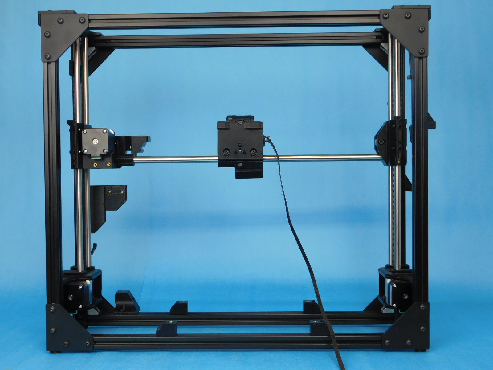
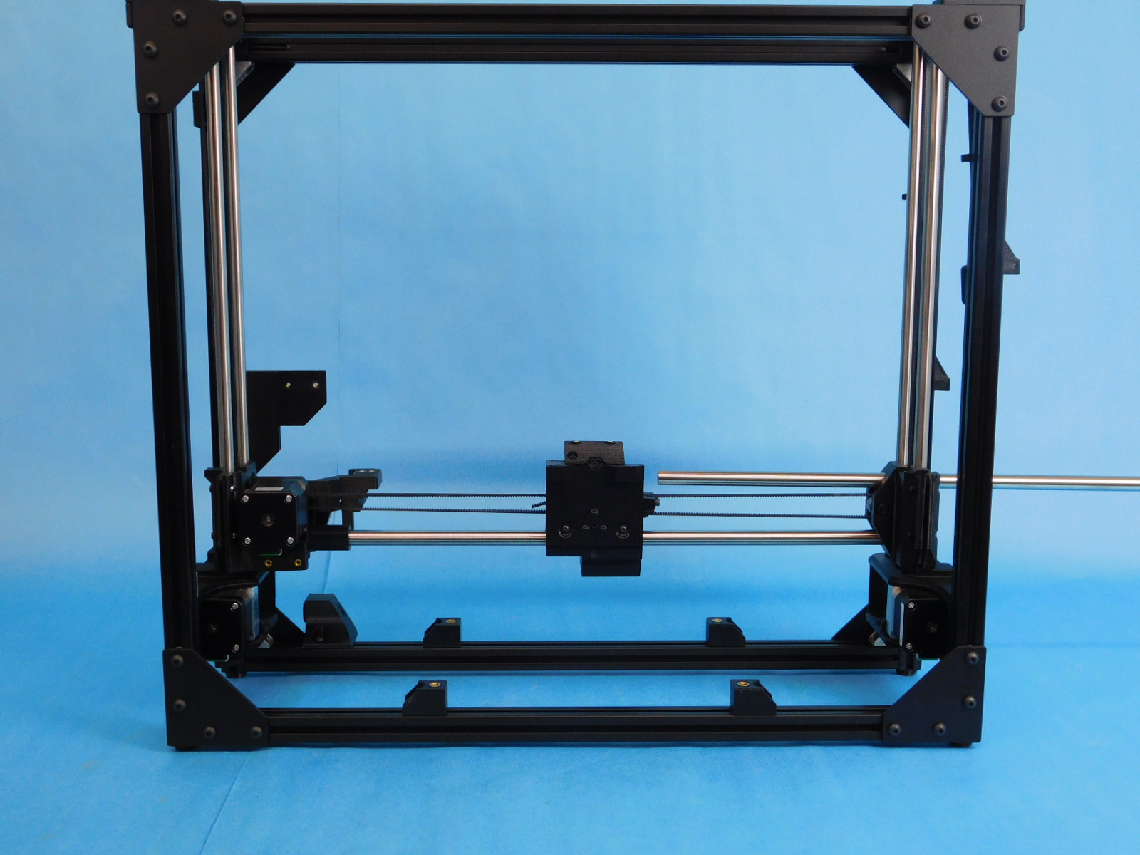
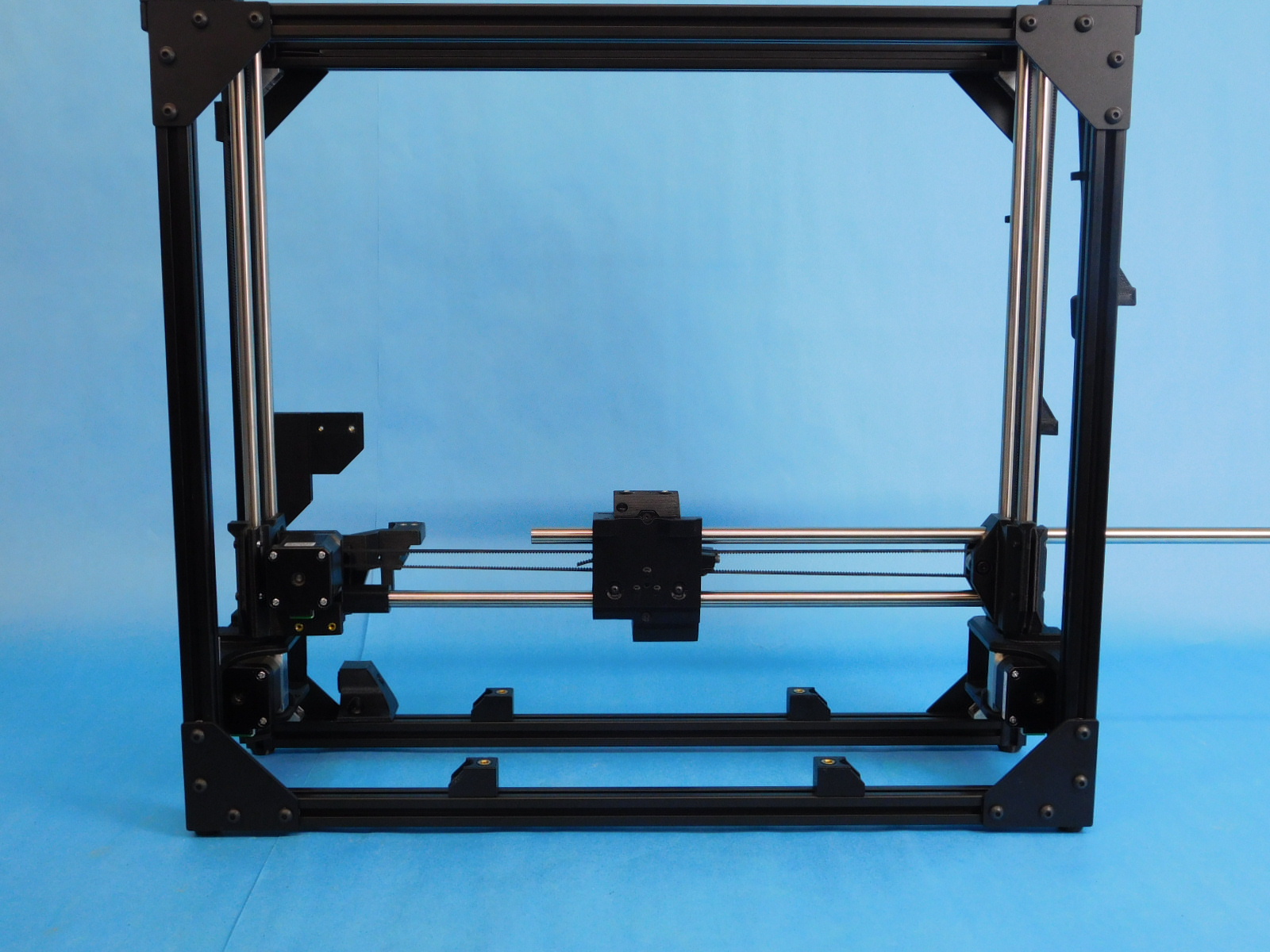
Set the frame with the front facing you on its left side, towards the side or rear of your workbench.
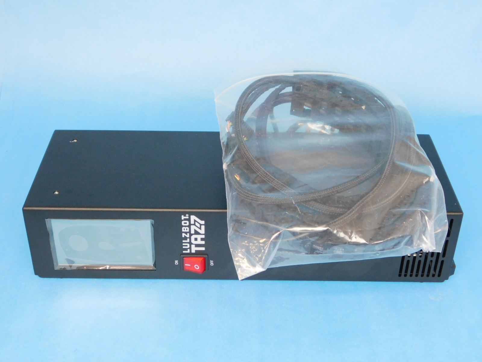
Obtain one Control Box Assembly [AS-PR0120]
Place the Control Box Assembly cover side down on the workbench with the screen facing you.
Pick up the frame (still with front side facing you and the left side facing down) and place it on top of the Control Box Assembly.
The Z-Max wires will rest in the groove as pictured, ensure they are not pinched when installing the Control Box Assembly.
Place one Stainless M5x10 BHCS [HD-BT0225] with M5 Zinc-plated washer [HD-WA0007] into the metal case mount along the front extrusion to your left.
You will need to lift/hold the frame slightly to insert the fastener, you may also need to loosen the fastener attaching the bracket to the frame to align it with the threaded hole in the Control Box
Thread the fastener into the Control Box, do not tighten yet.
Secure the frame to the Control Box at the other 3 locations using three M5x10 BHCS [HD-BT0073] with washers [HD-WA0040].
Torque all 4 fasteners securing the mounts to the control box to 5in*lbs
Leave the fasteners securing the mounts to the frame loose until the next step.


Pick up and rotate the assembly clockwise 90 degrees, set it down.
Ensure all four feet of the frame and both feet on the bottom of the Control Box are resting flat on the workbench.
The Control Box should neither be too high or too low in relation to the frame assembly. Use the granite block if you are not confident in the flatness of your workbench.
Tighten all four fasteners securing the Control Box Mounts to the frame using a long shank ball-tipped 3mm hex driver. Tighten securely

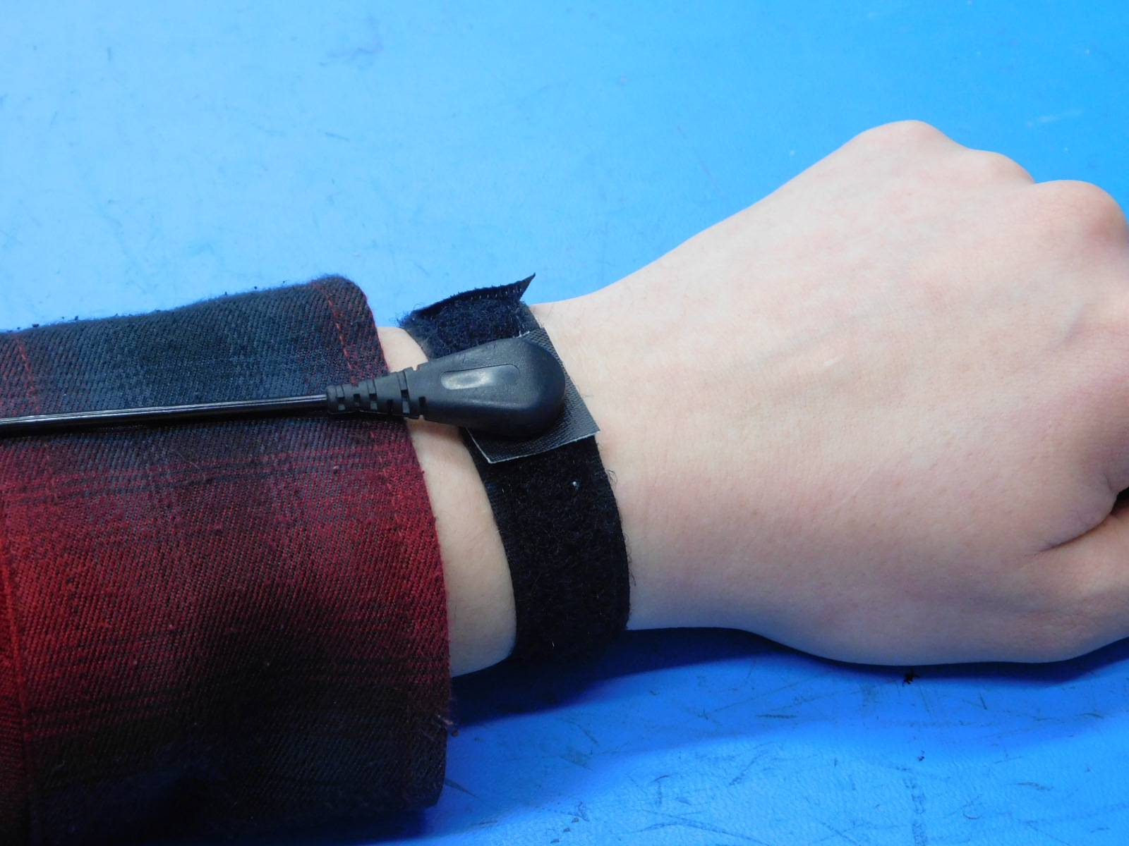
Ensure you are properly grounded via properly connected wrist strap while handling any PCBA
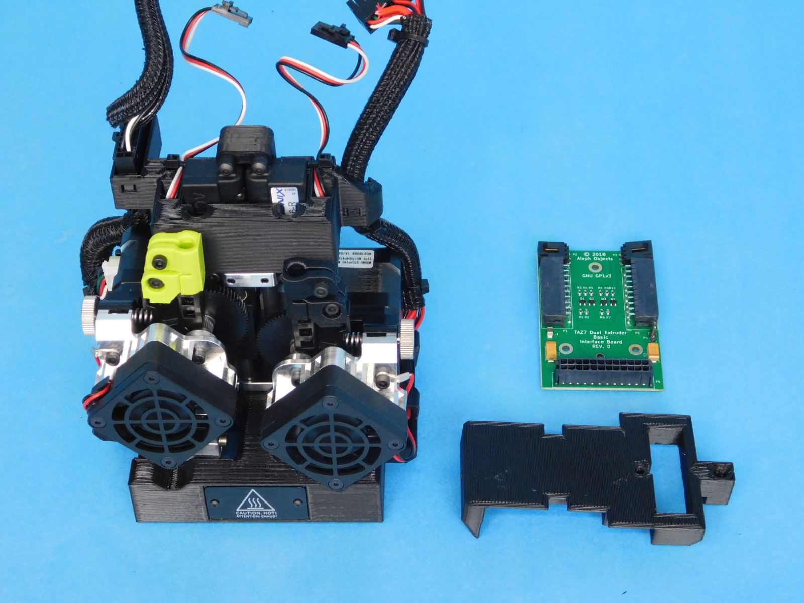
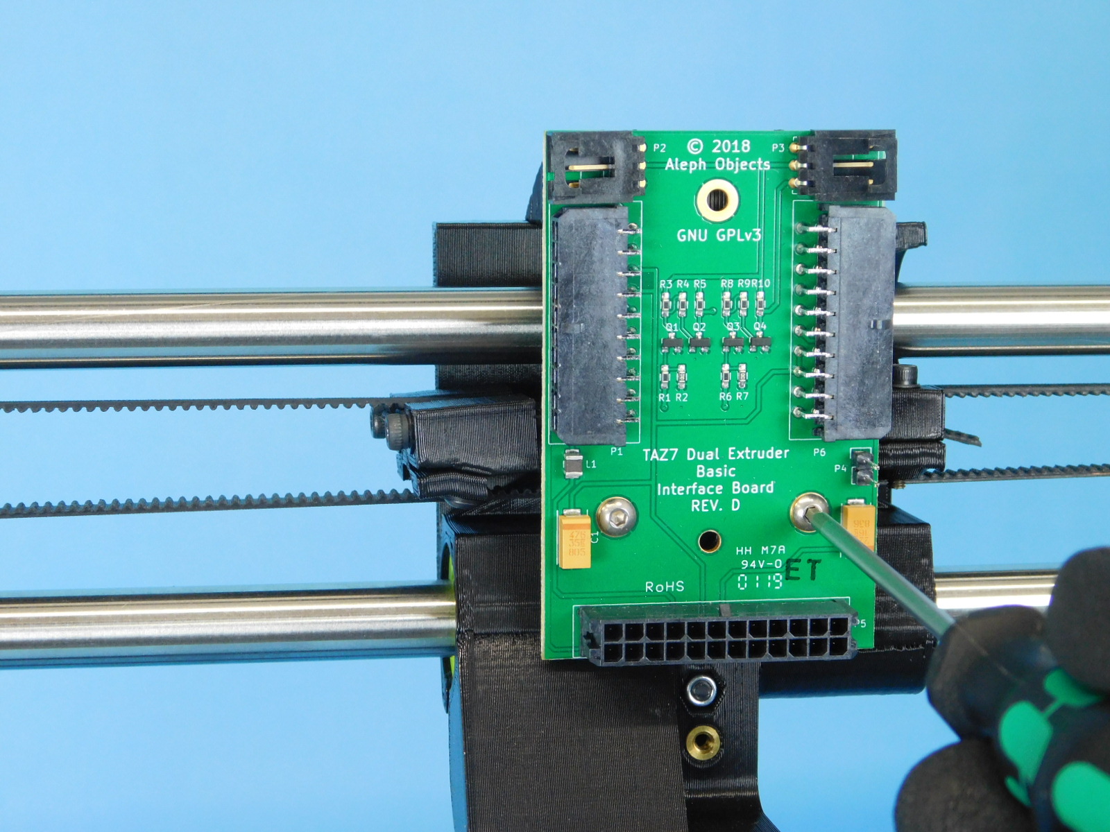
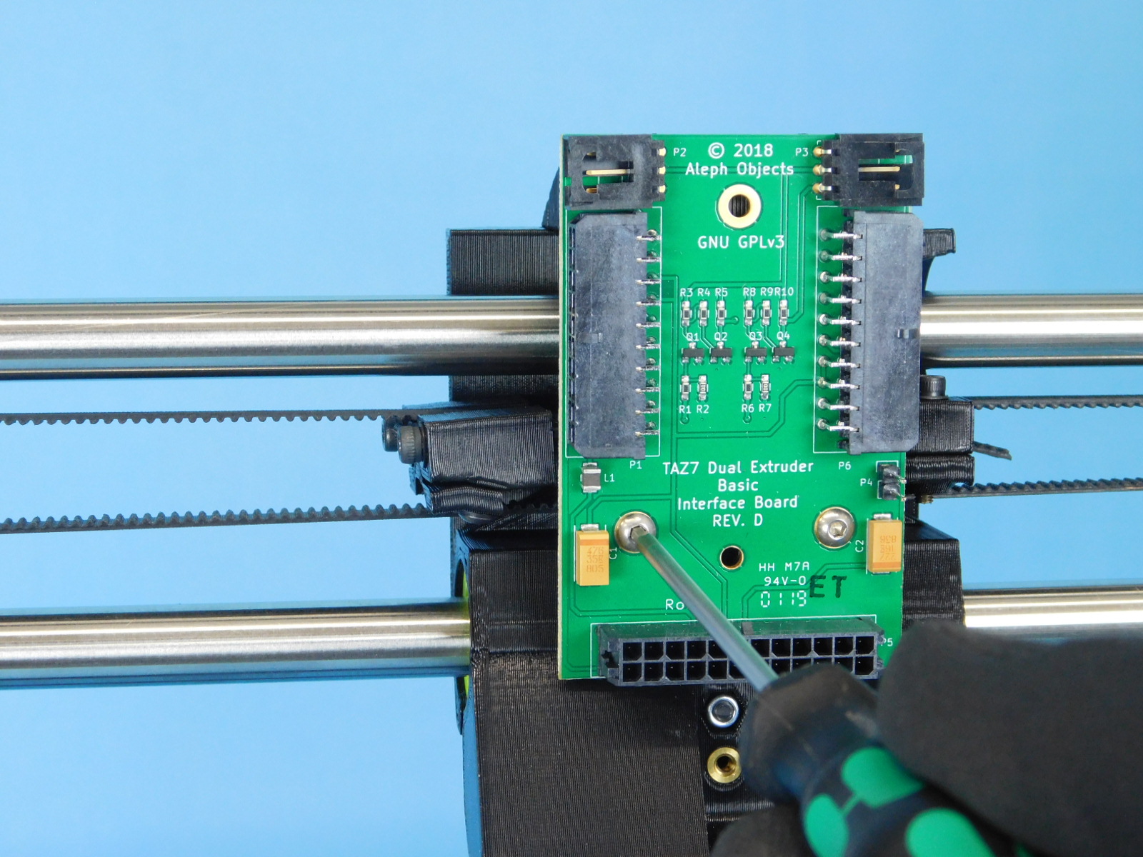
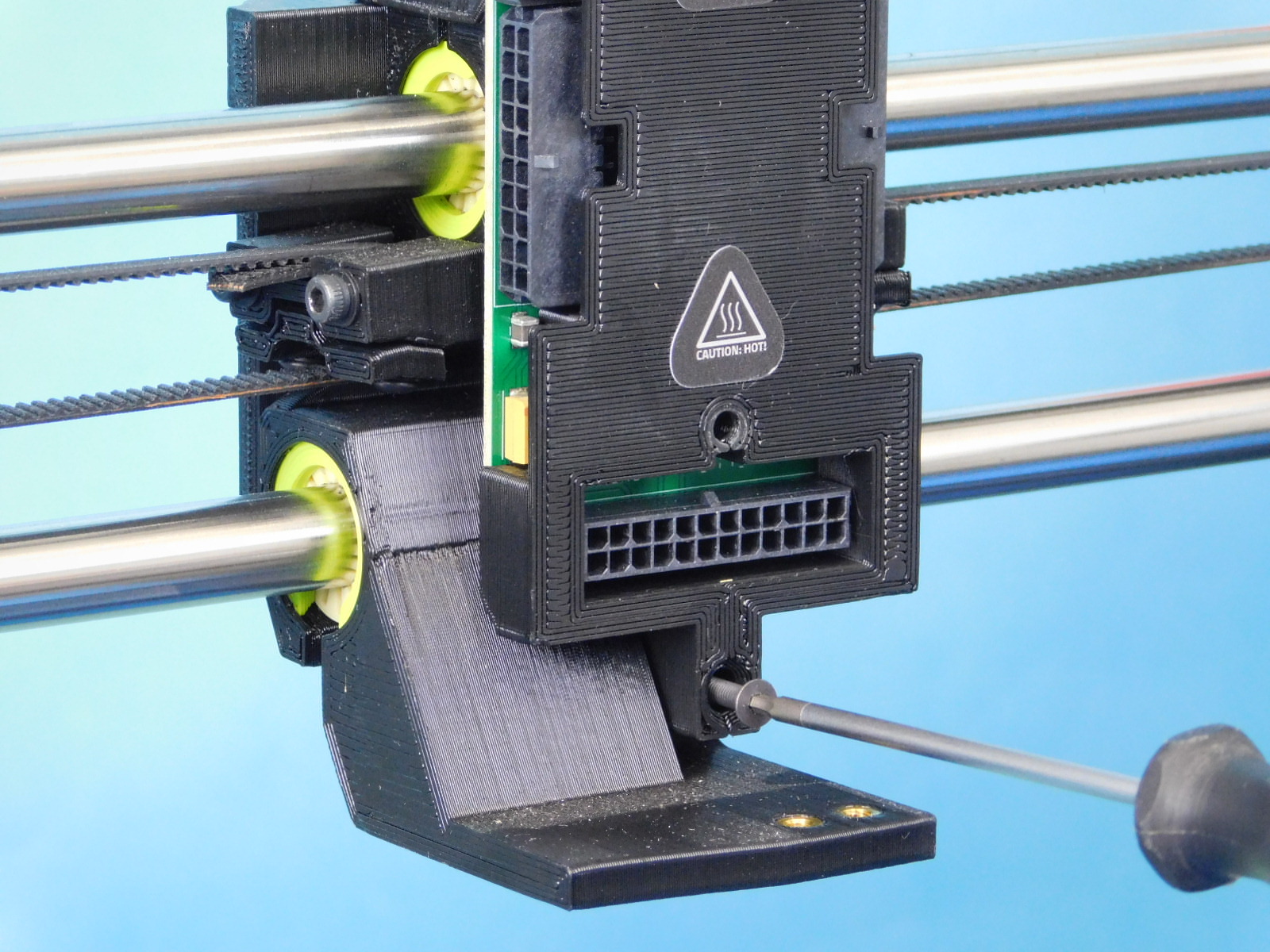
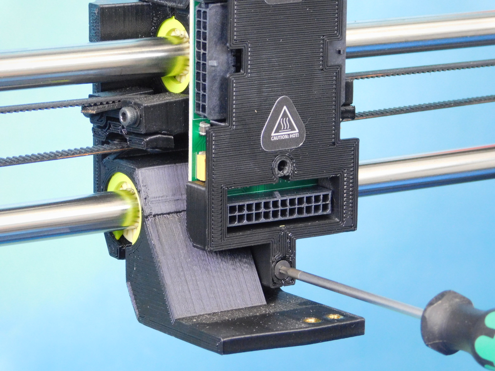
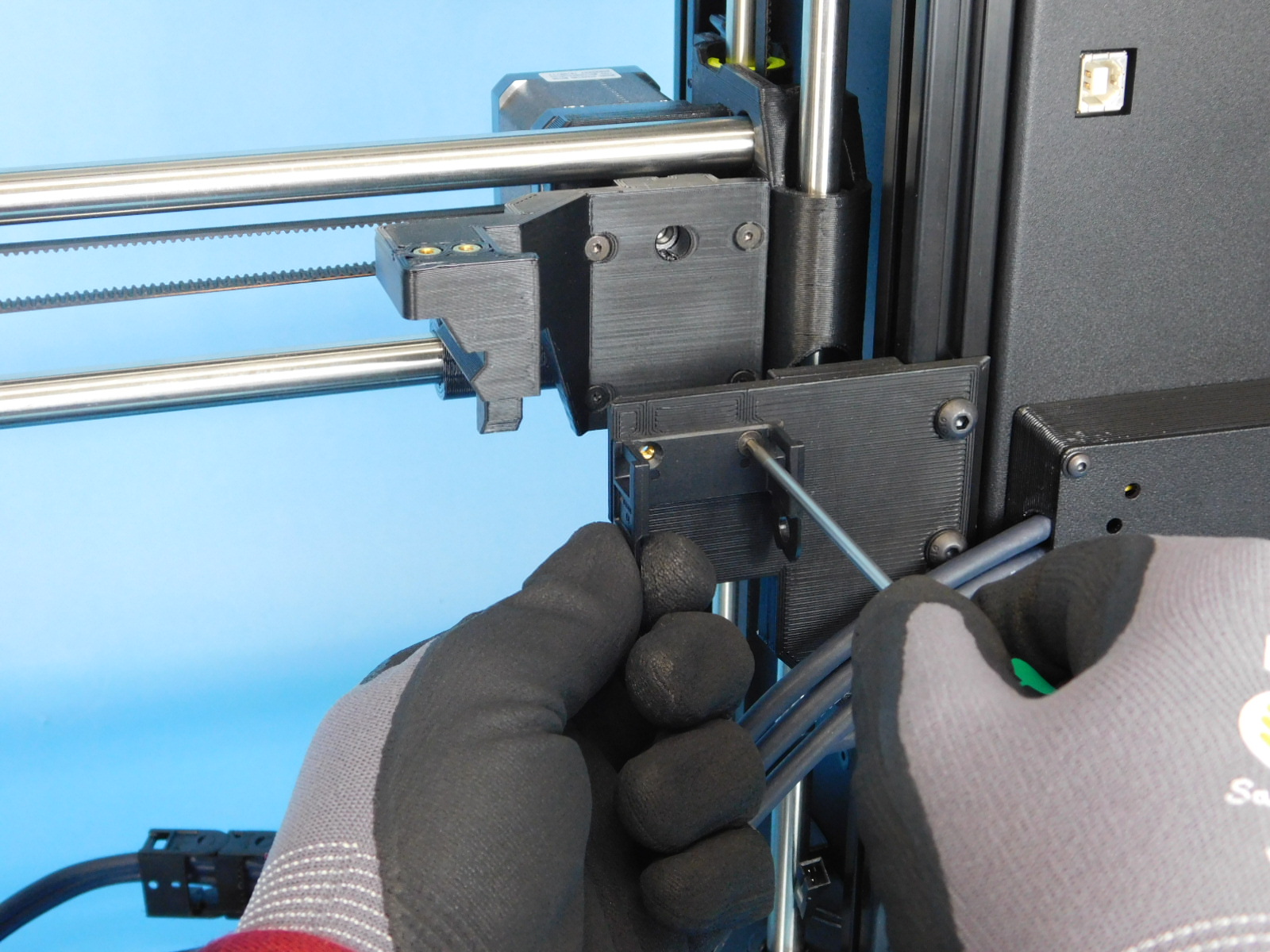
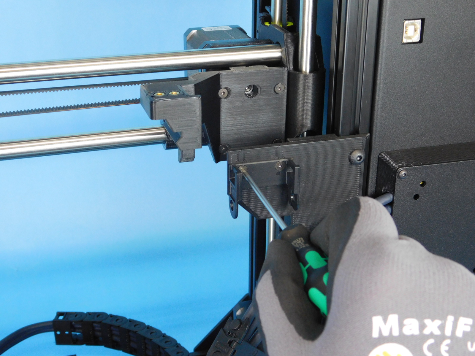
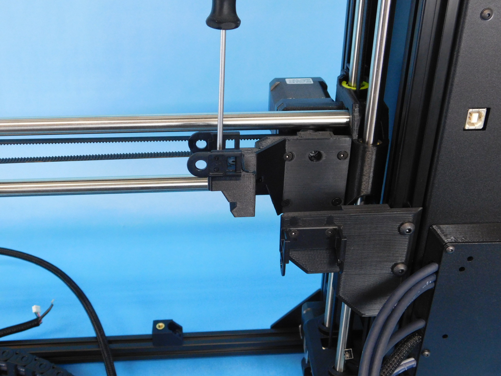
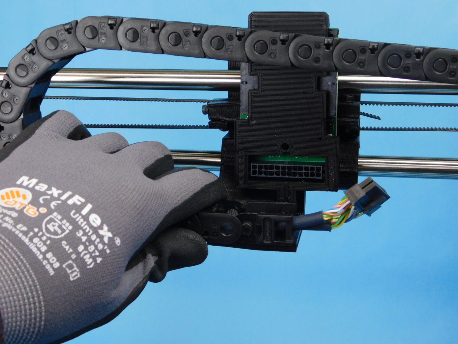
Obtain one Dual Interface Board [PC-BD0111]
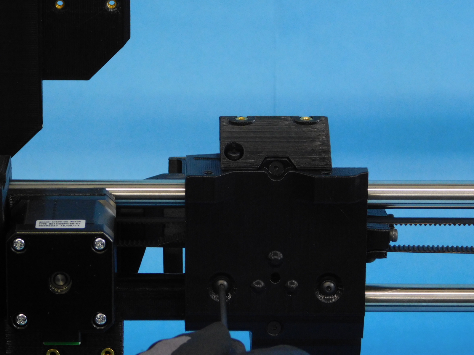
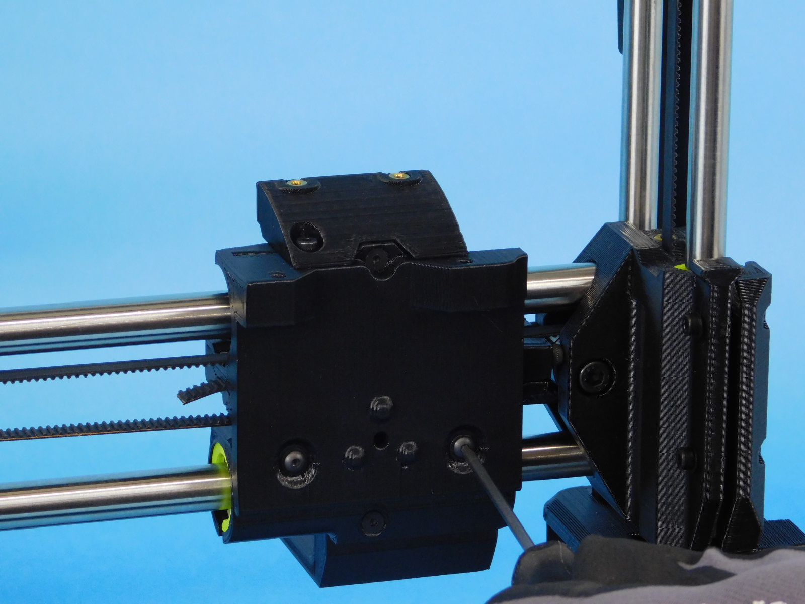
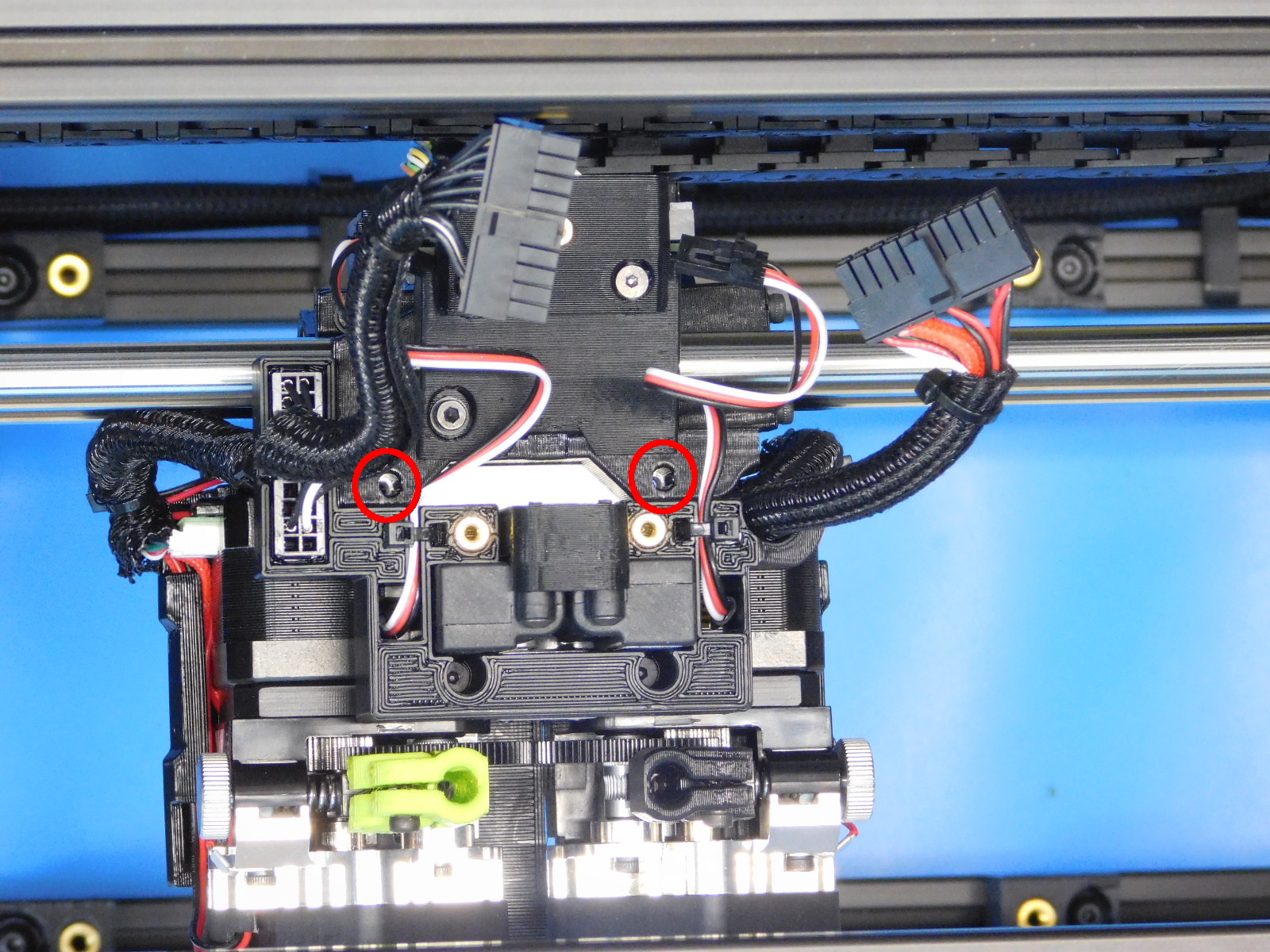
Secure the Dual Interface Board [PC-BD0111] to the rear of the carriage, oriented as pictured, using 2x- M3x8 Stainless BHCS [HD-BT0104].
Torque to 5in*lbs
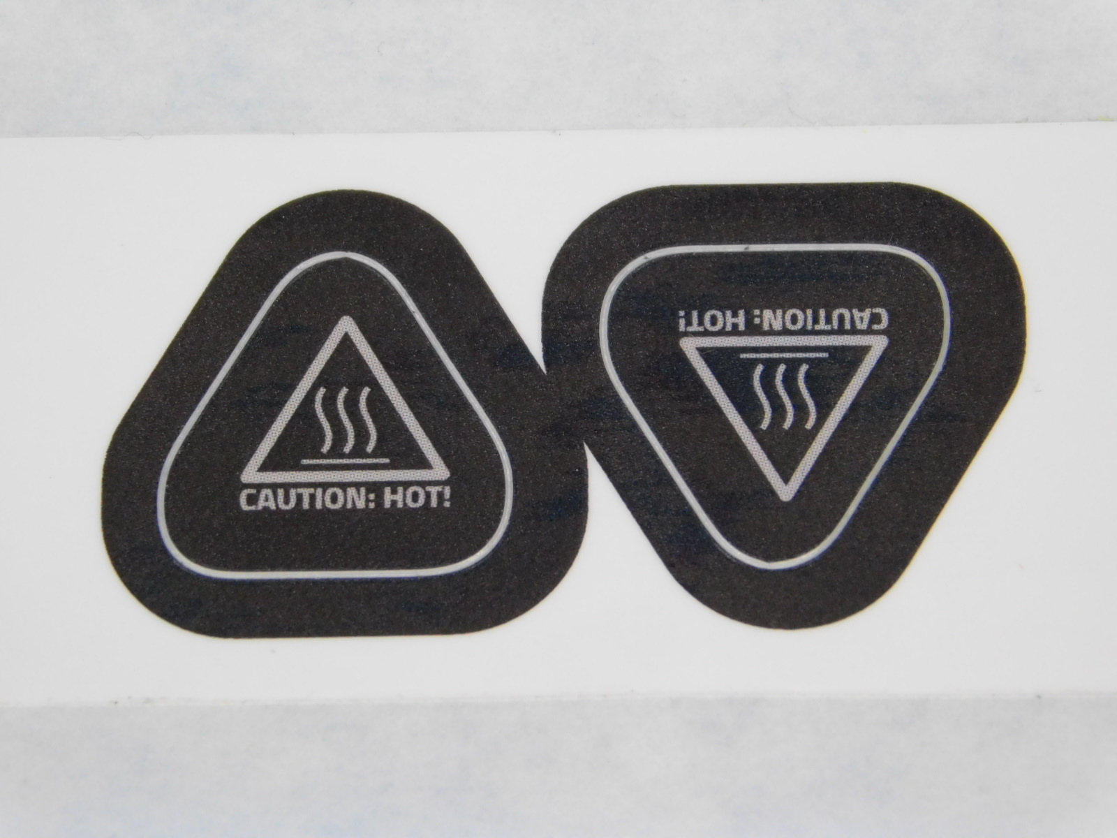
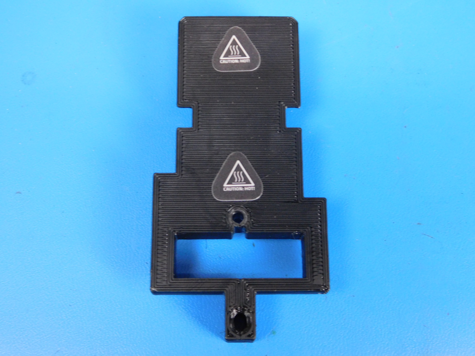
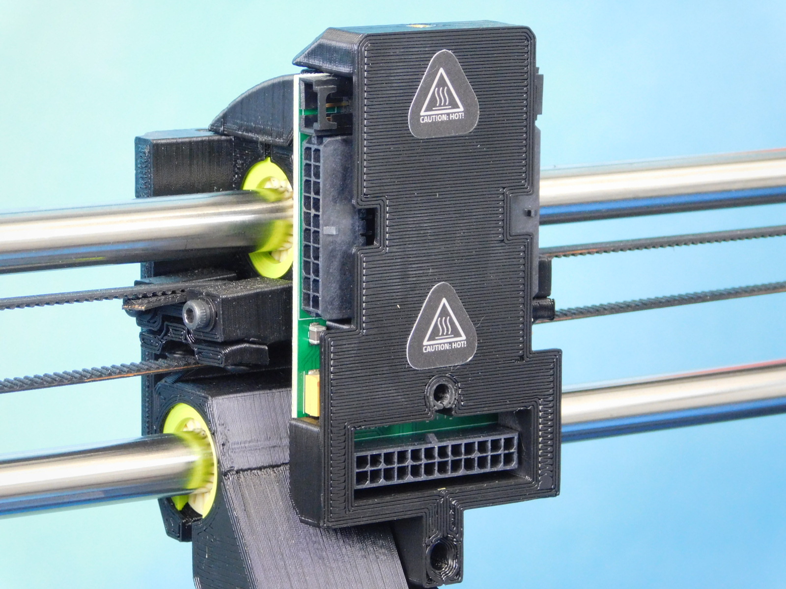
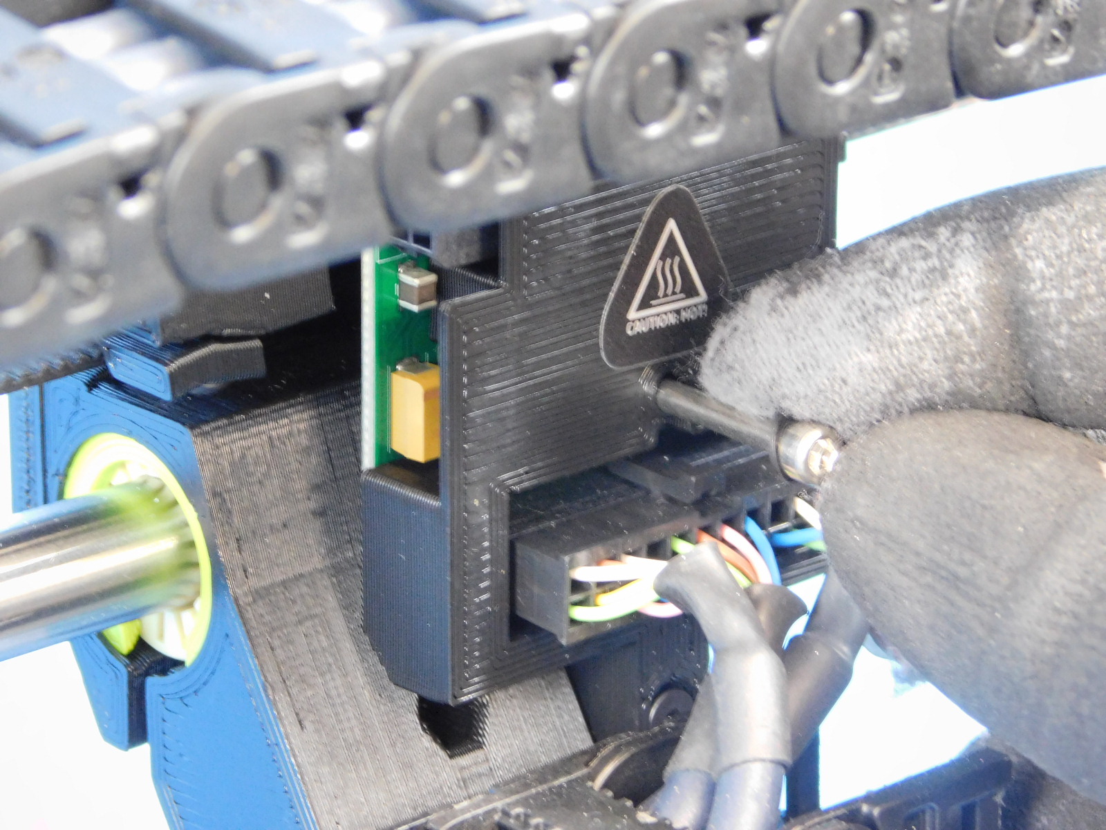
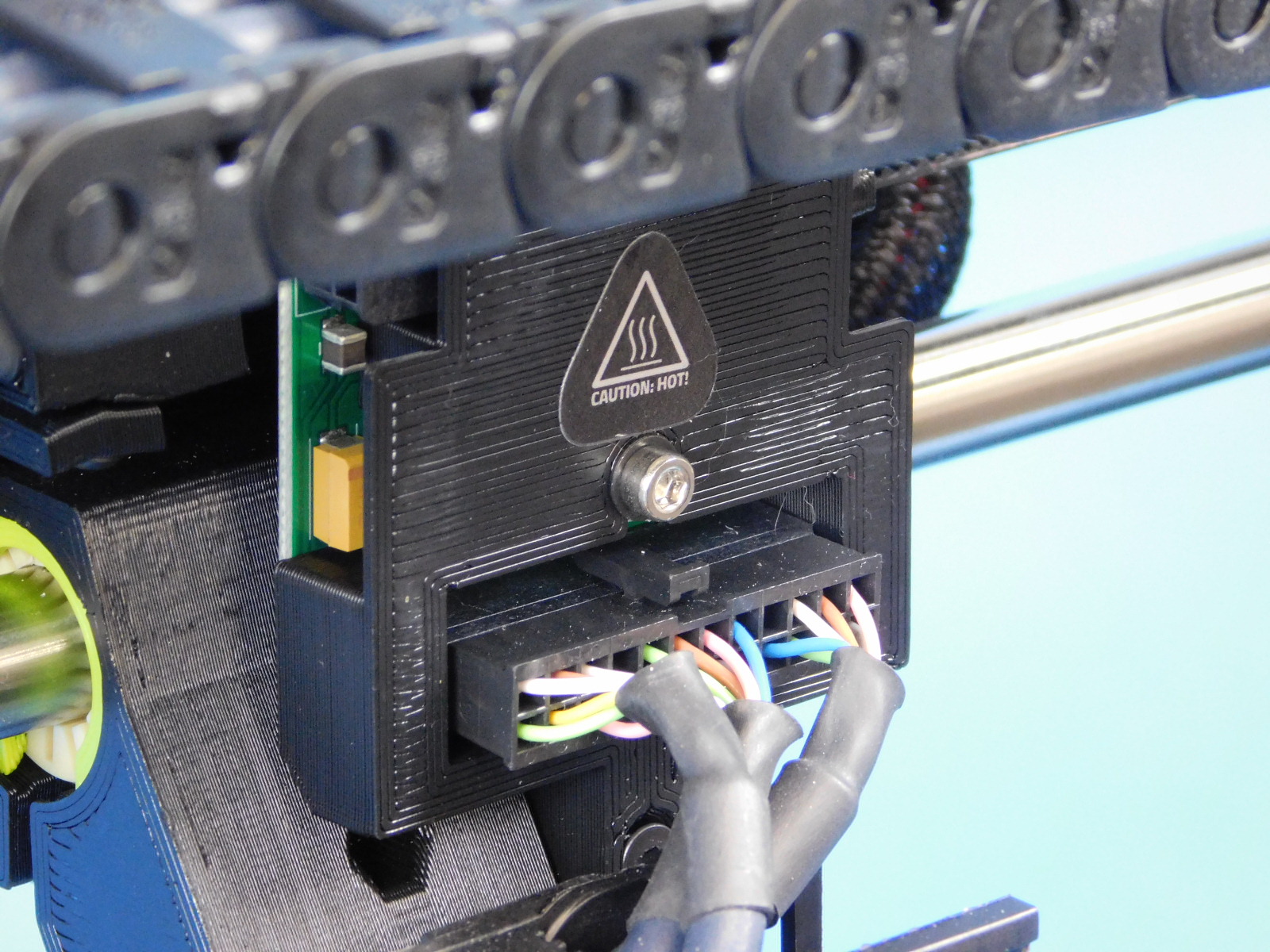
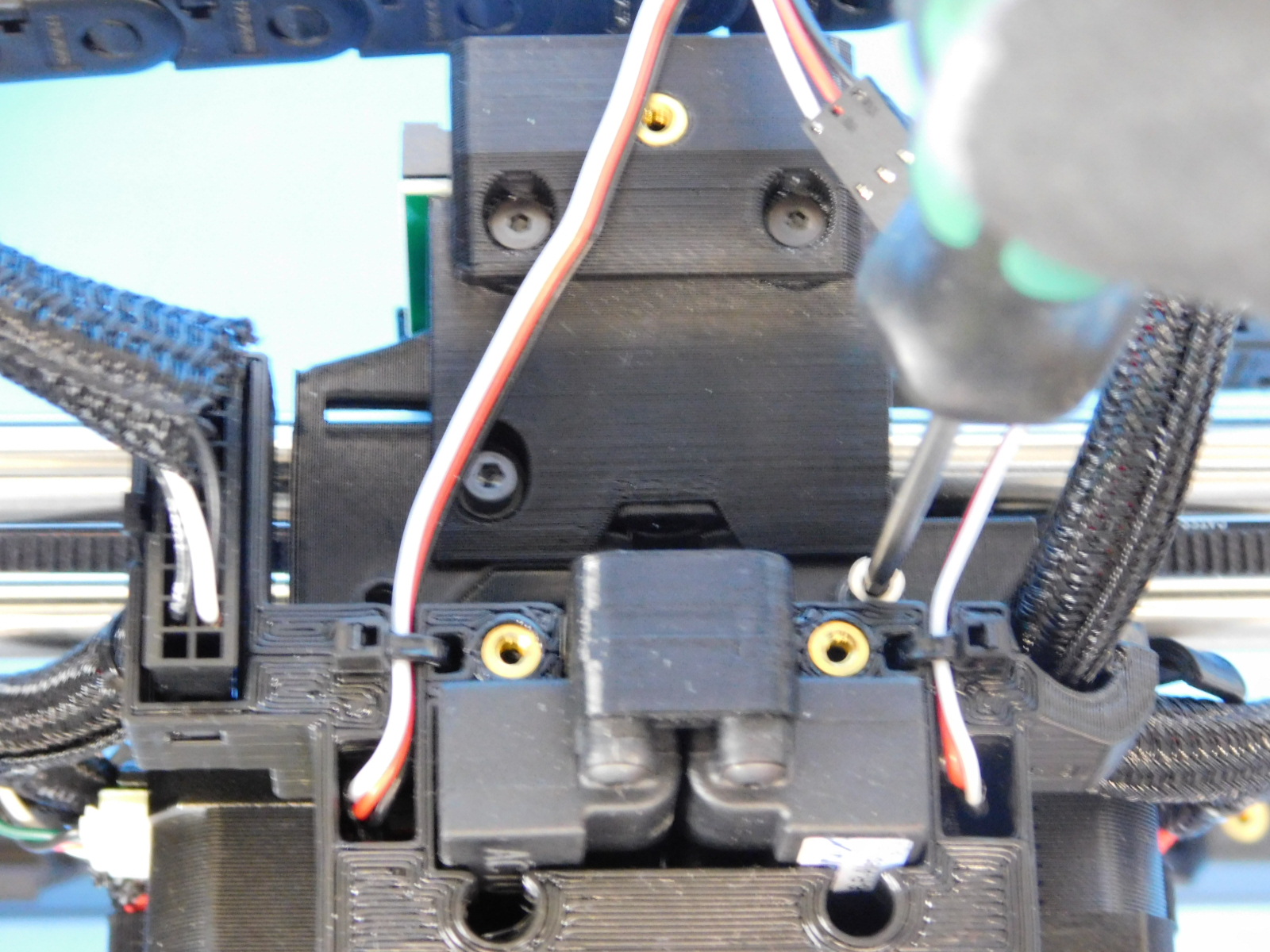
Obtain one Interface Board Cover w/ Inserts [PP-IS0101]
Place 2x- Caution Hot! Stickers [DC-LB0154] on the interface board cover (rear of the tool head) as pictured. One near the top, one just above the bottom connector of the interface board.
Press it into place over the Dual Interface Board [PC-BD0111] and secure at the bottom using 1x- M3x25 FHCS [HD-BT0206] and at the top using 2x- M3x6 FHCS [HD-BT0128].
Torque the top two fasteners to 3in*lbs
Torque the bottom fastener to 5in*lbs

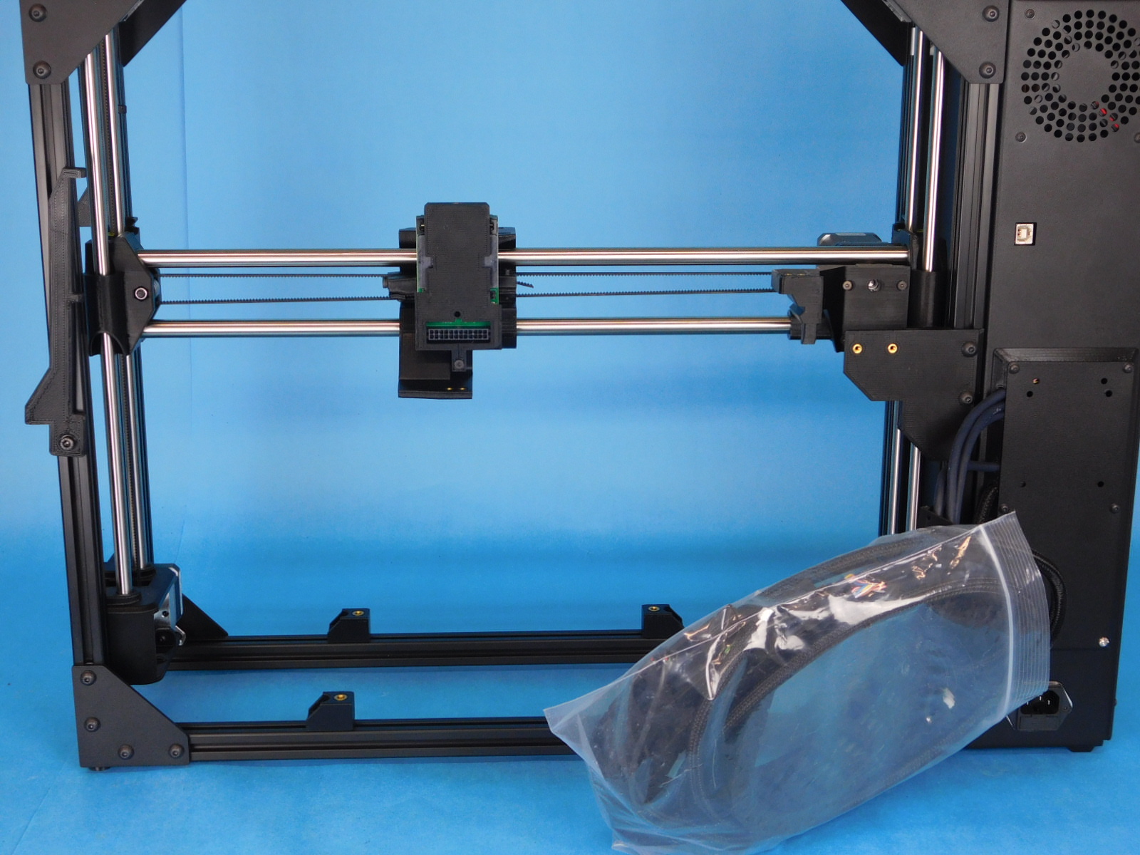
Pick up and rotate the assembly so that the back is facing you.
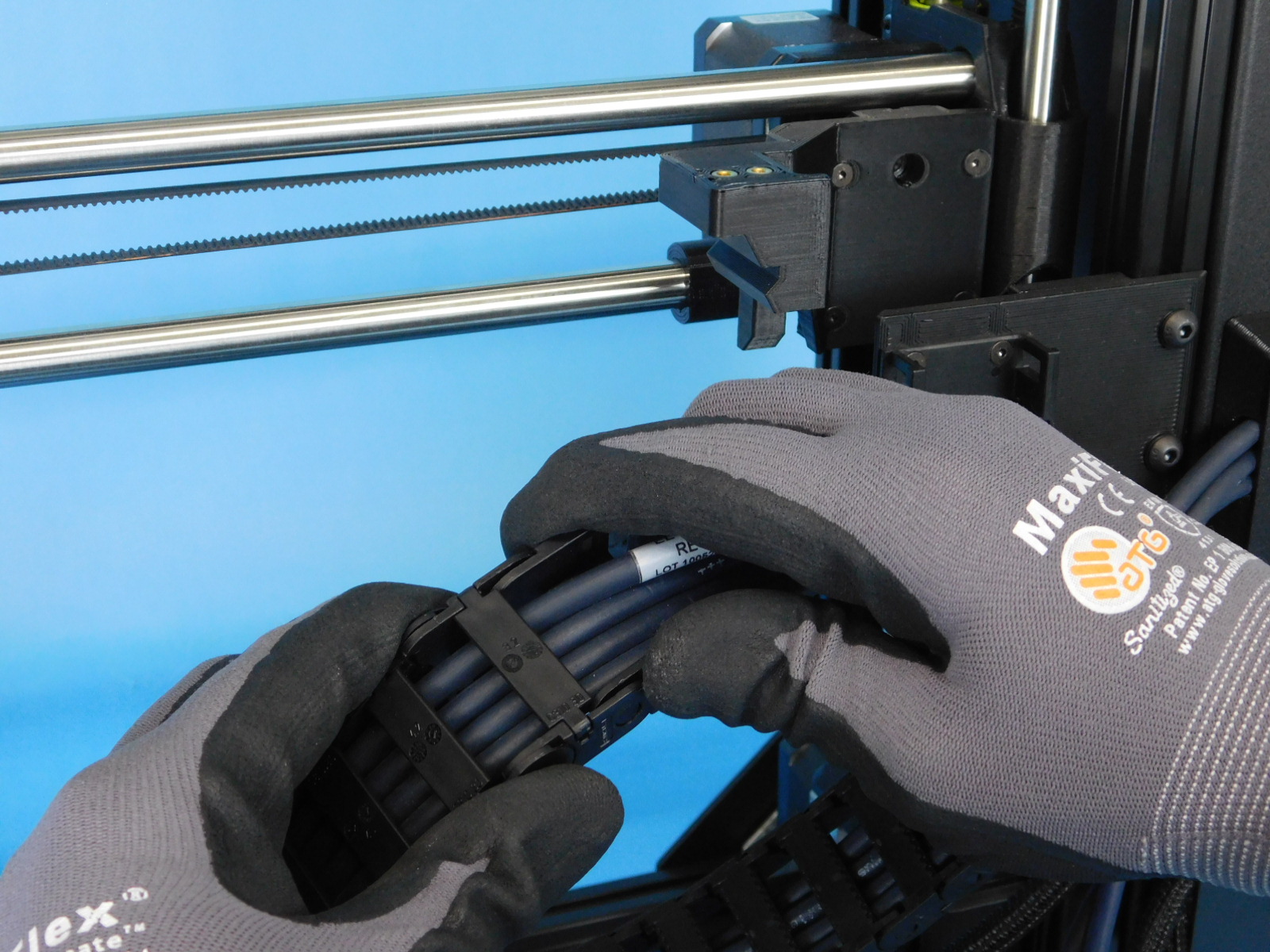
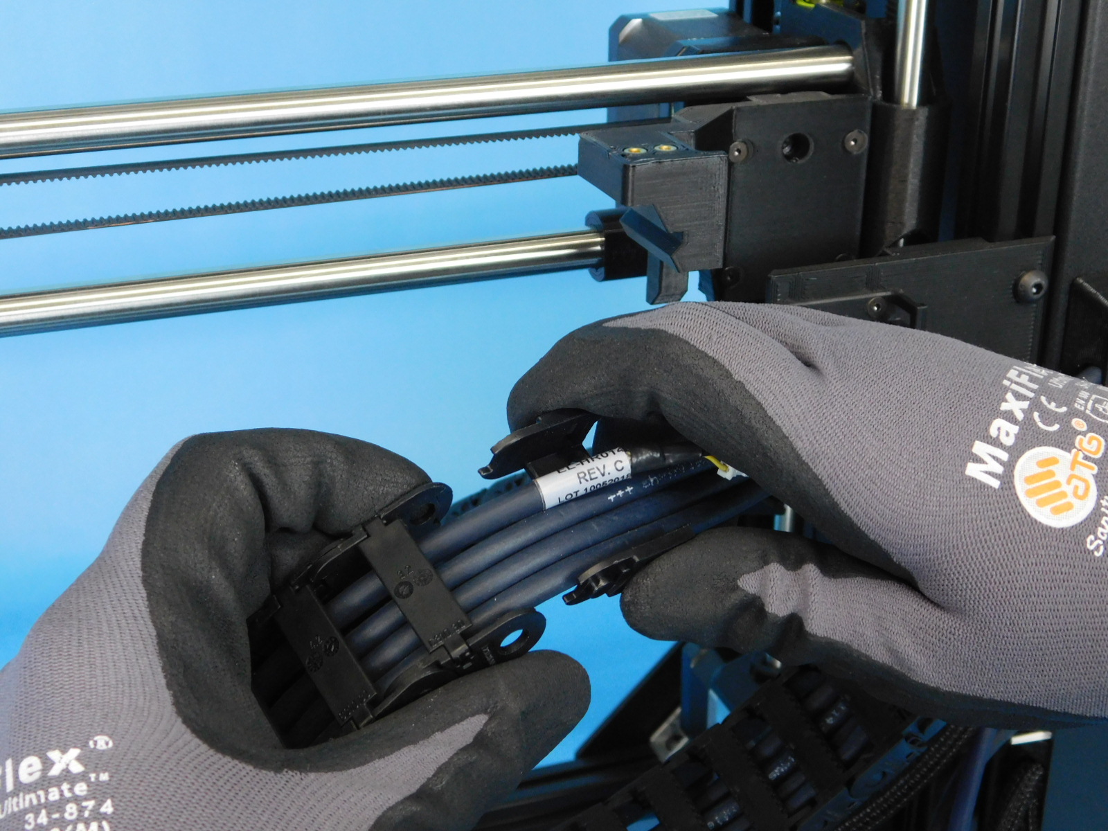
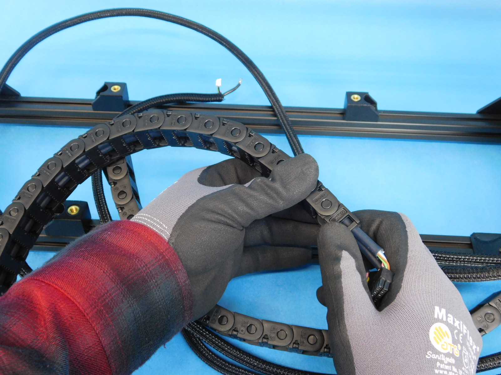
Remove the bag holding the cables.
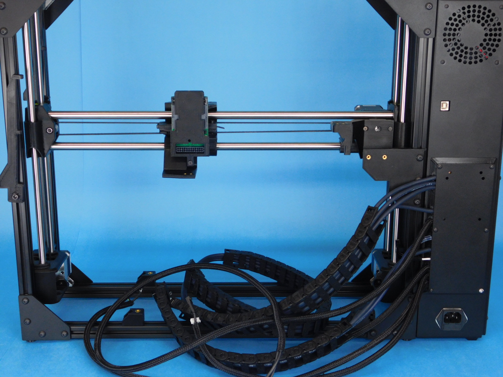
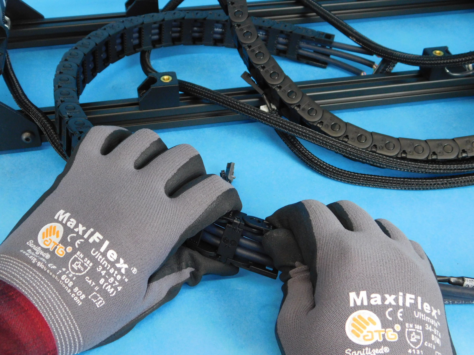
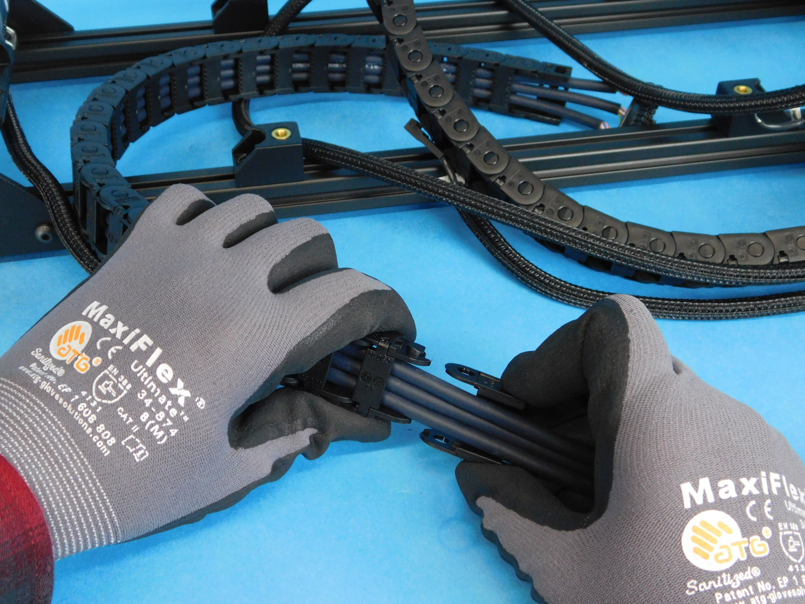
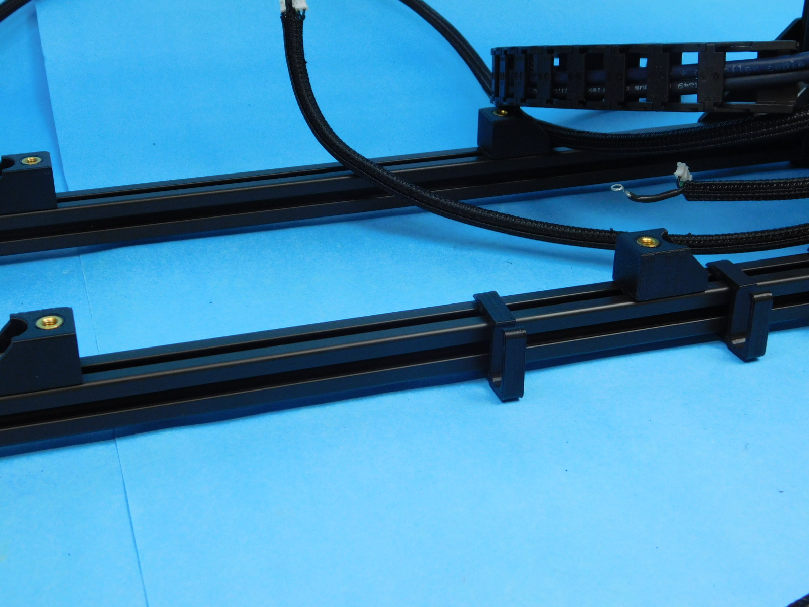
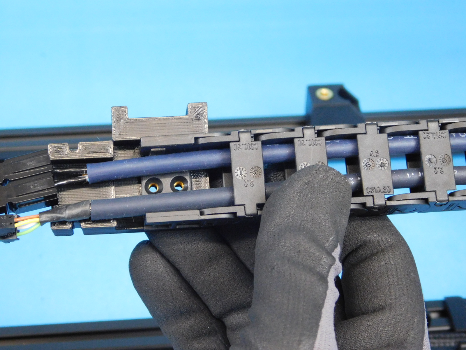
Begin with the long cables with 2 sections of cable chain that exit towards the top of the interconnect housing.
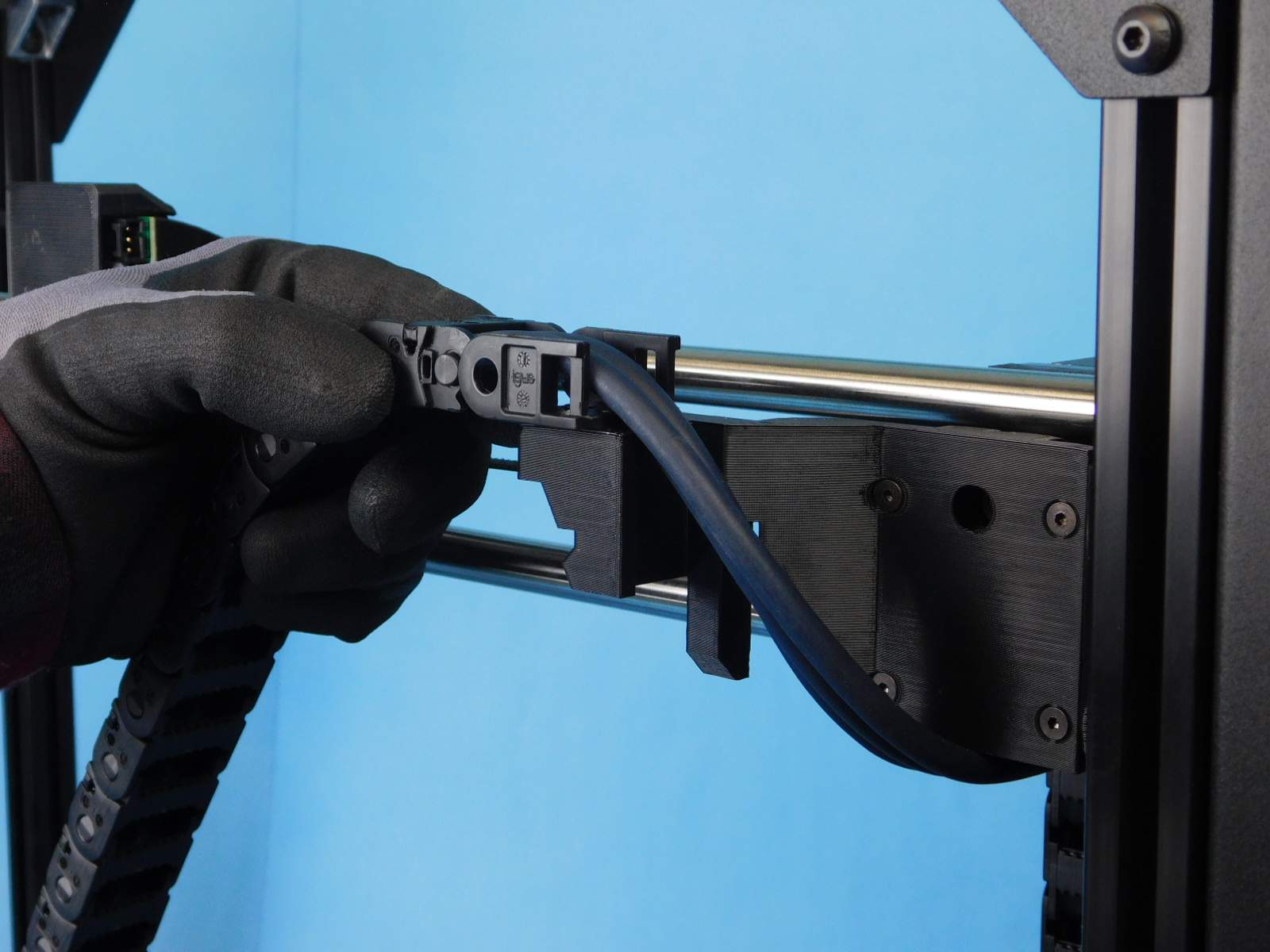
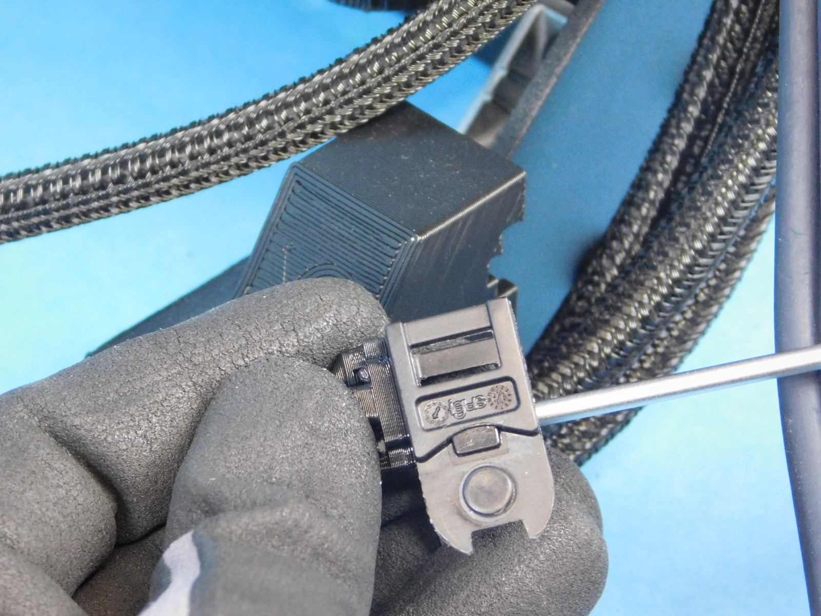
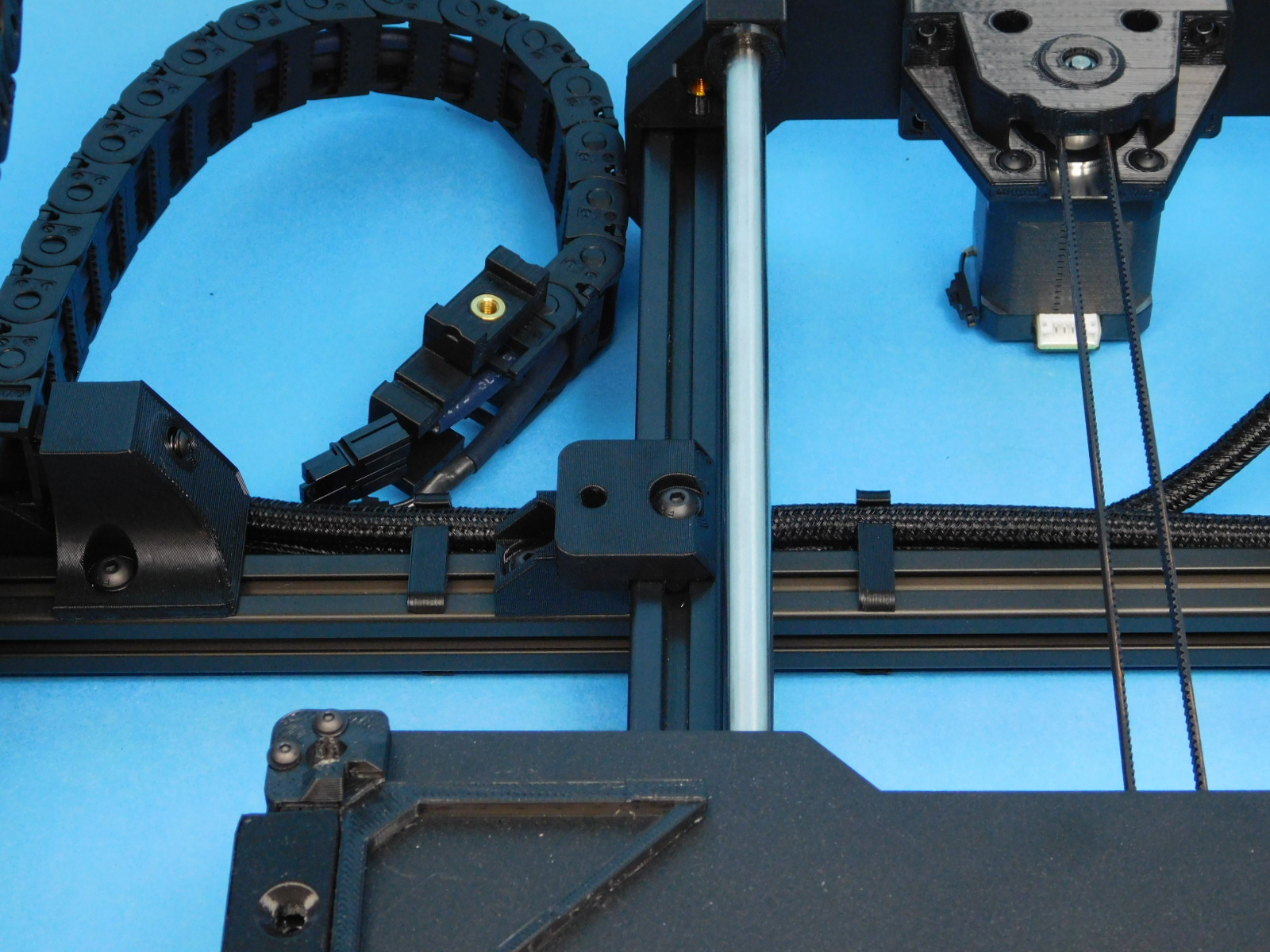
Remove the cable chain mount from the larger cable chain closest the control box and attach it to the Z-Chain Mount with the tabs facing down.
Use 2x- M3x6 FHCS [HD-BT0128], torque to 5in*lbs
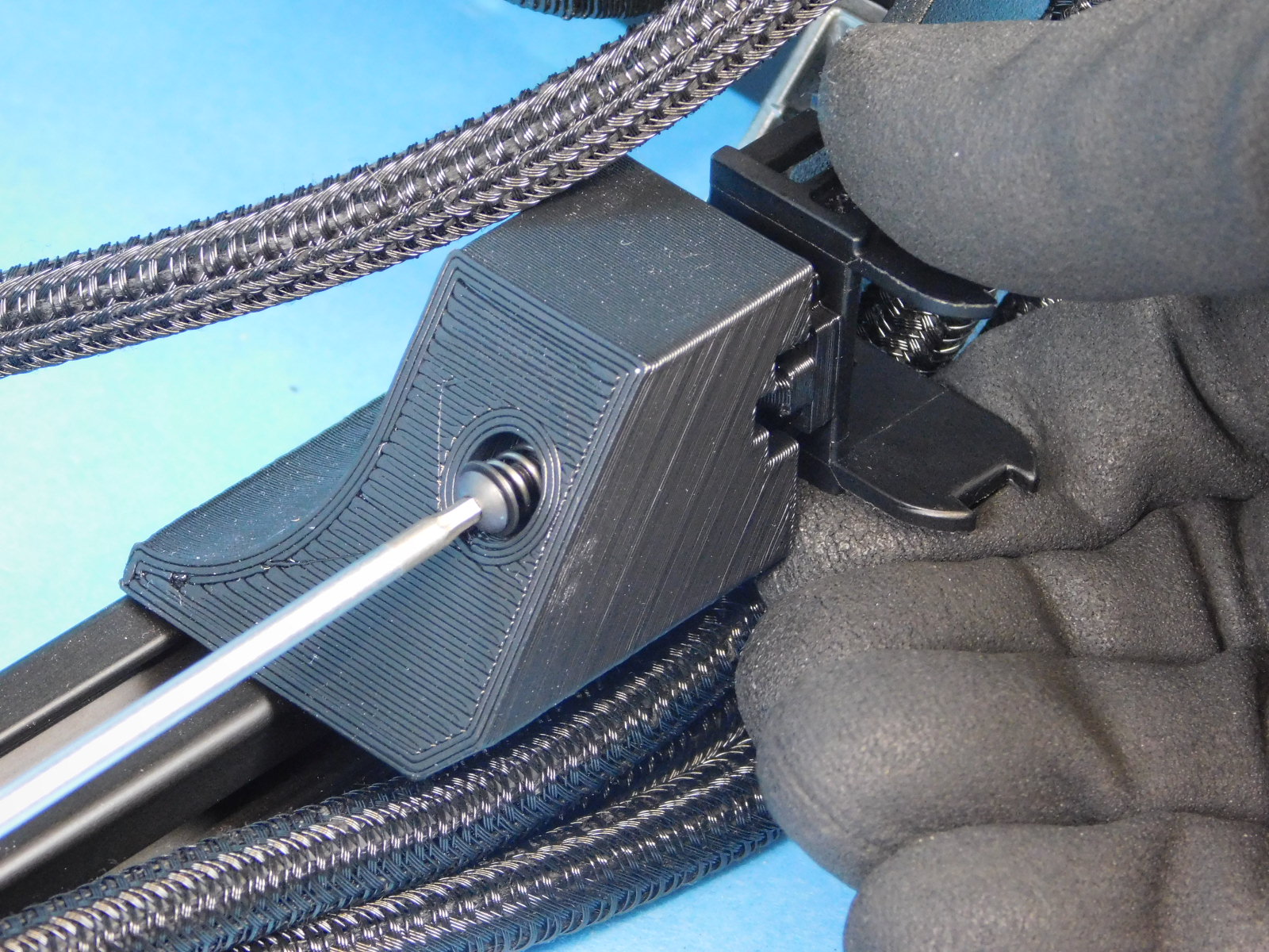
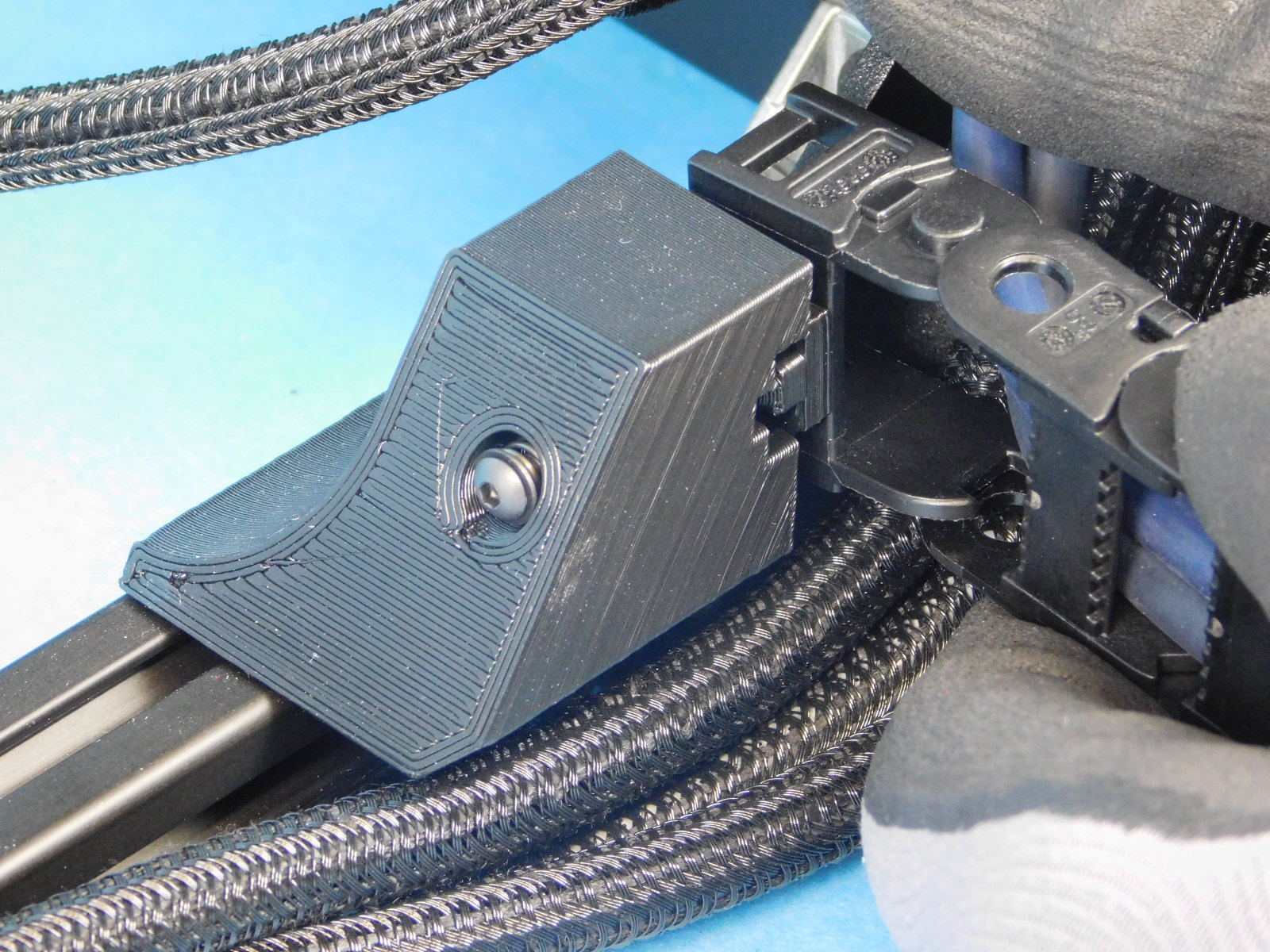
Remove the cable chain mount from the other end of the large cable chain and attach it to the front of the X-End Motor below the X Motor with the tabs facing down.
Again, use 2x- M3x6 FHCS [HD-BT0128], torque to 5in*lbs
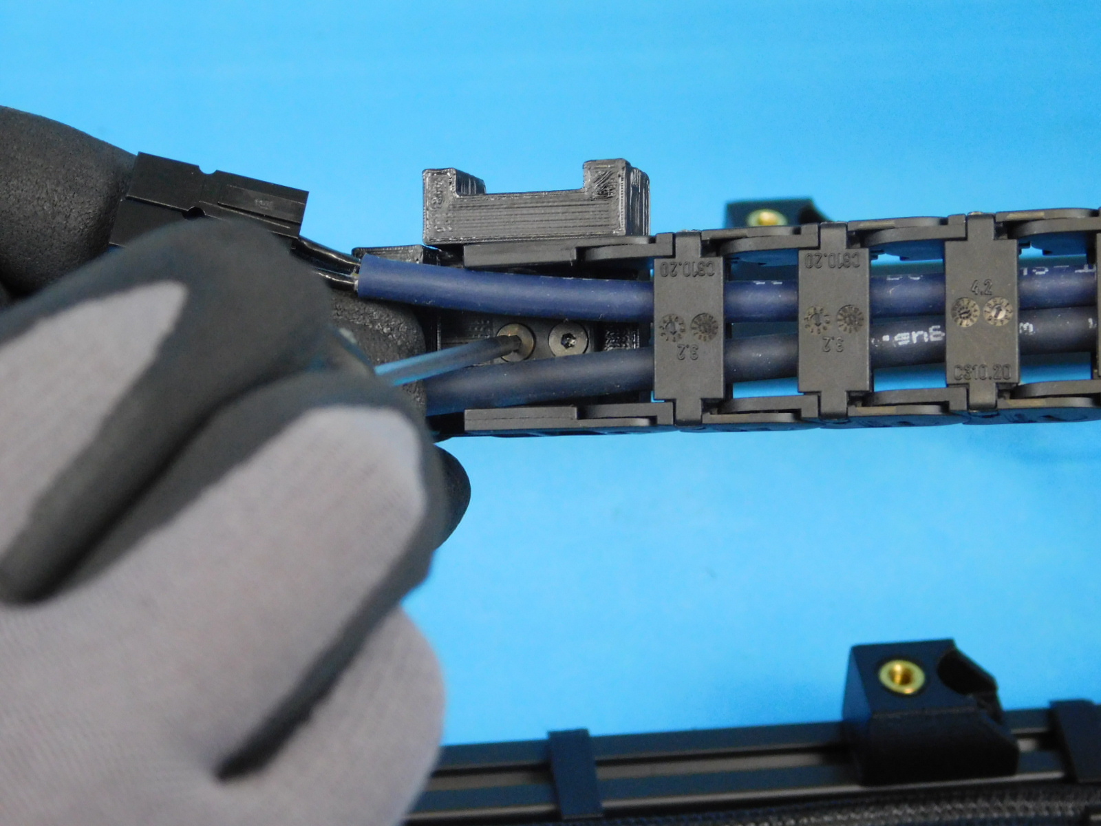
Remove the cable chain mount closest the control box on the smaller cable chain on the same harness and attach it to the top of the X-Motor Chain Mount with the tabs facing the X-Idler End.
Again, use 2x- M3x6 FHCS [HD-BT0128], torque to 5in*lbs
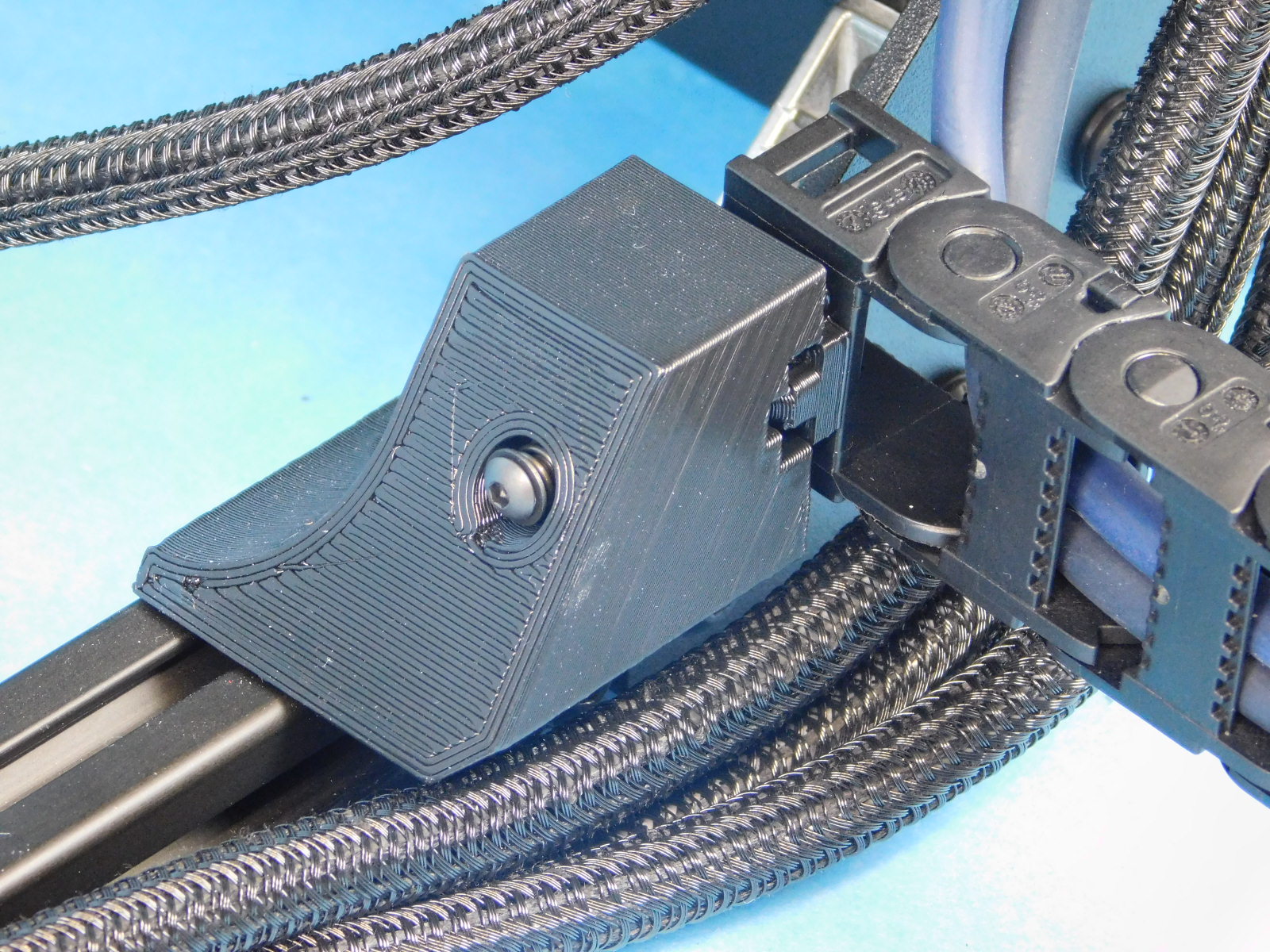
Remove the last chain mount from the harness and attach it to the X-Carriage at the rear with the tabs facing the X-Idler End.
Again, use 2x- M3x6 FHCS [HD-BT0128], torque to 5in*lbs


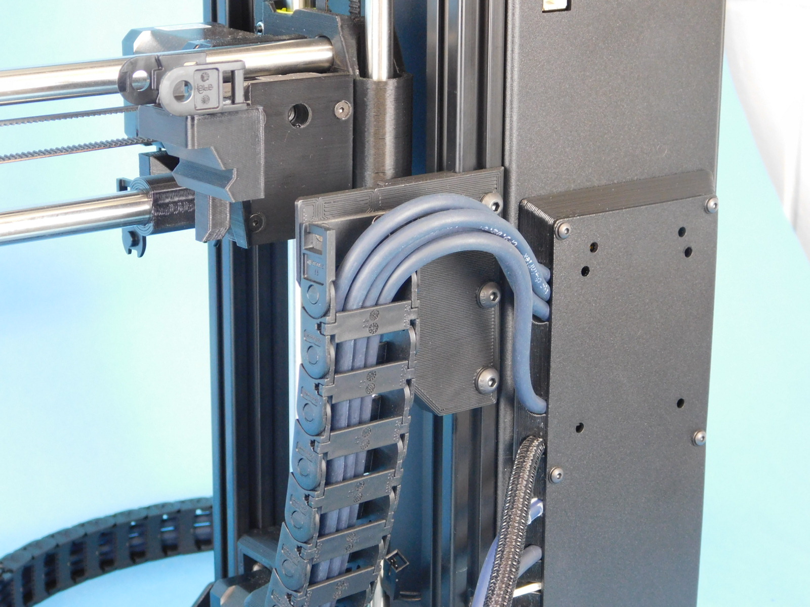
Attach the Z cable chain to the z cable chain mount as pictured.
It should bend in towards the frame.
Bend the cables back at the other end and attach the cable chain to the mount as pictured.
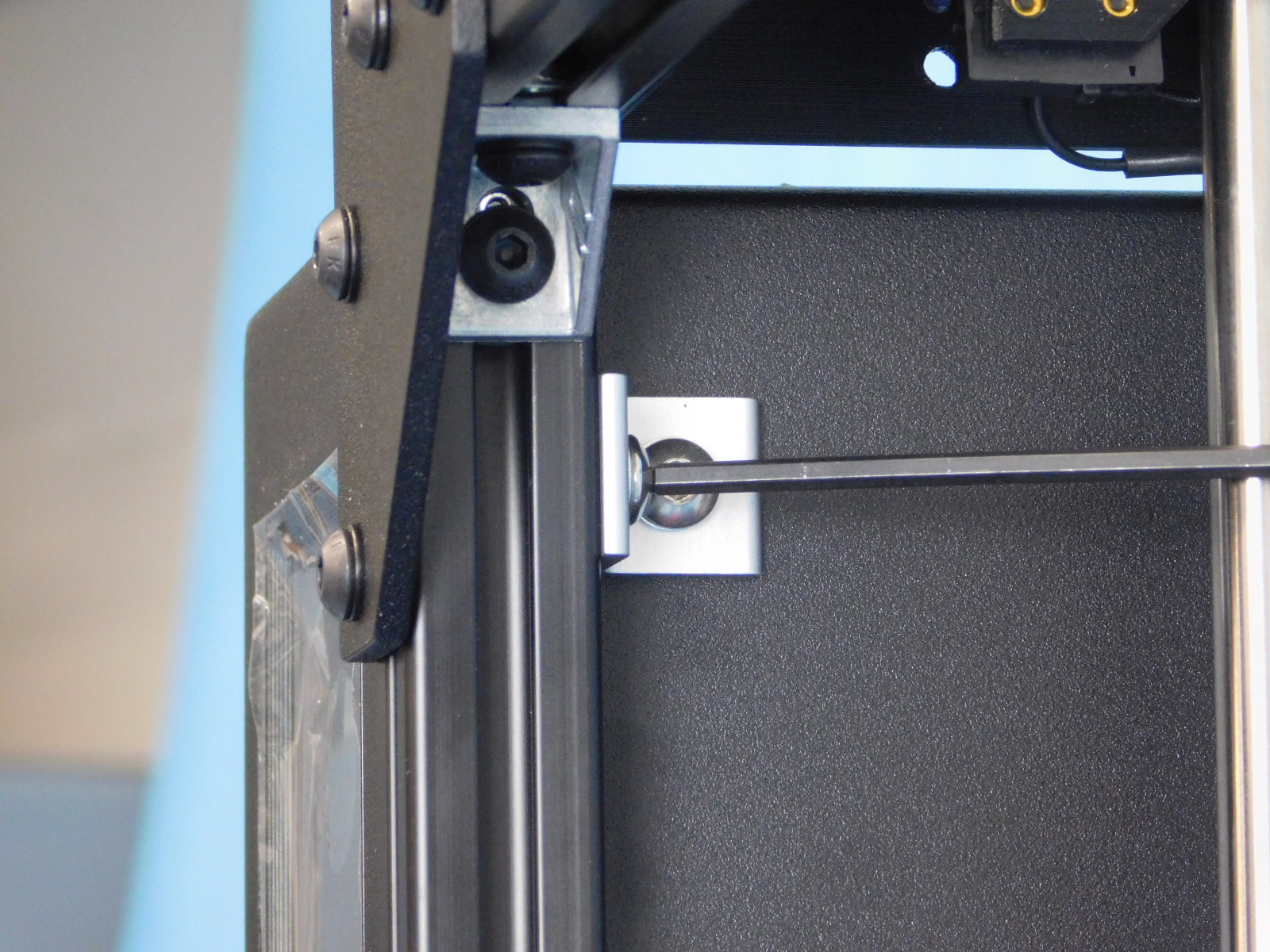
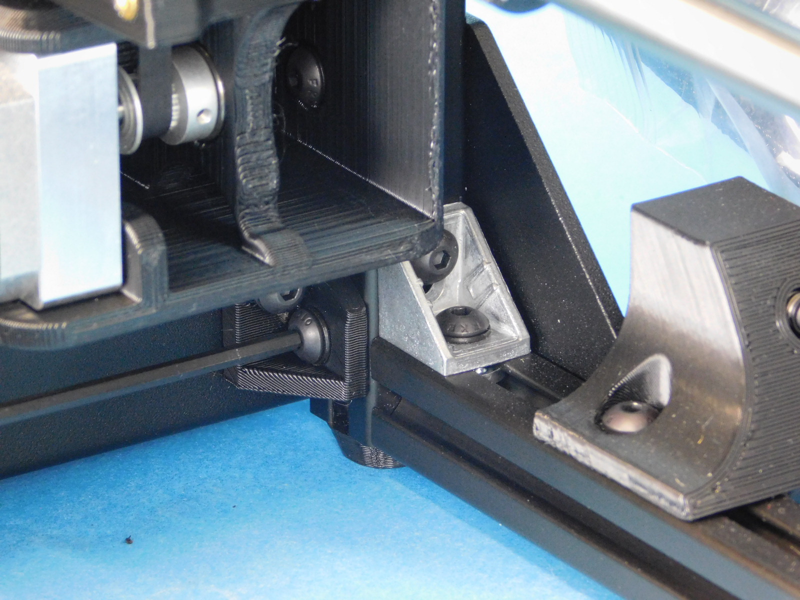
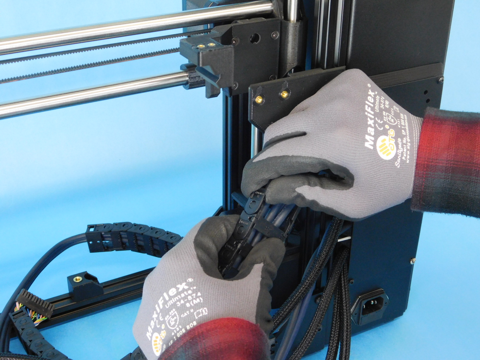
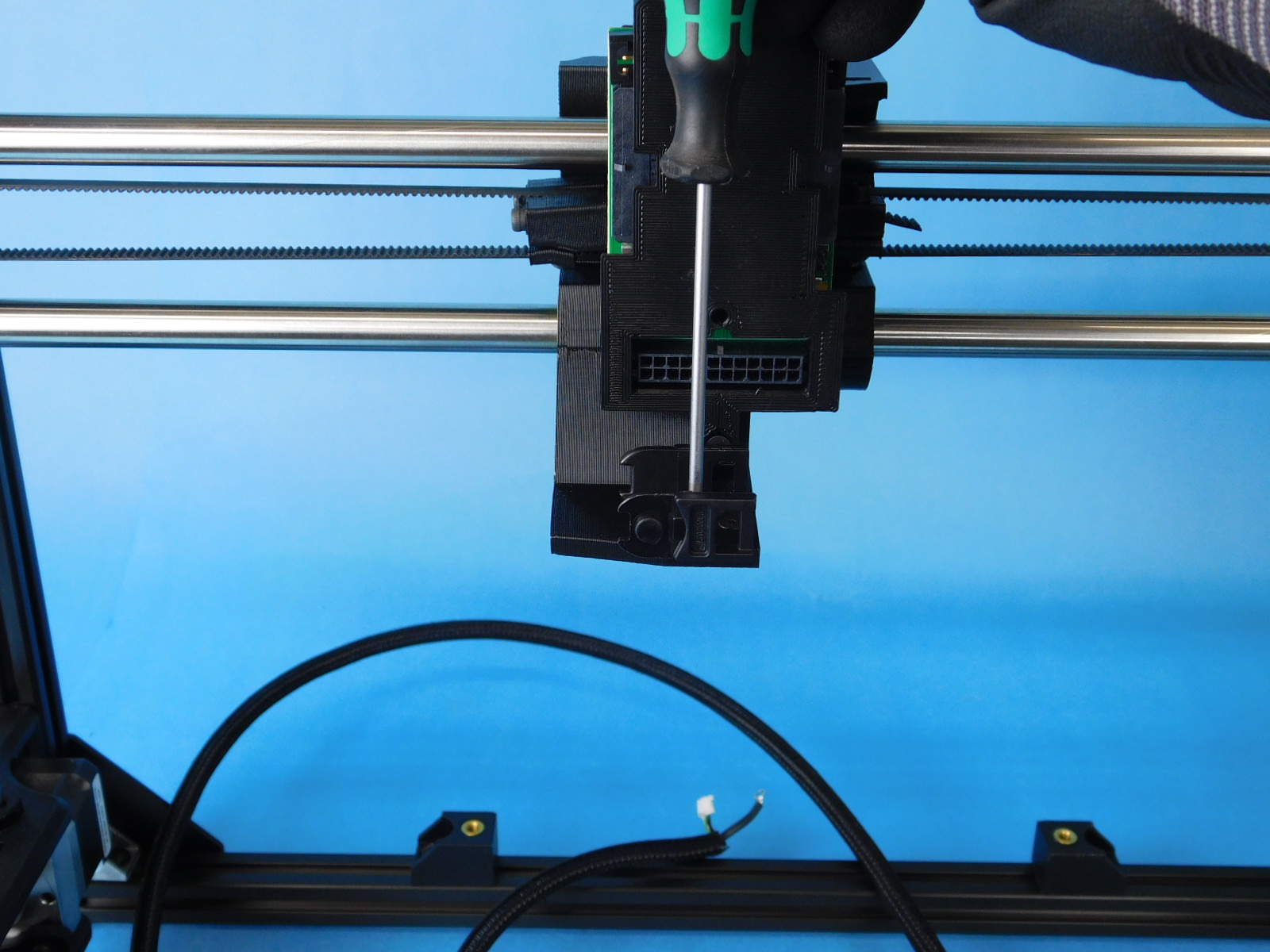
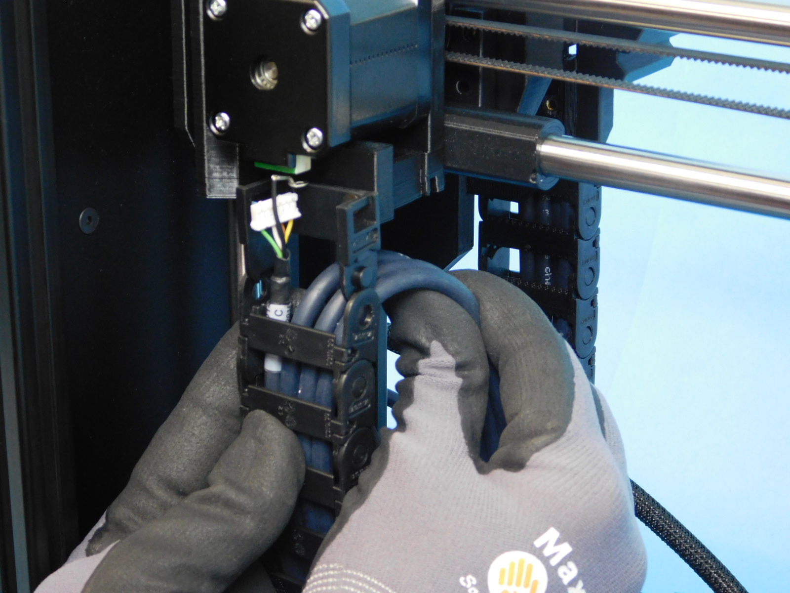
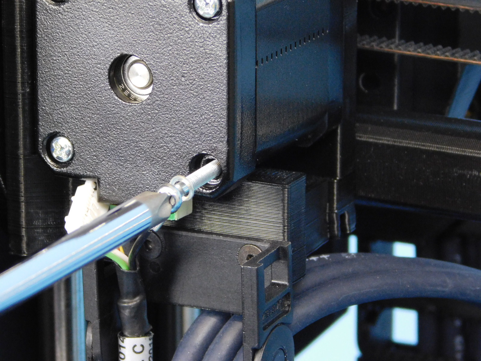
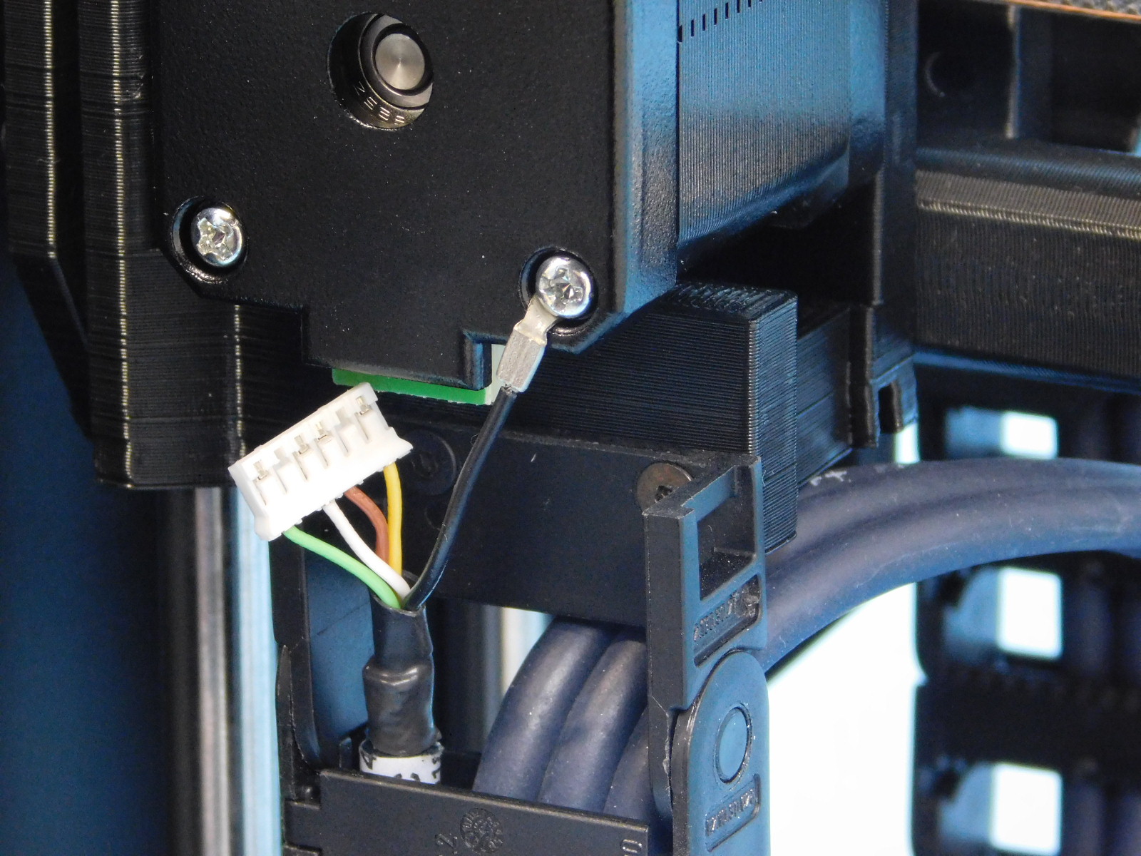
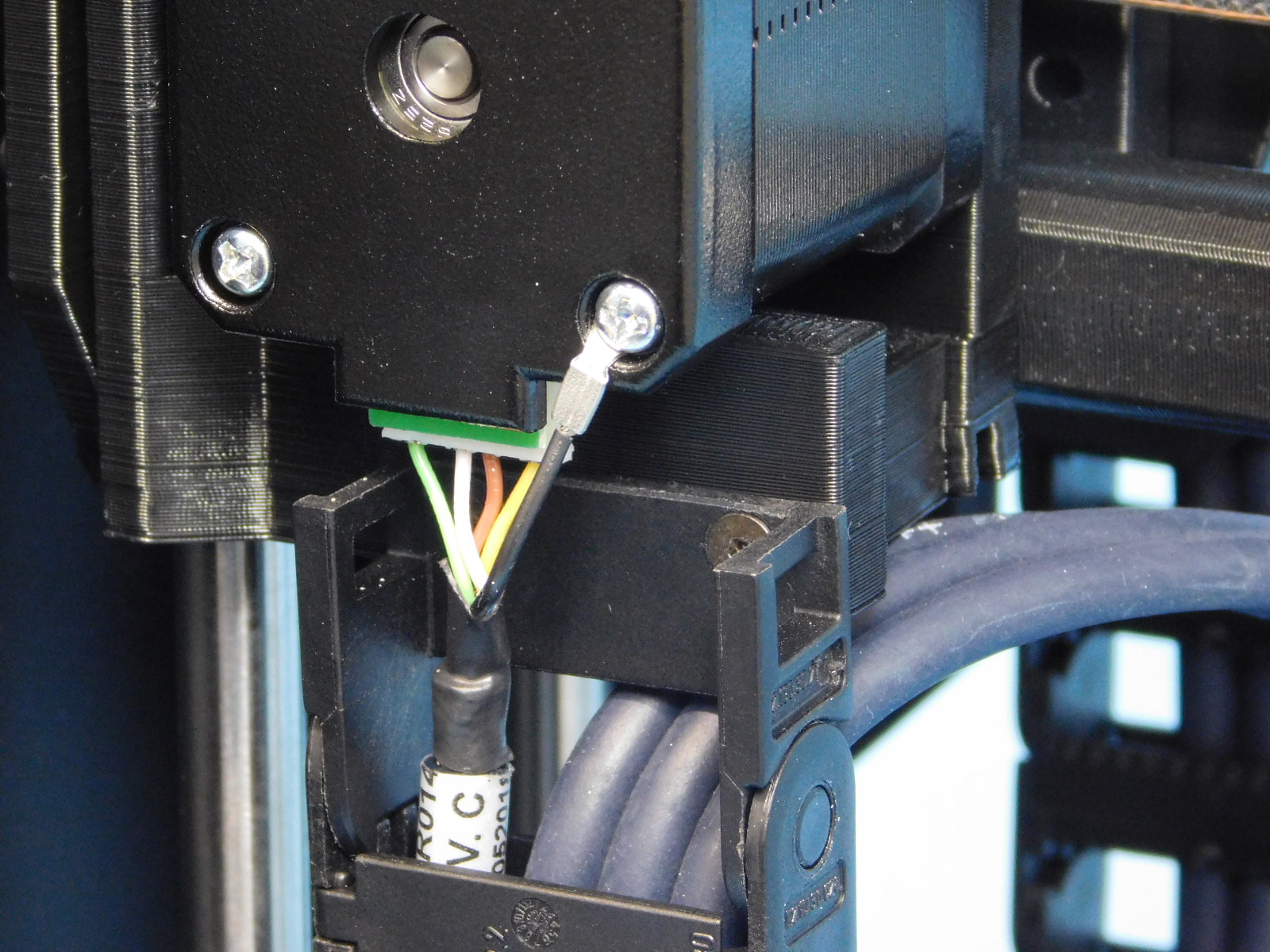
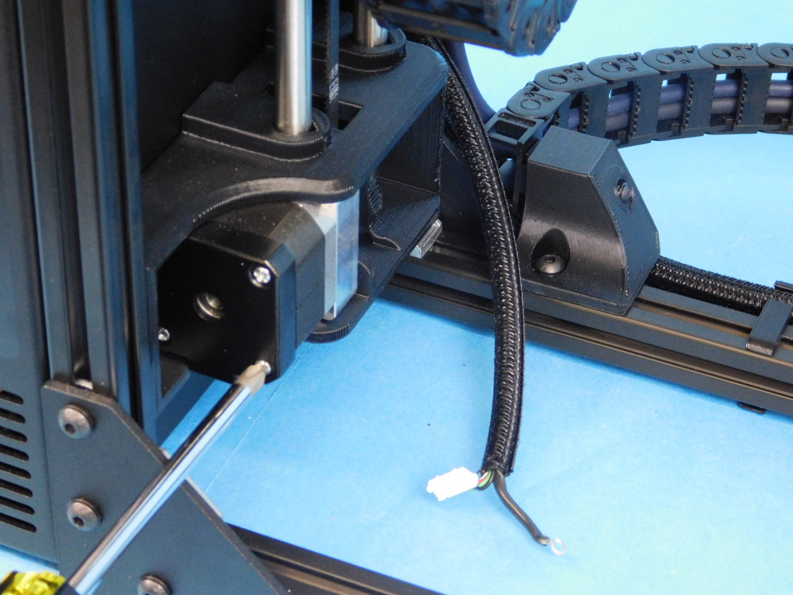
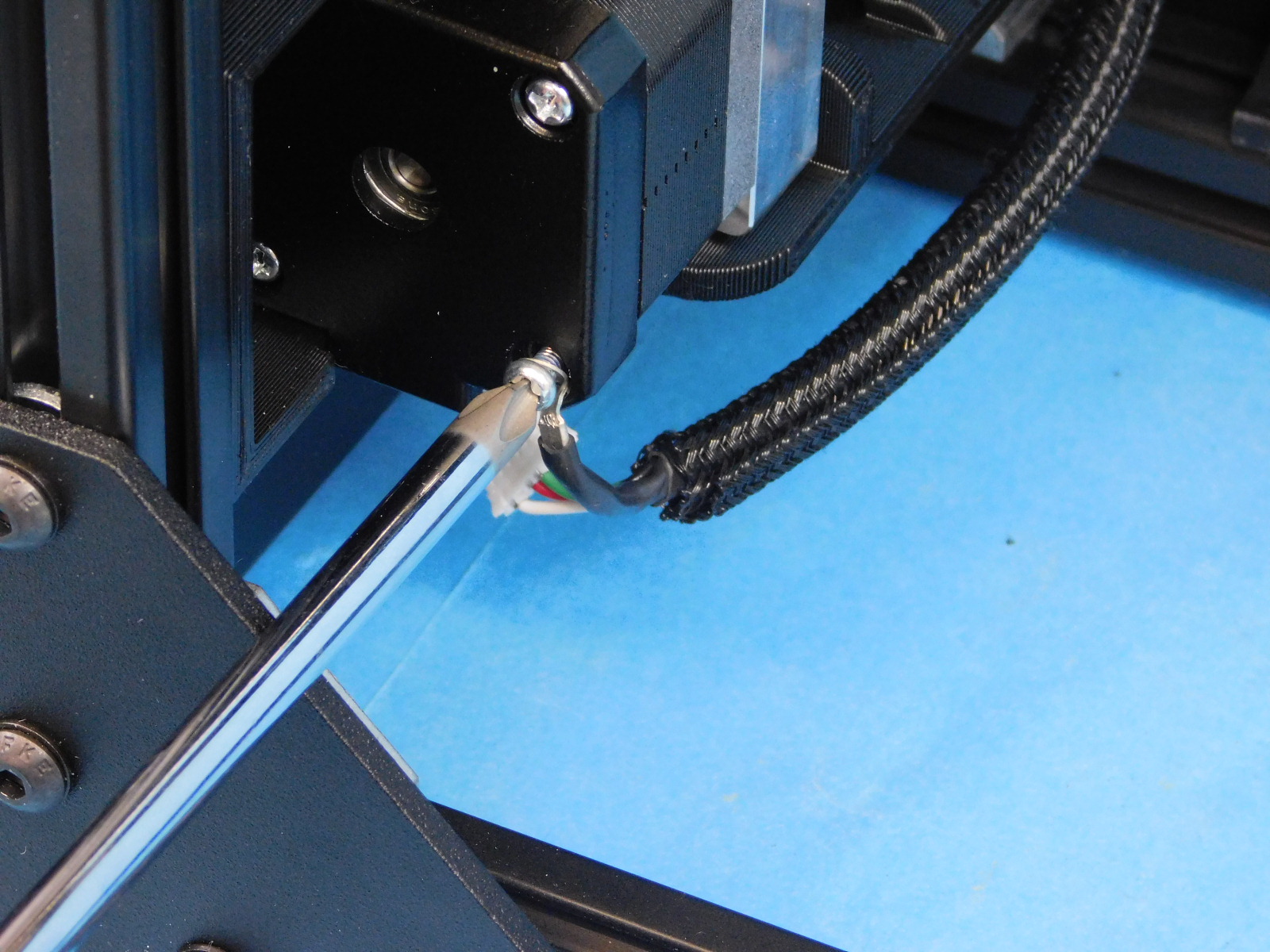
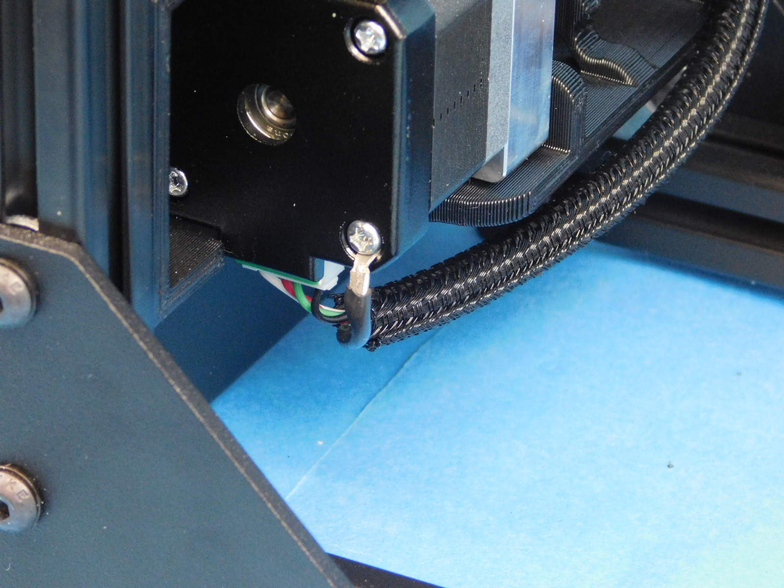
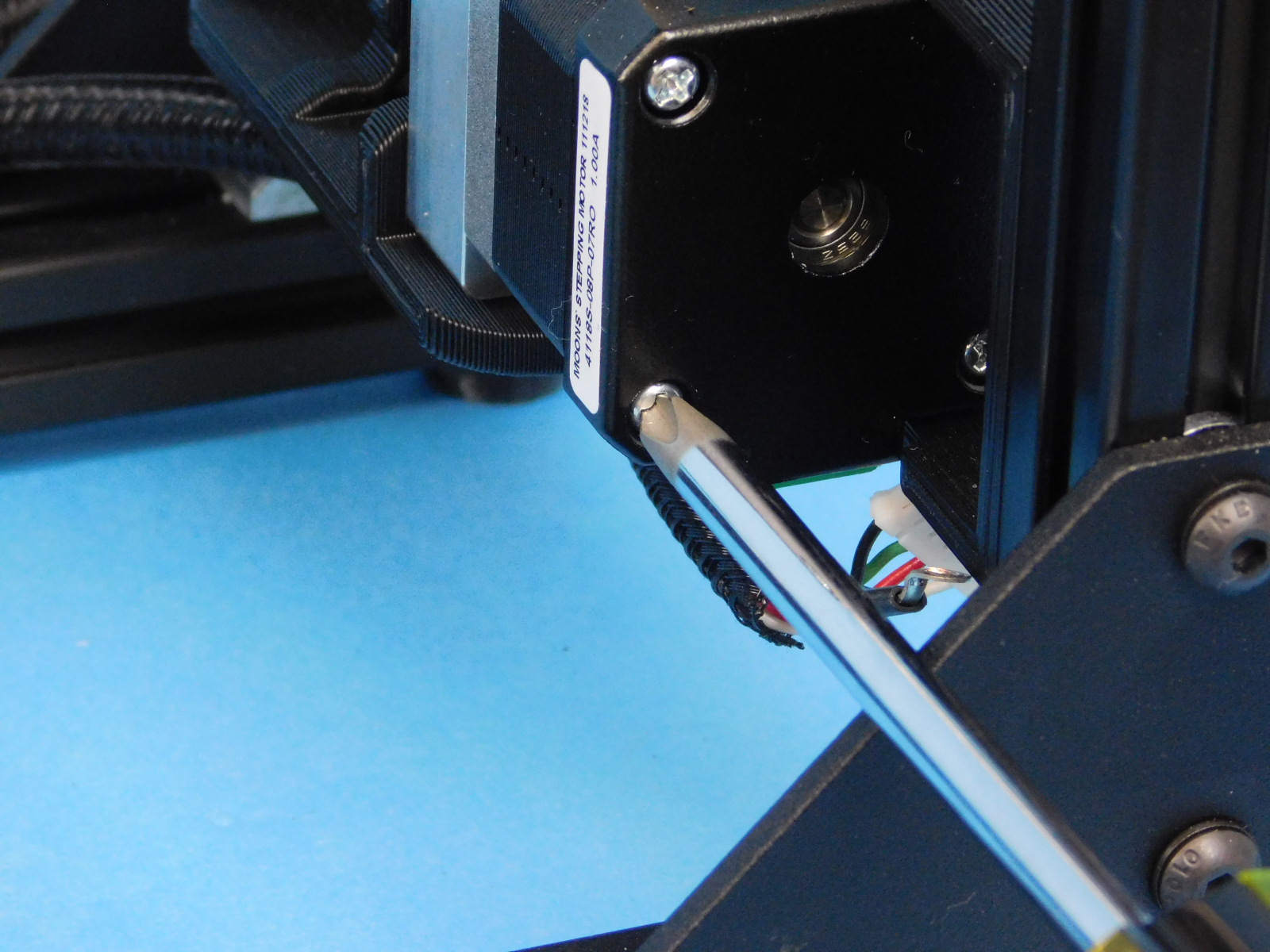
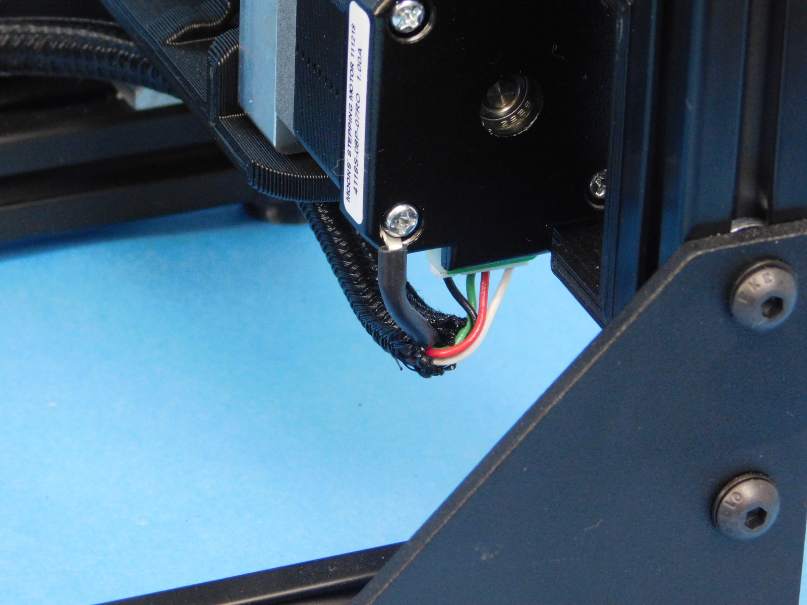
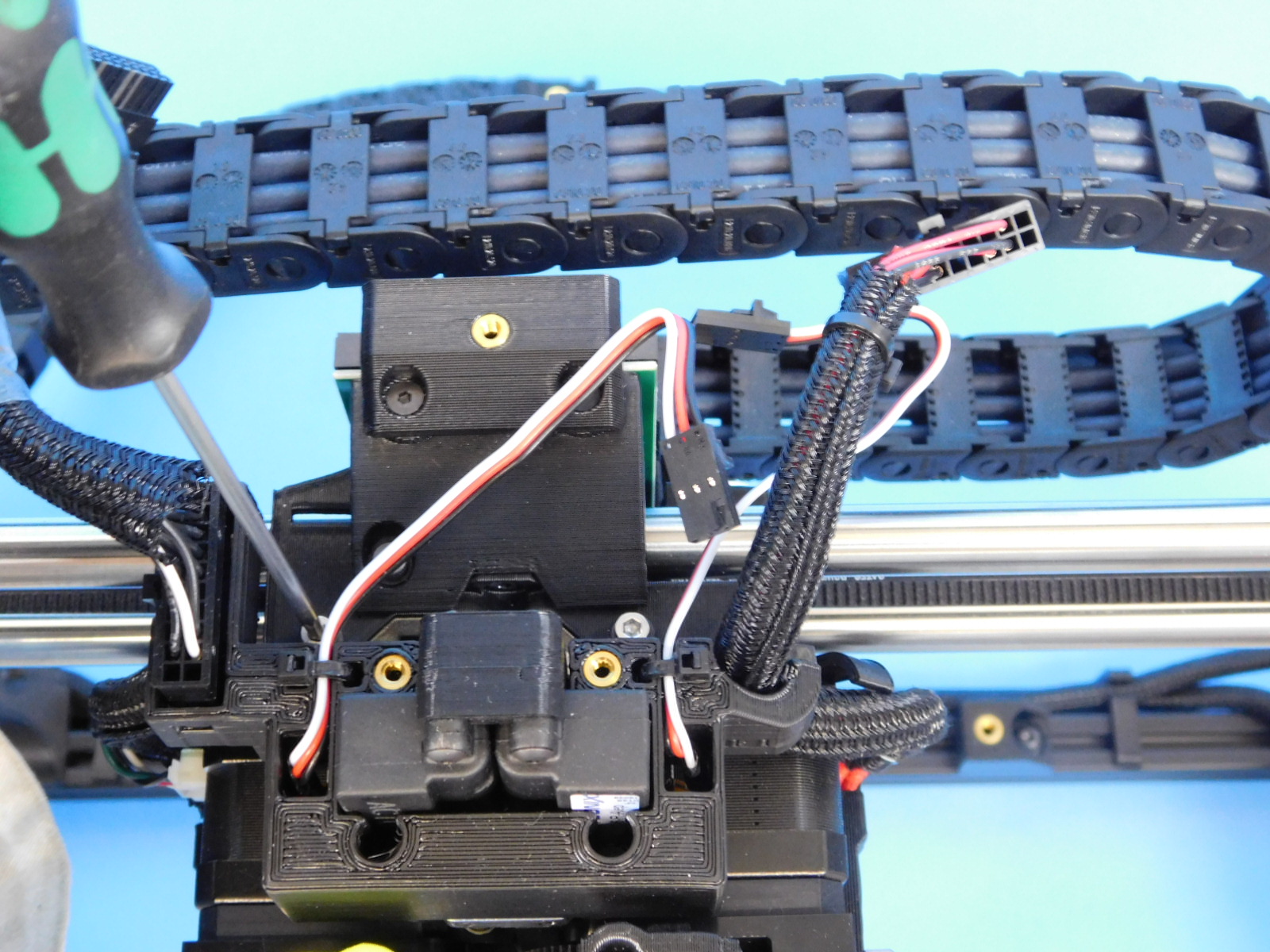
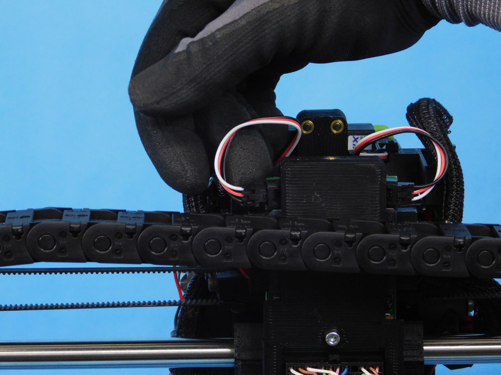
Remove the highlighted fastener with a P2 Phillips driver and attach the X Motor Ground terminal ring to it, retighten securely.
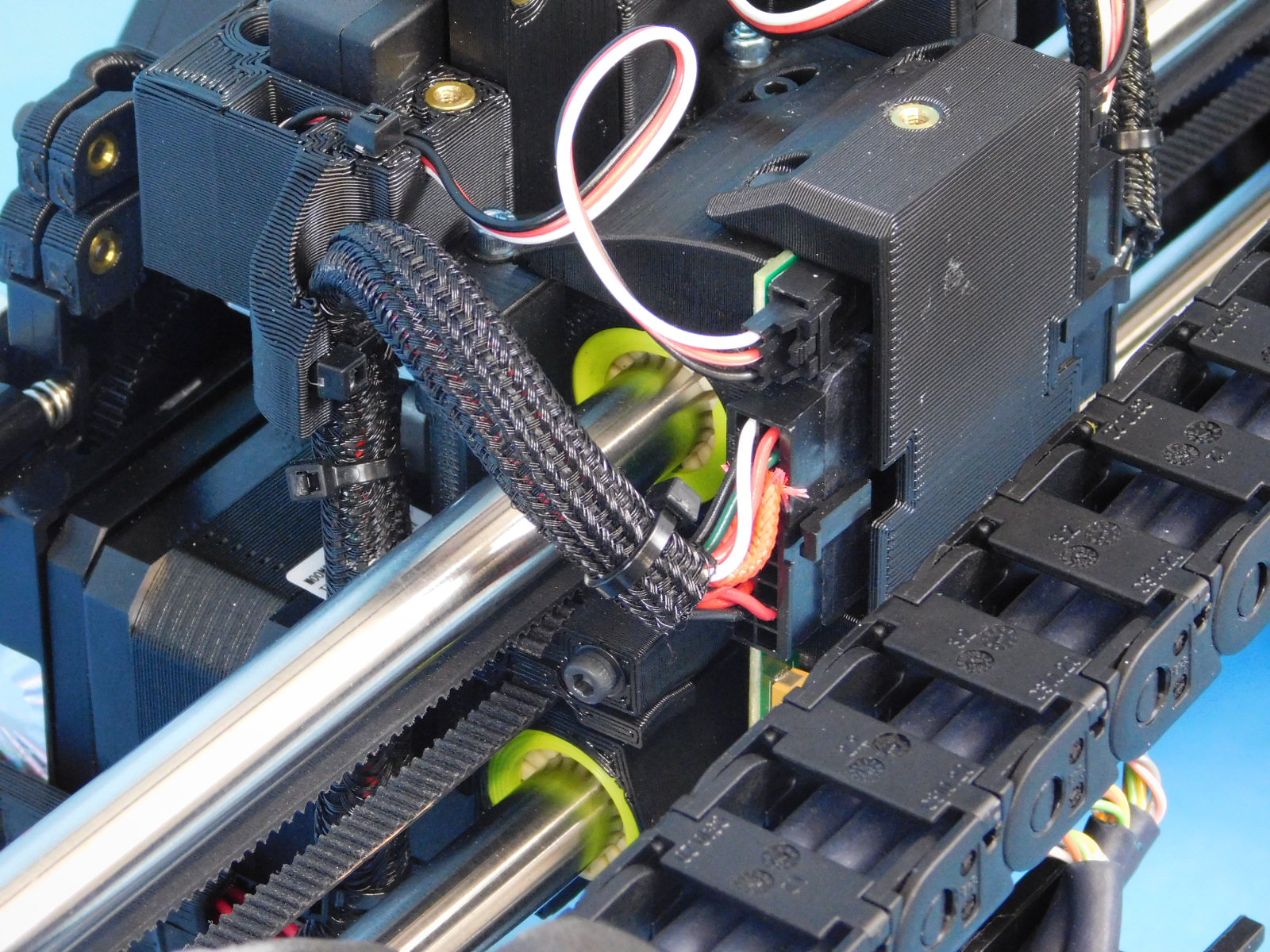
Plug the JST connector at that location into the X-Axis drive motor.
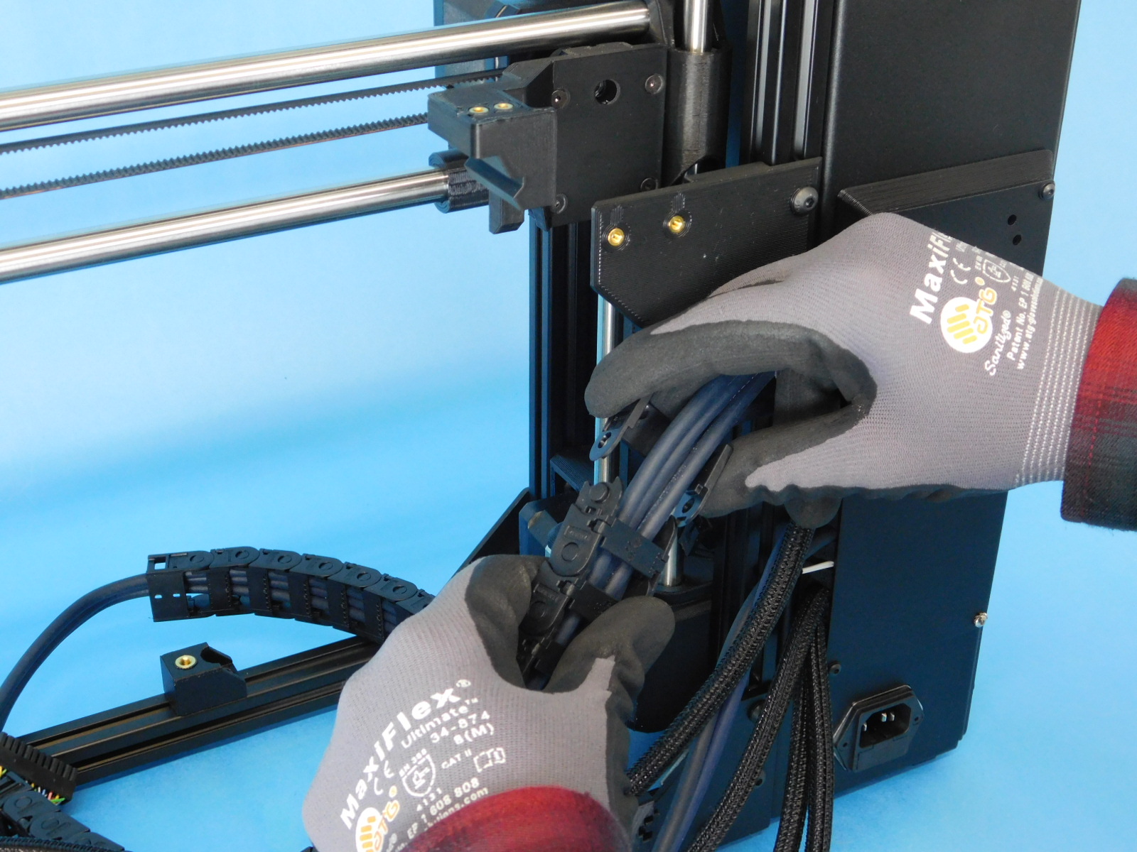
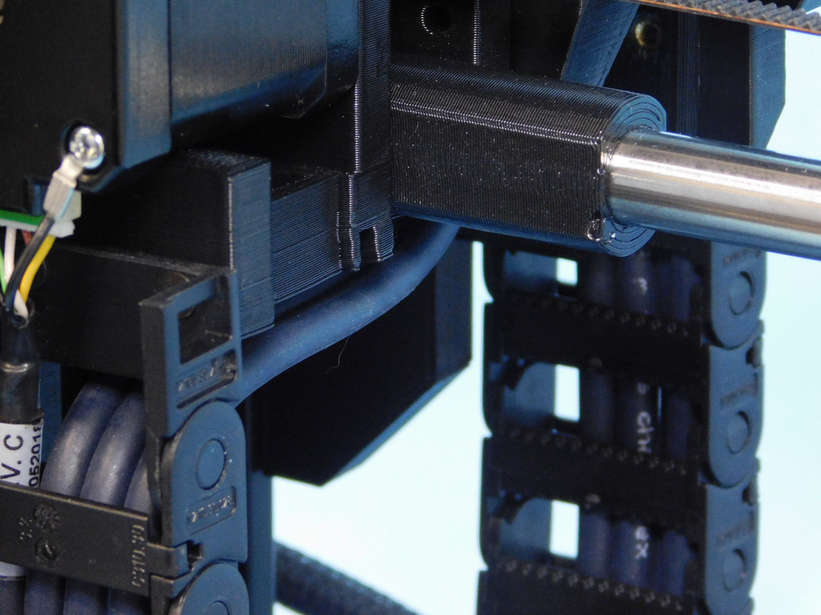
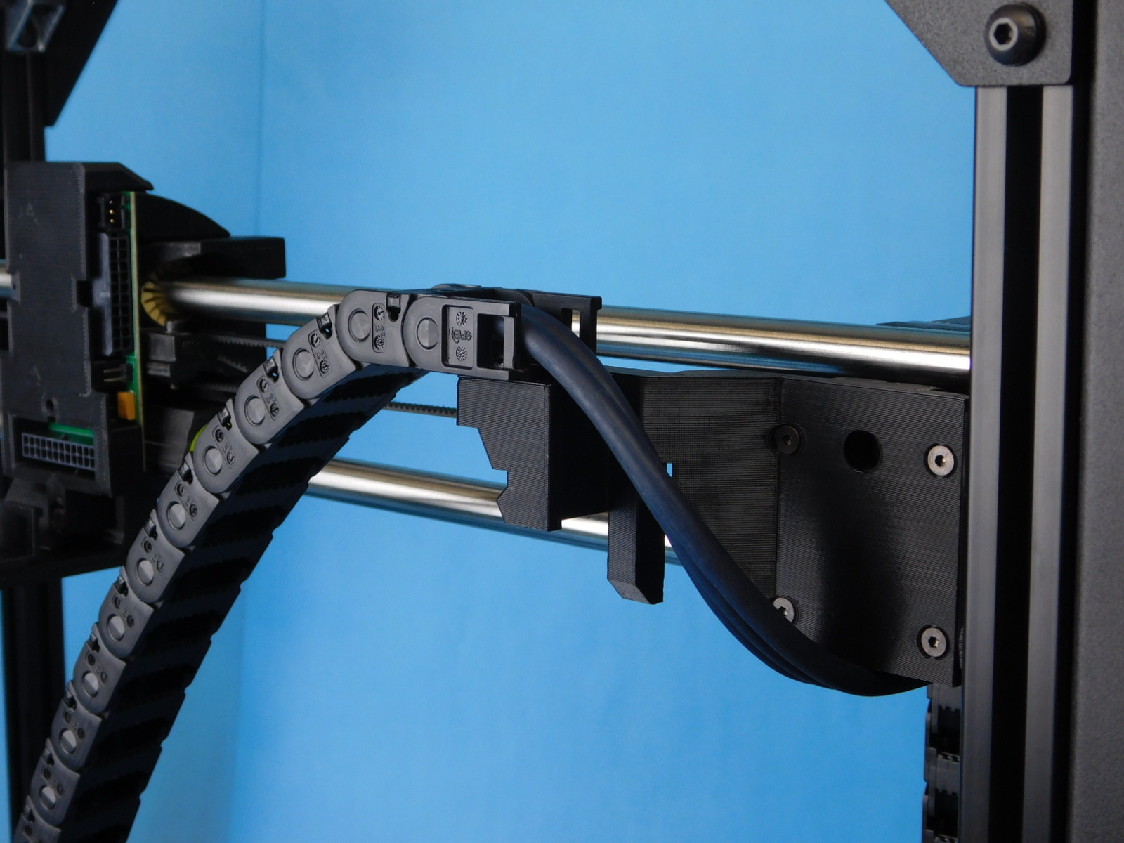
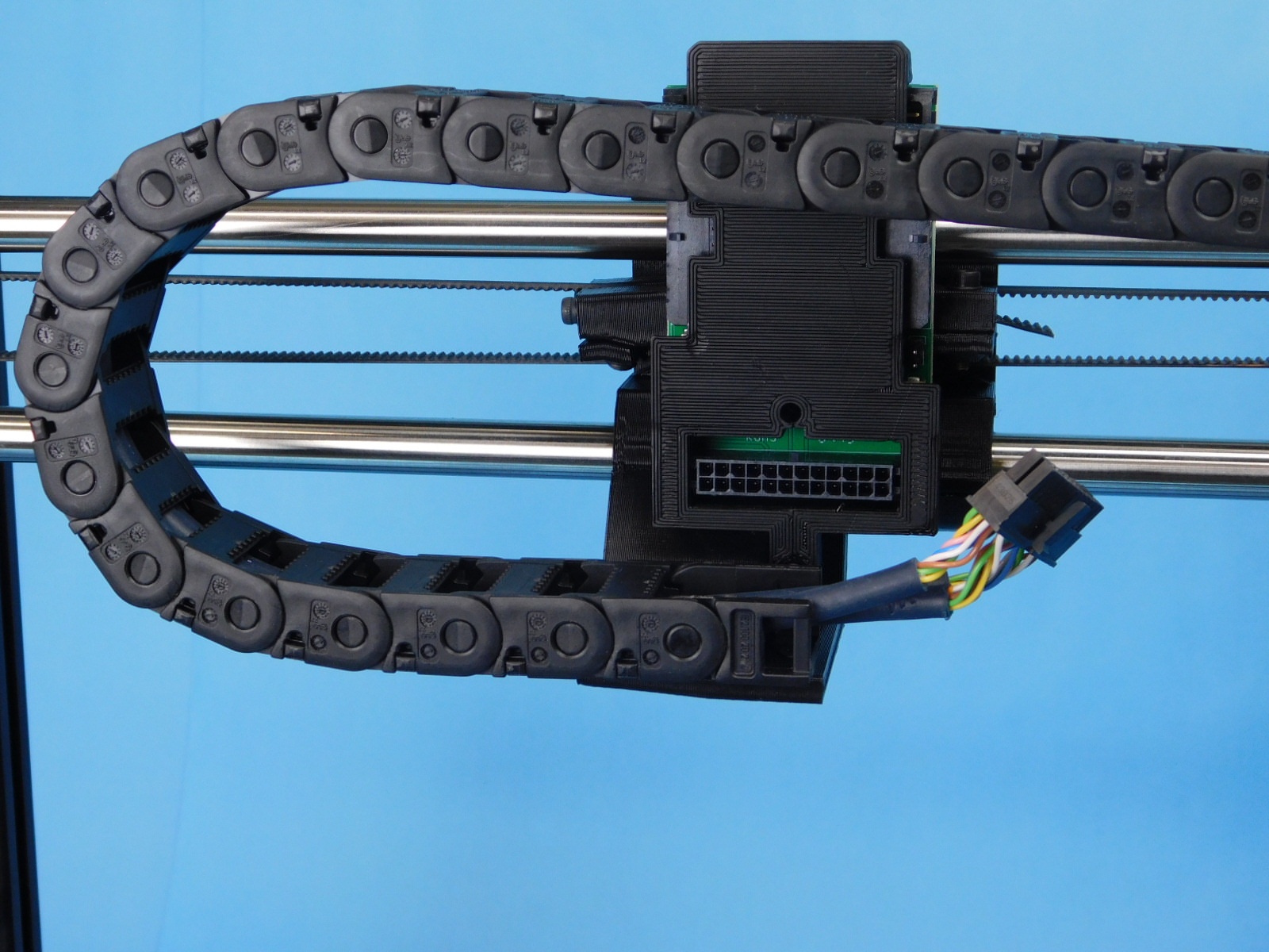
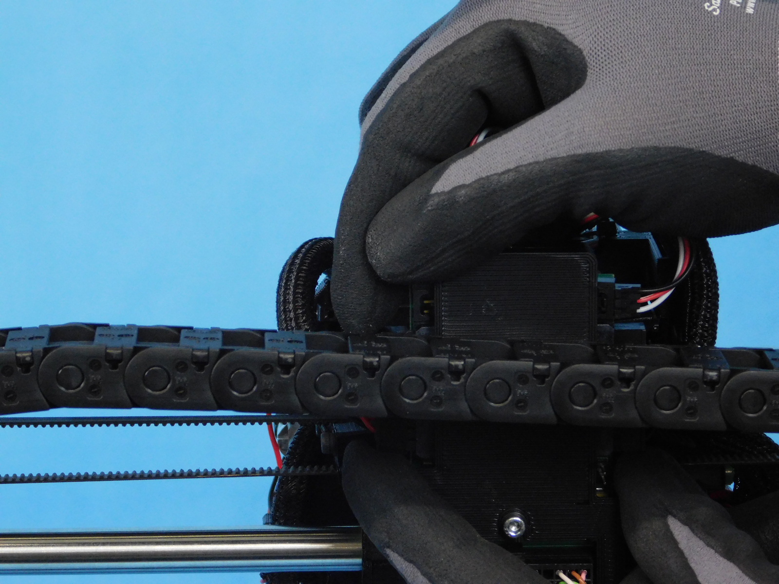
Continue routing the harness around the bottom of the X-Motor End, up the back and to the chain mount on the top of the X-Motor End, attach the cable chain to the cable chain mount.
Attach the other end of the cable chain to the cable chain mount on the X-carriage.
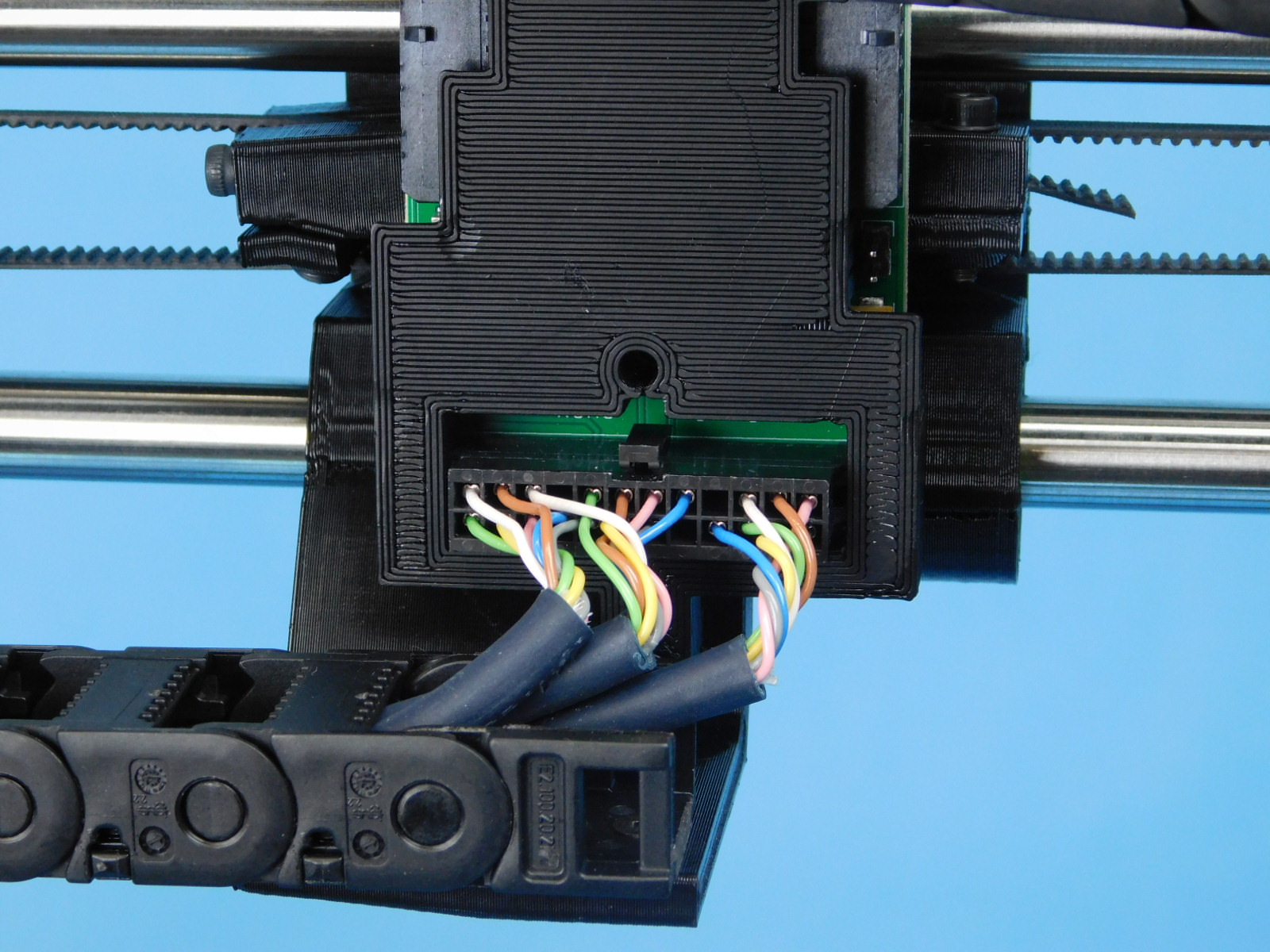
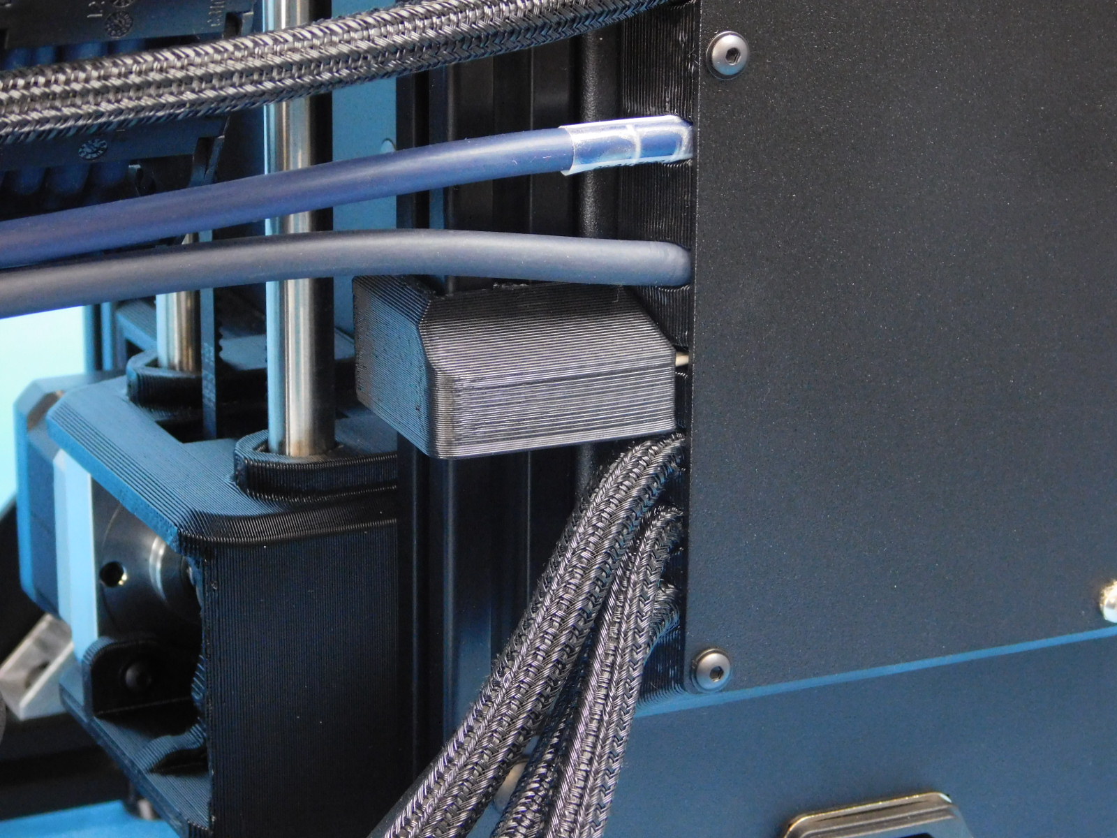
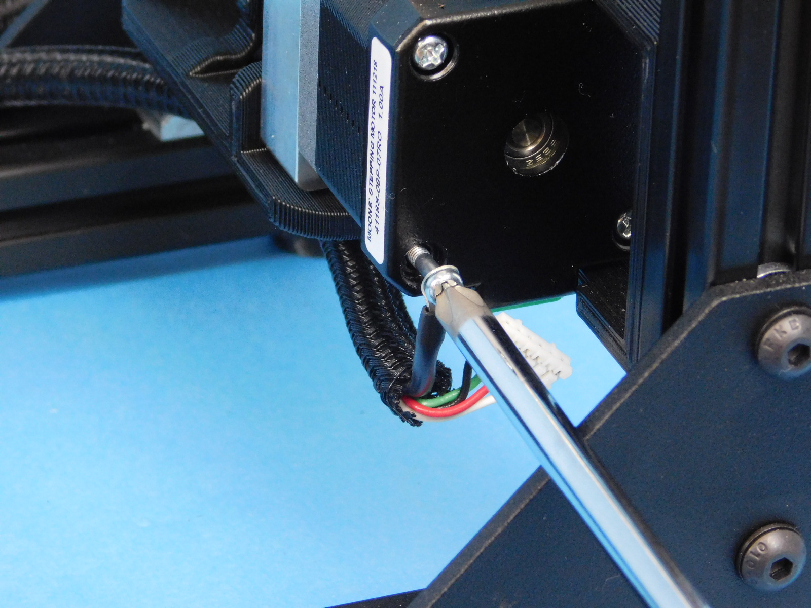
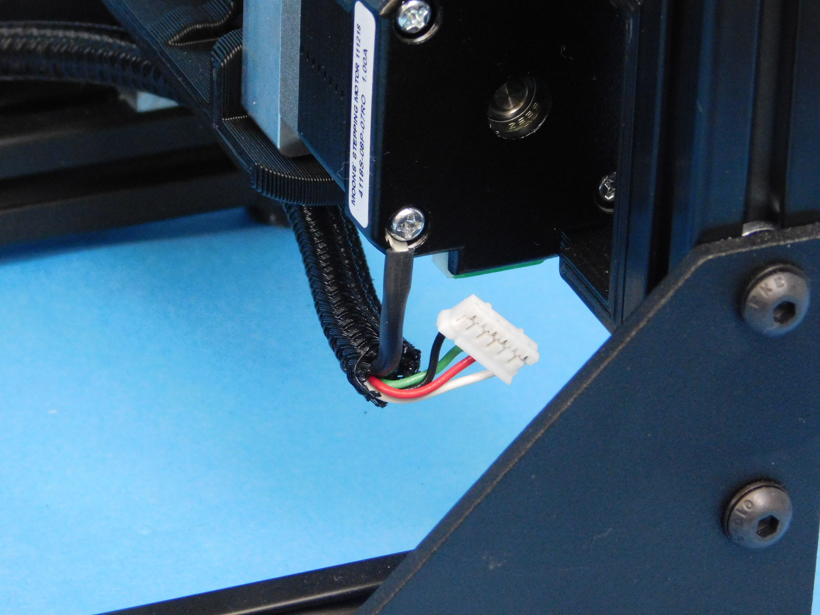
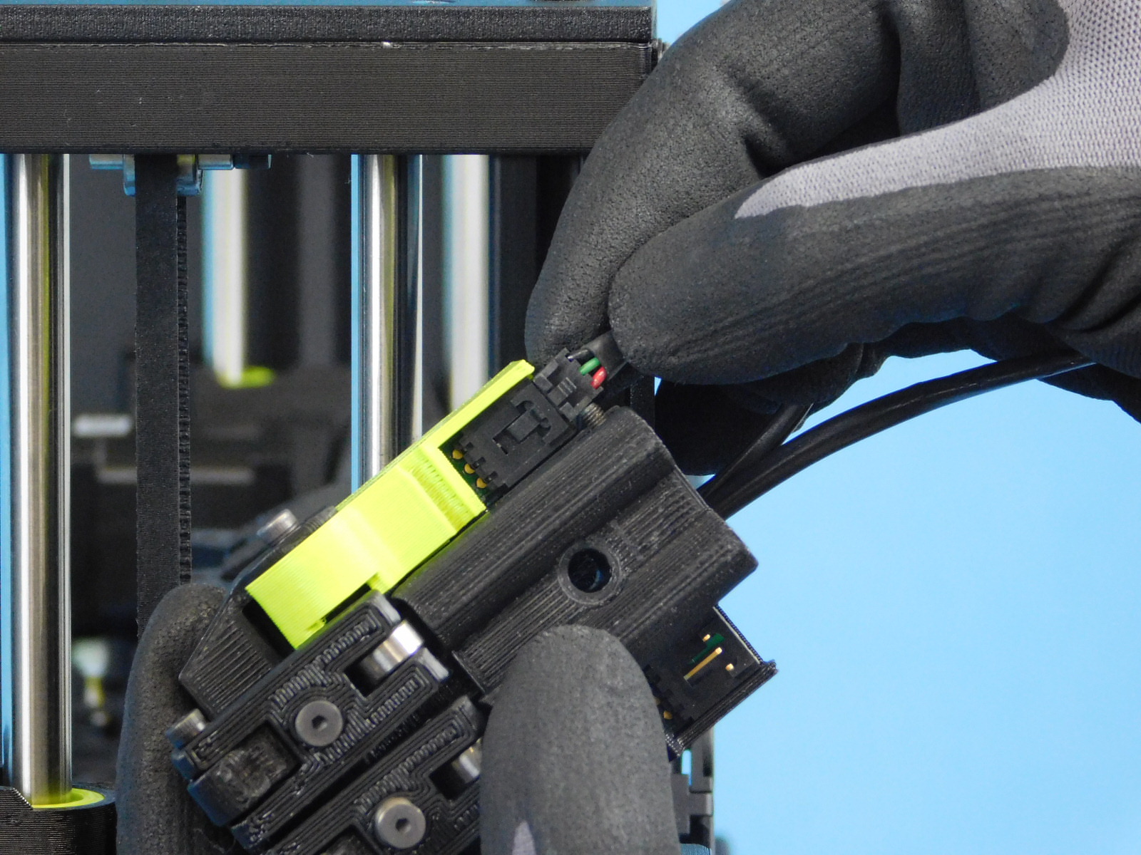
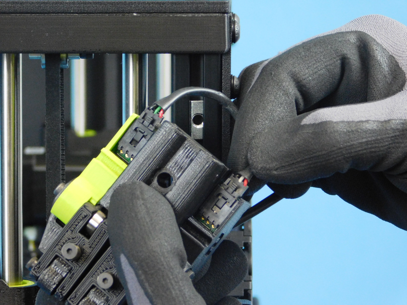
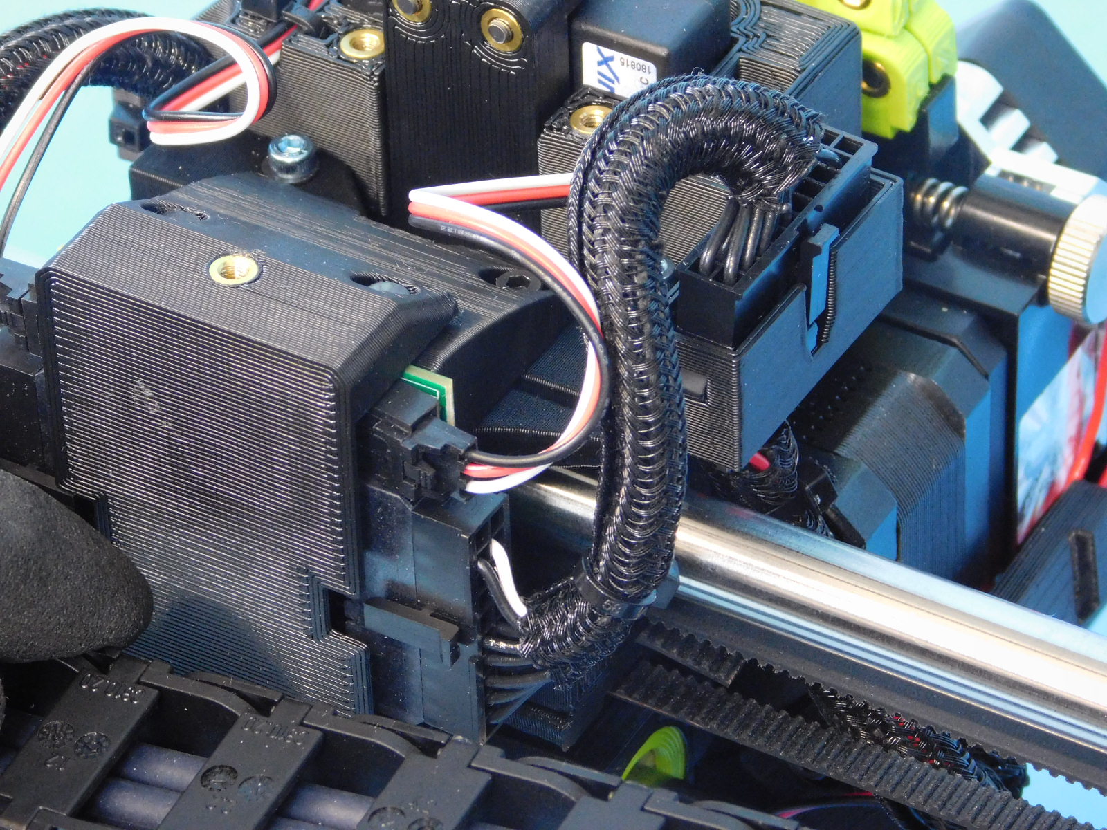
Plug the 22-pin Microfit connector into the Dual Interface Board, do not twist the end.
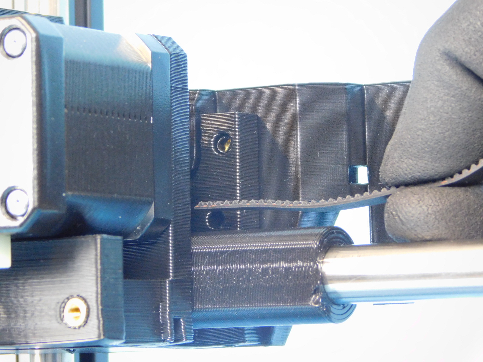
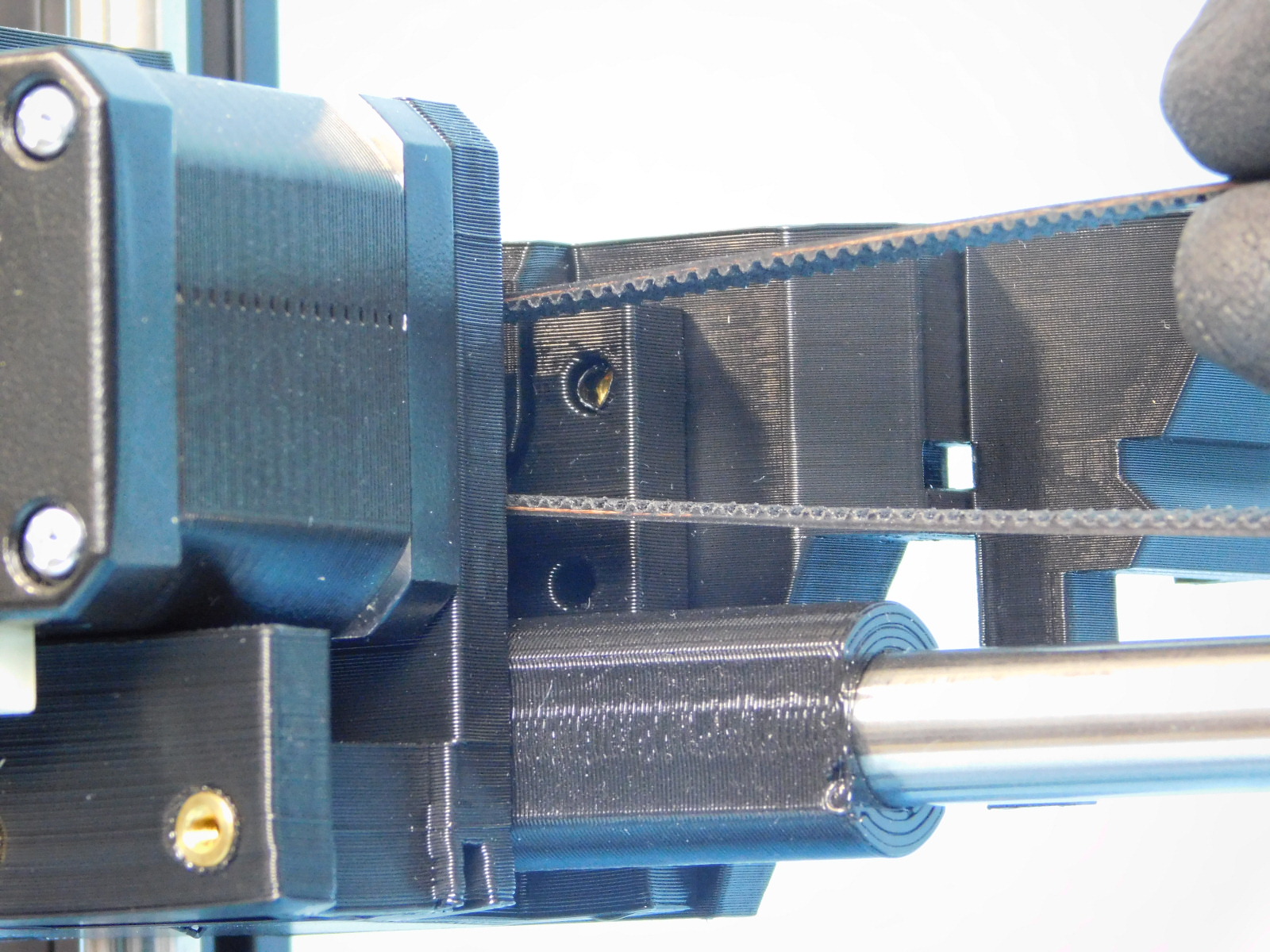
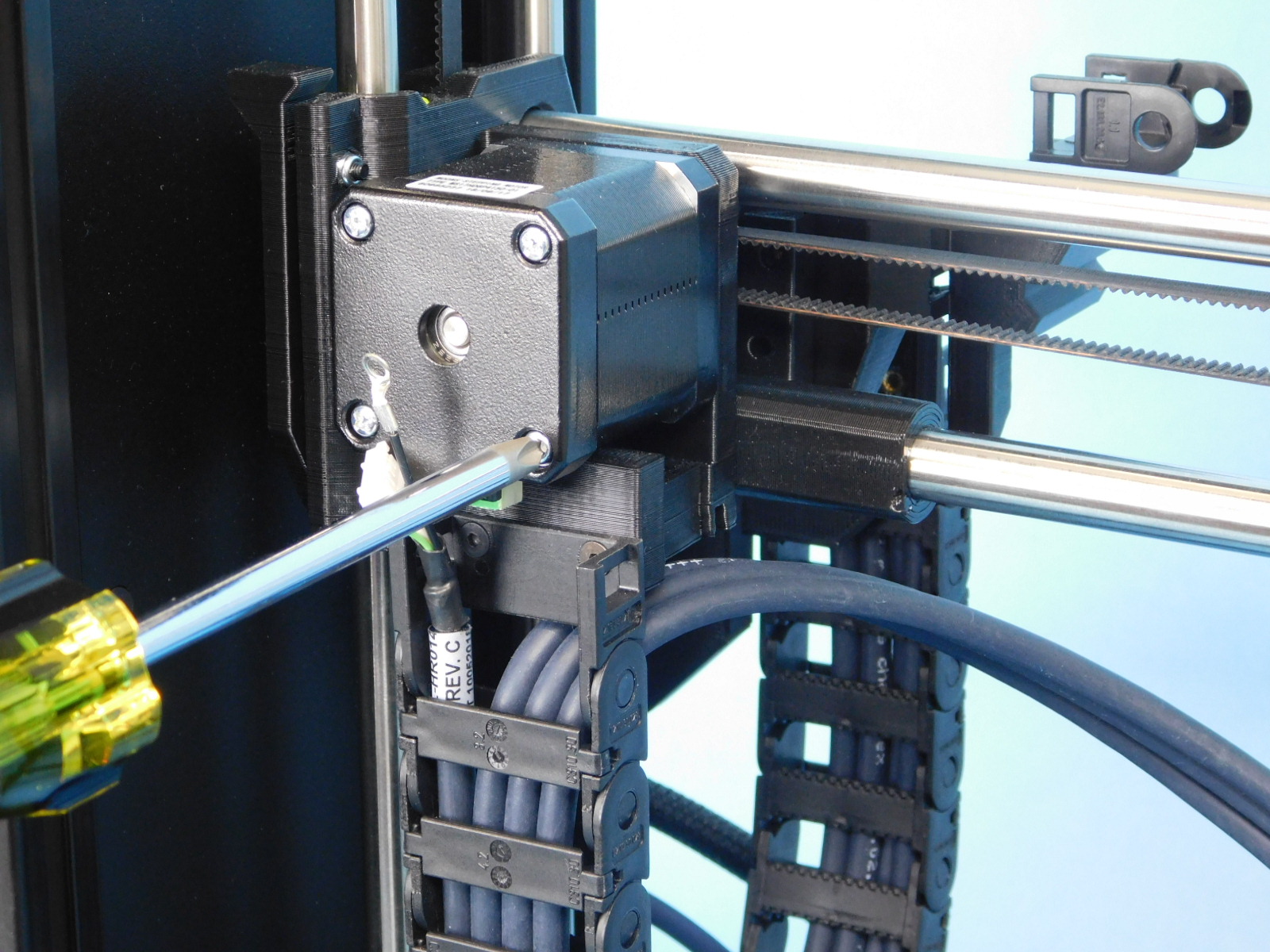
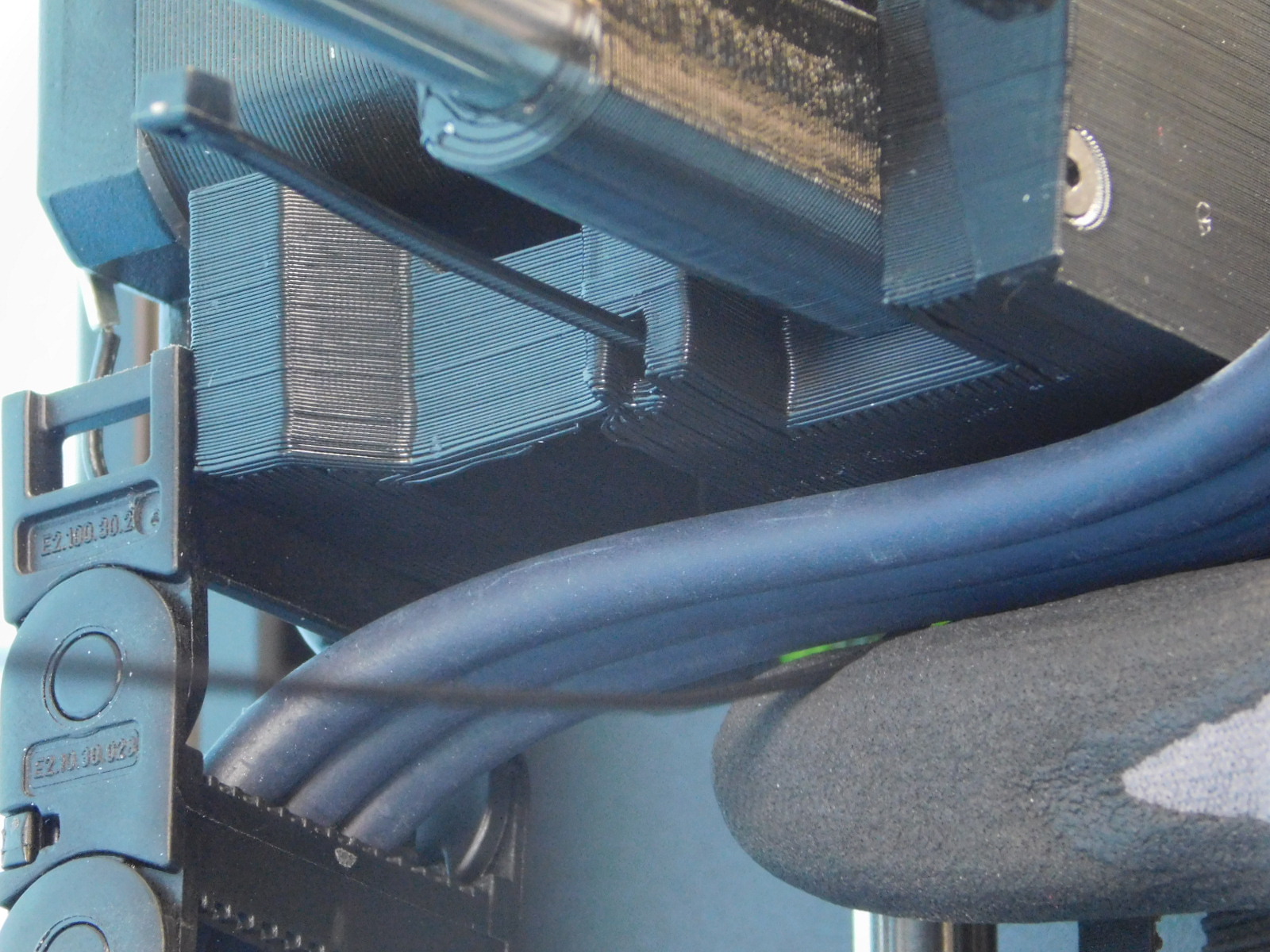
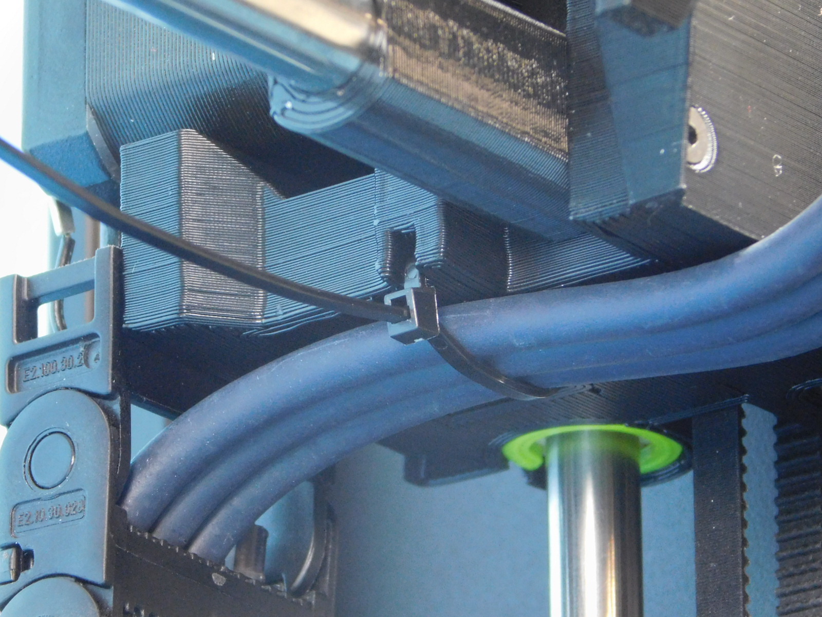
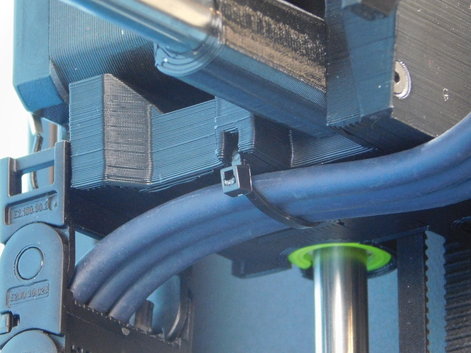
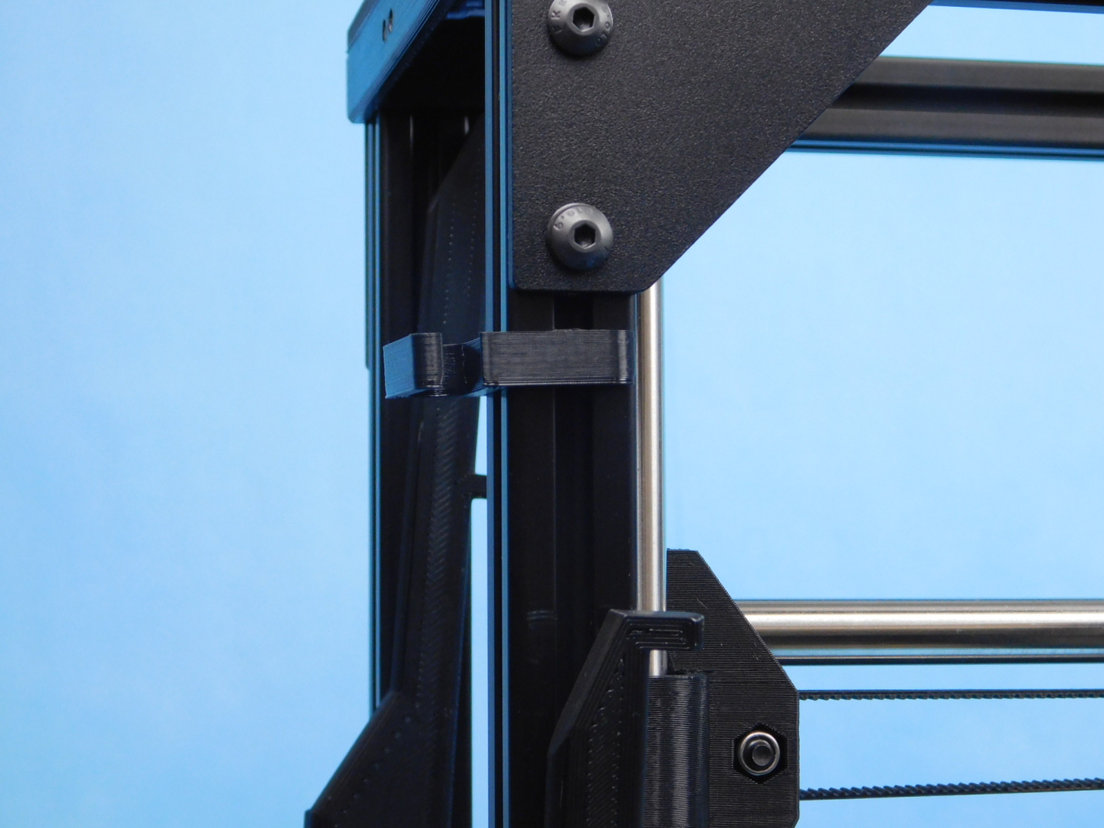
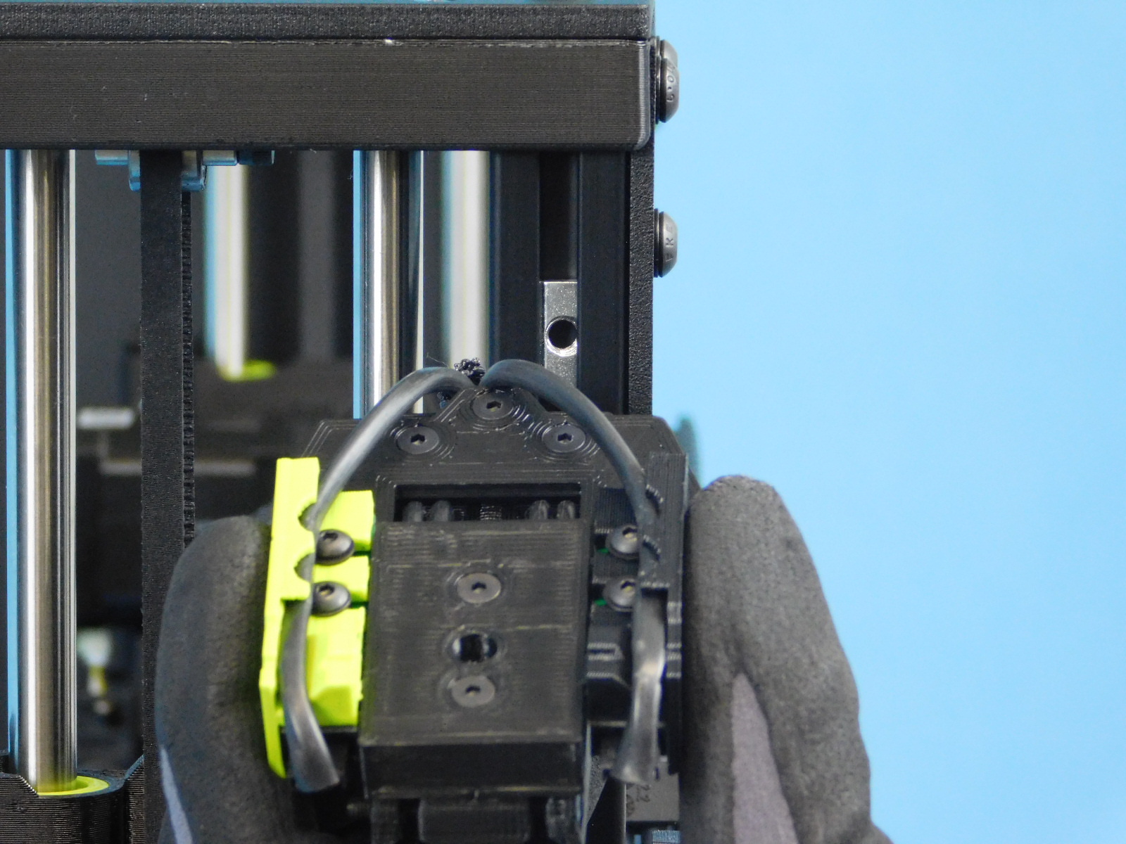
Secure the harness to the X-Motor End using 2x- 8” Black Wire Ties [HD-MS0058] at the locations shown.
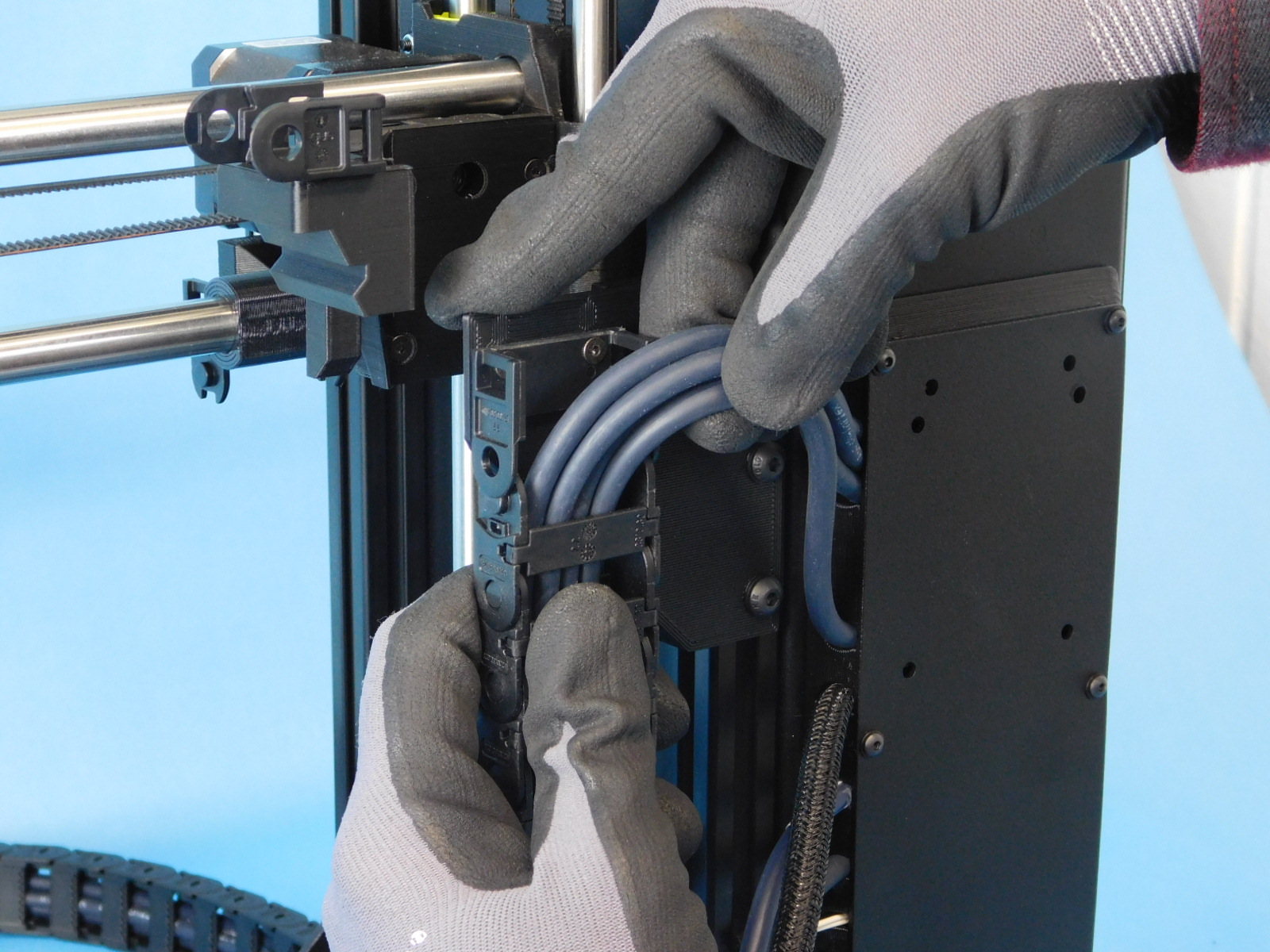


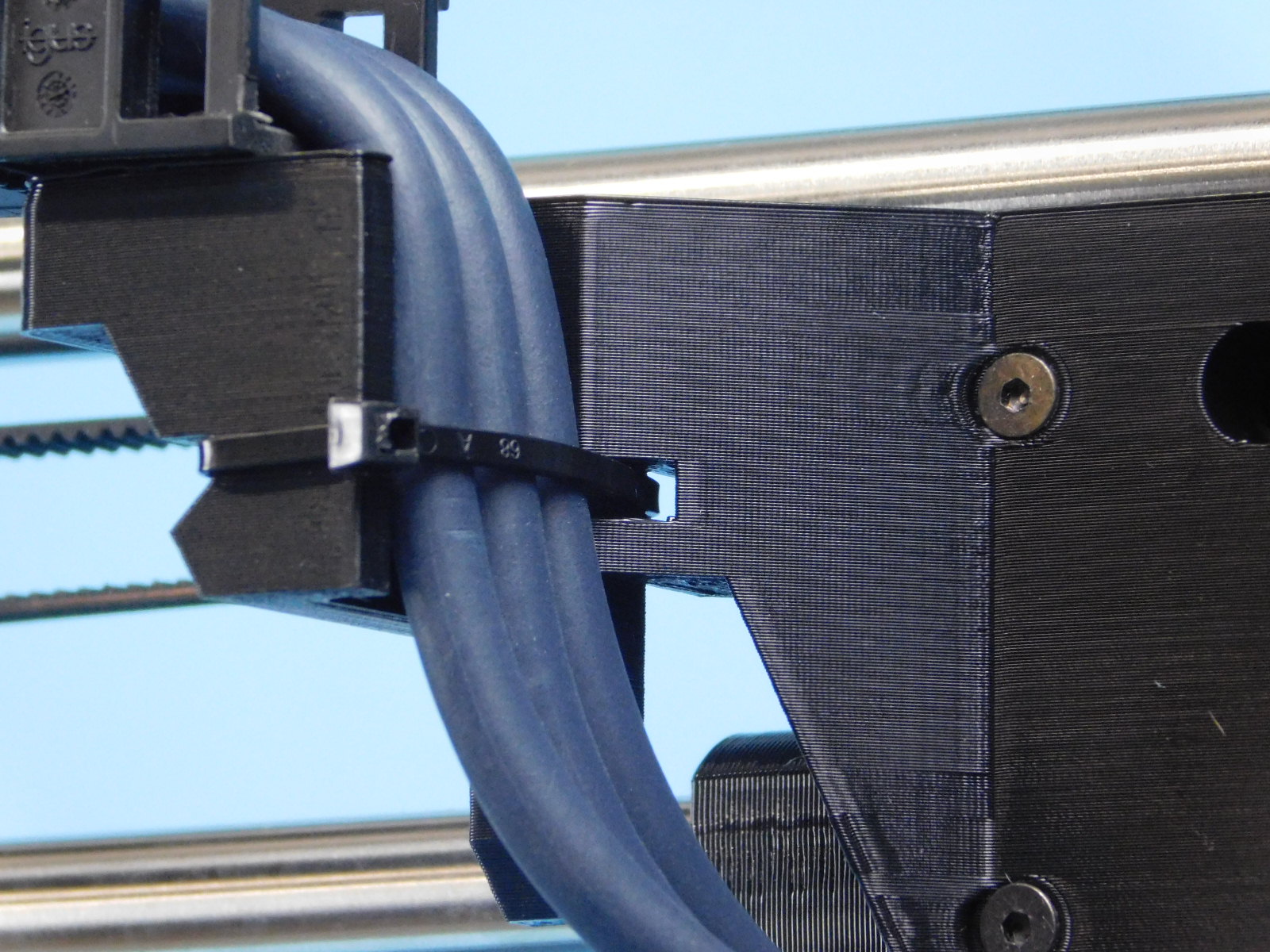
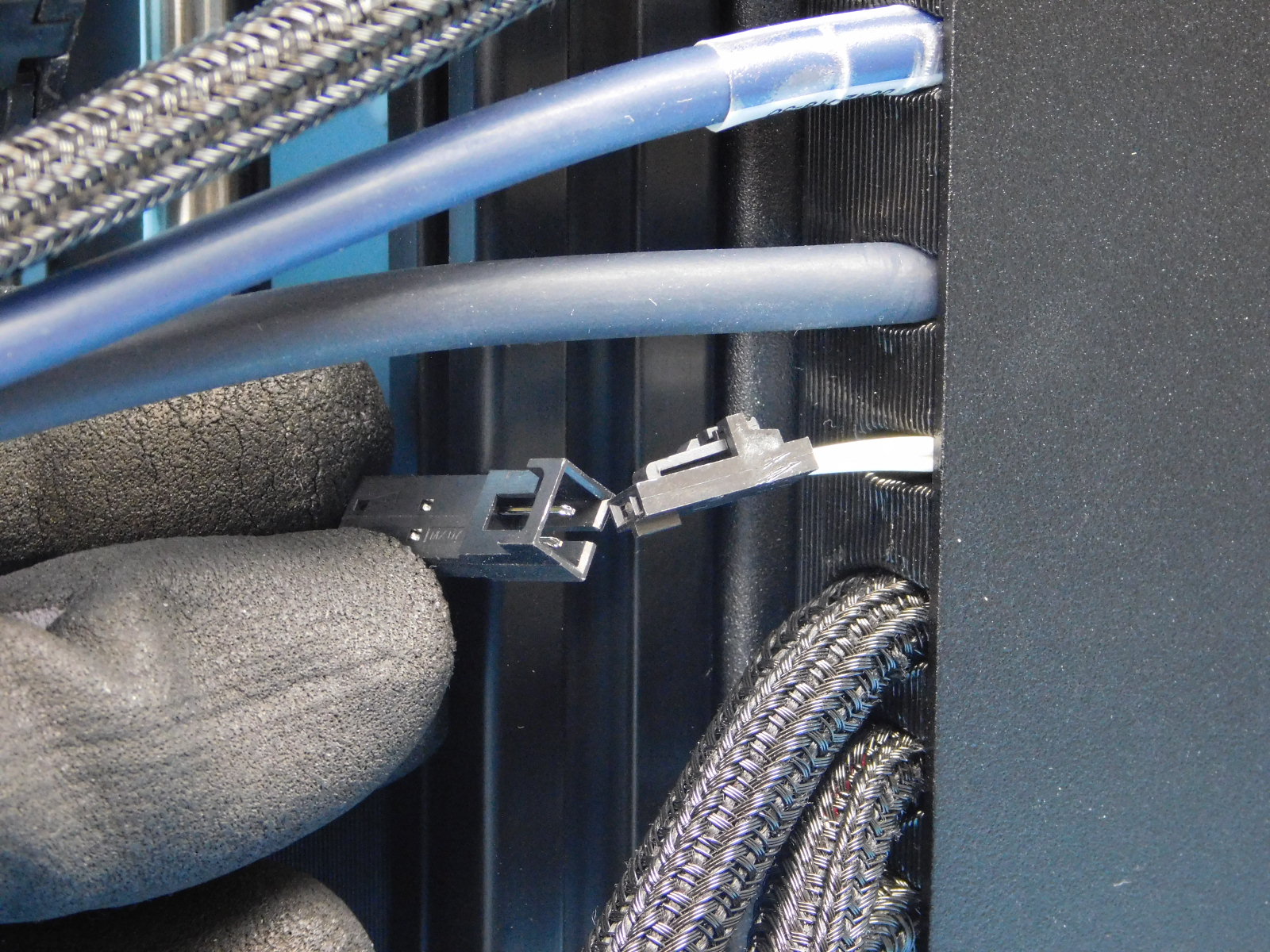
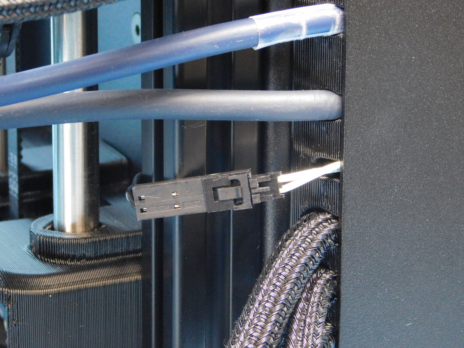
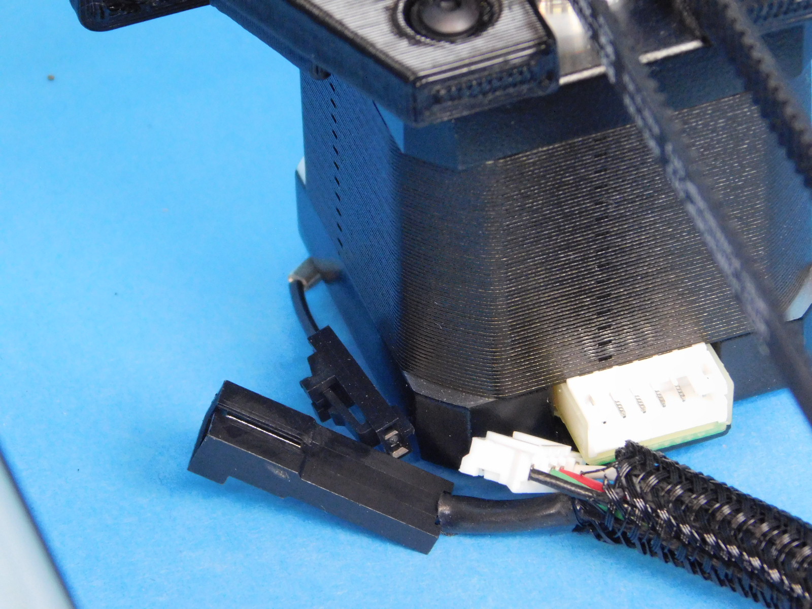
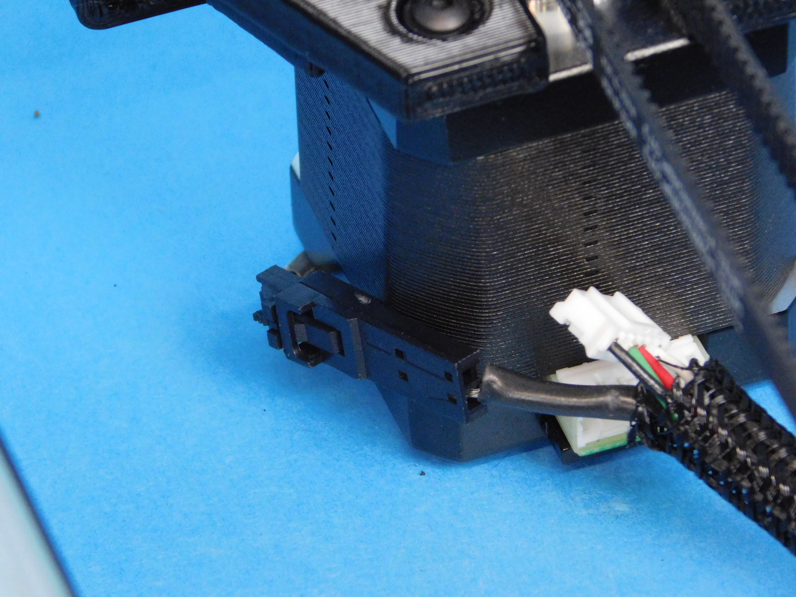
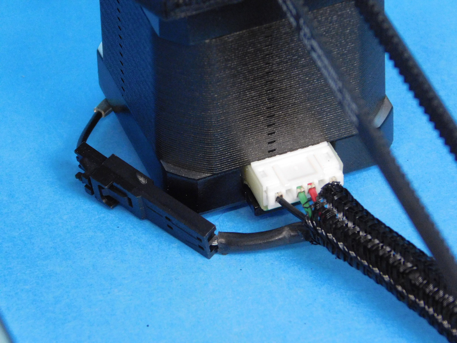
Exiting the Interconnect Housing of the Control Box you will find a 2-pin molex connector, connect it to the other 2-pin molex connector near-by.
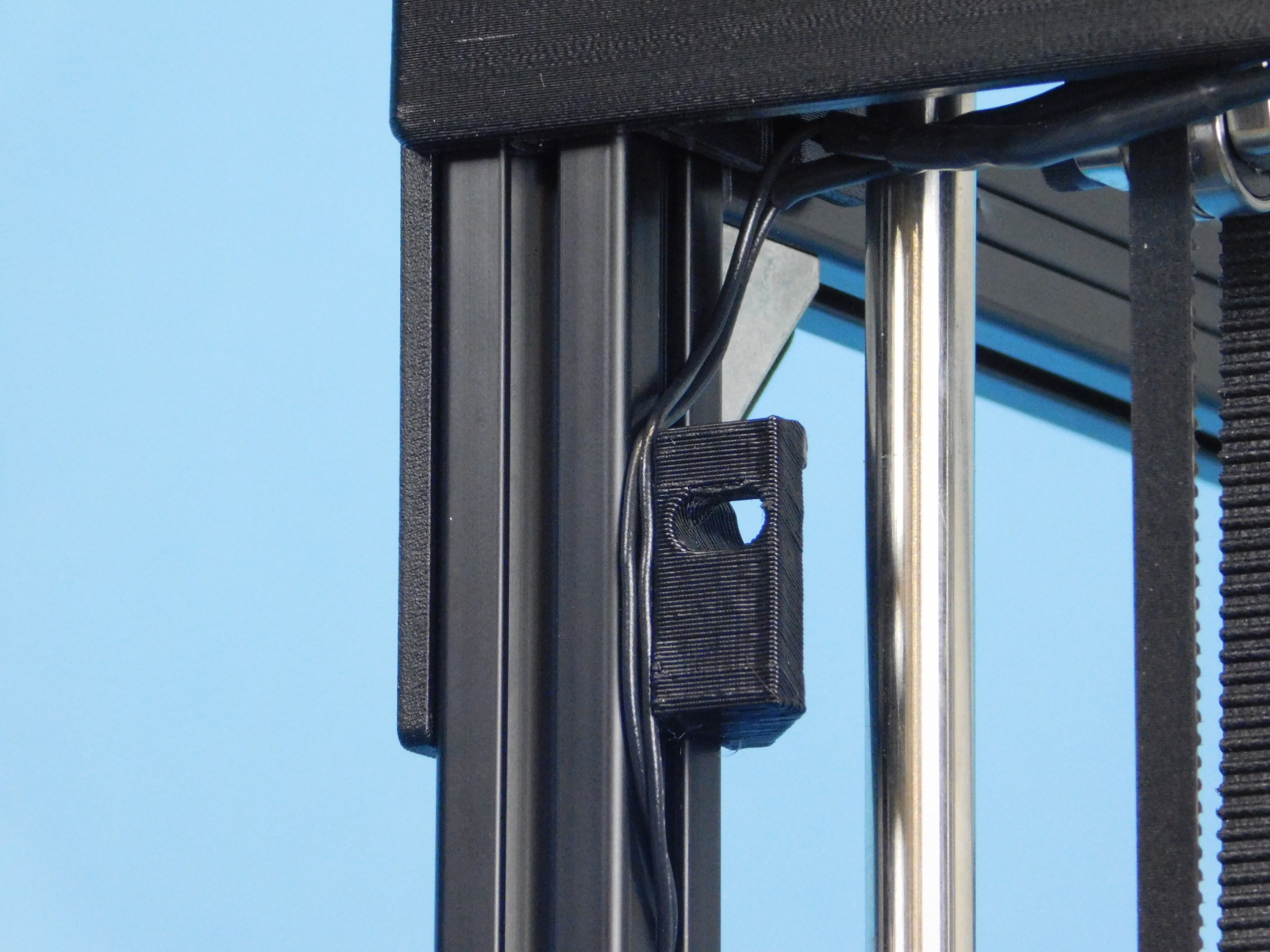
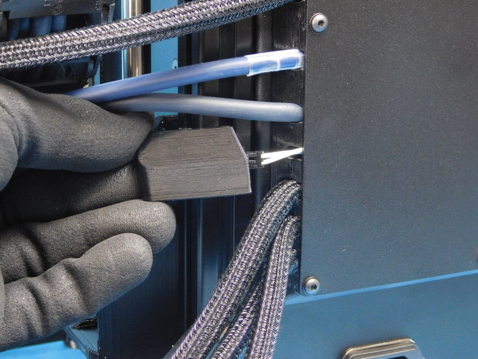
Obtain one Z End stop Cable Cover [PP-GP0405]
Press it into place over the connector as pictured.
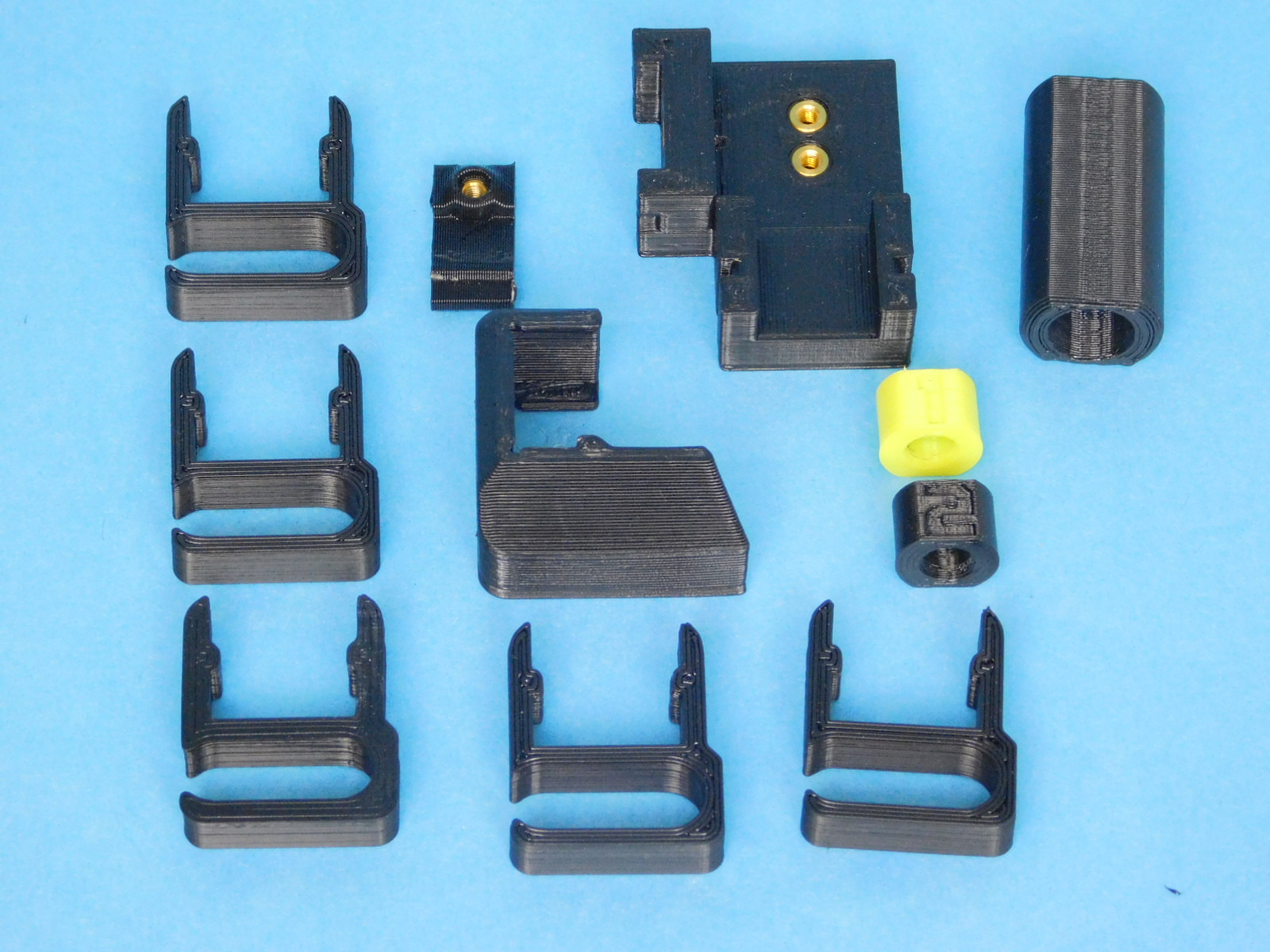
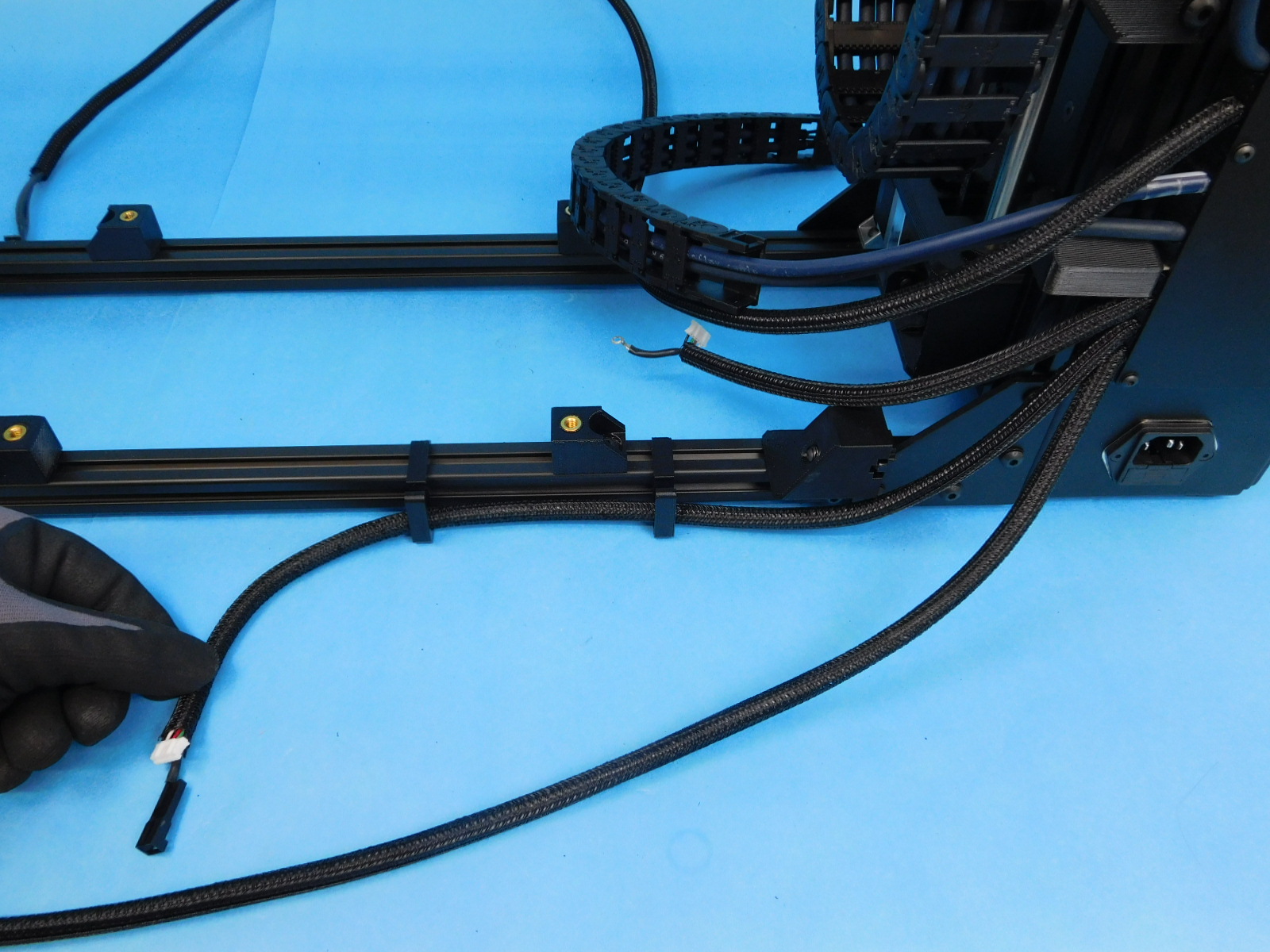
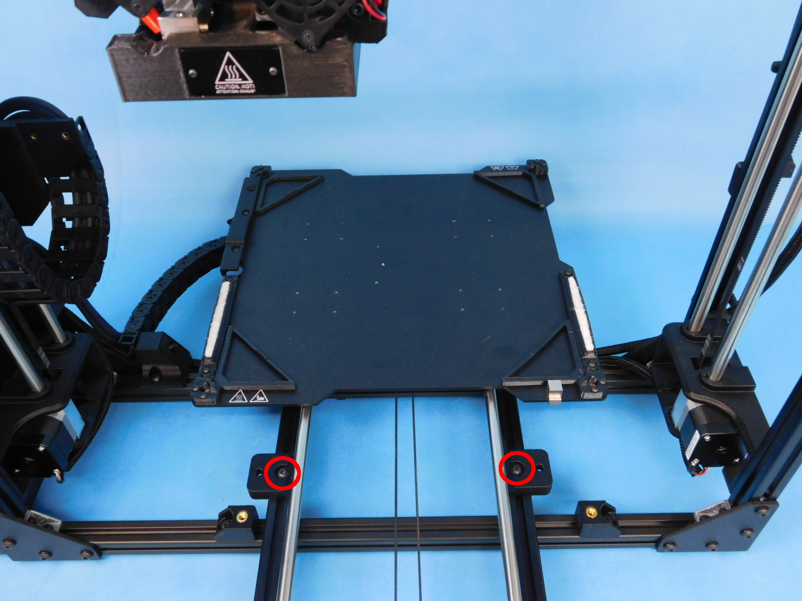
Obtain 5x- Cable Clips [PP-GP0390]
Place one Cable Clip at each location:
Bottom rear frame extrusion:
- between the left Y-Chassis Mount and the Y Cable Chain Mount
- between the left/right Y-Chassis Mount
- between the right Y-Chassis mount and the right rear frame corner
Right rear frame extrusion:
- between z lower right and spool arm
- about 4 inches below the top of the frame
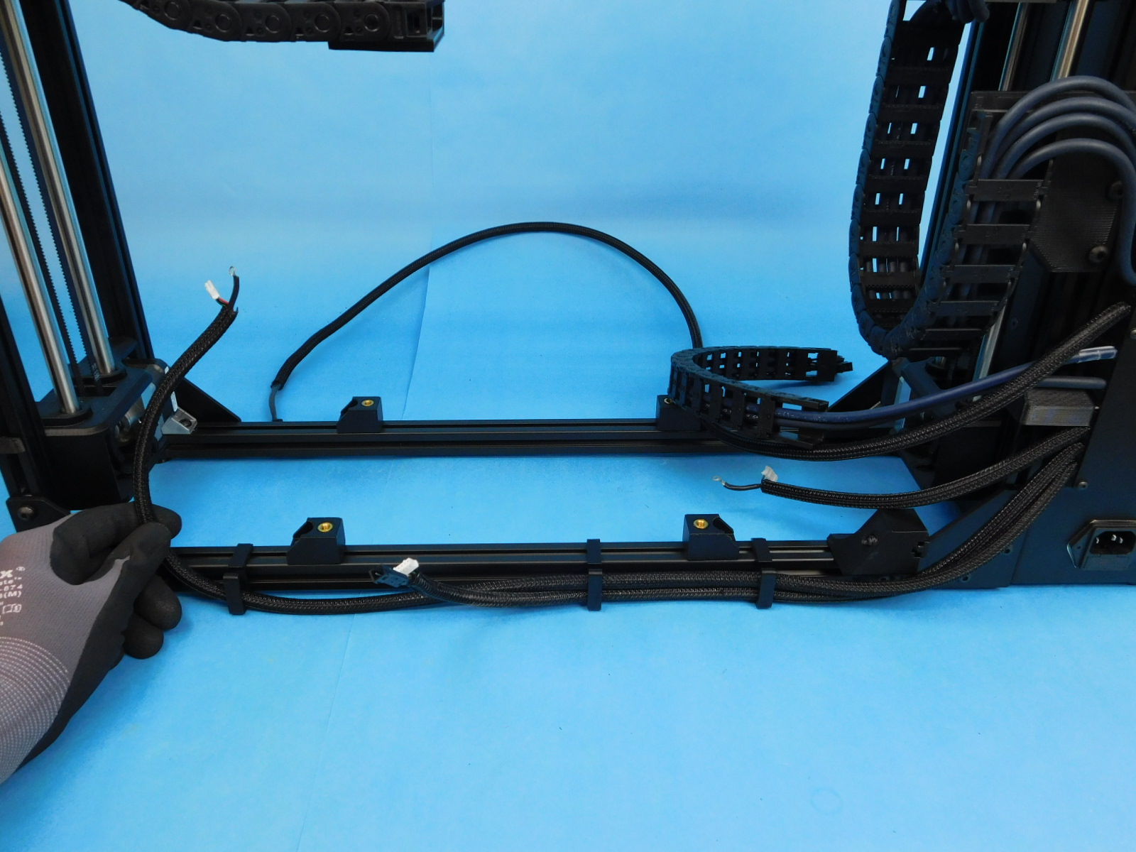
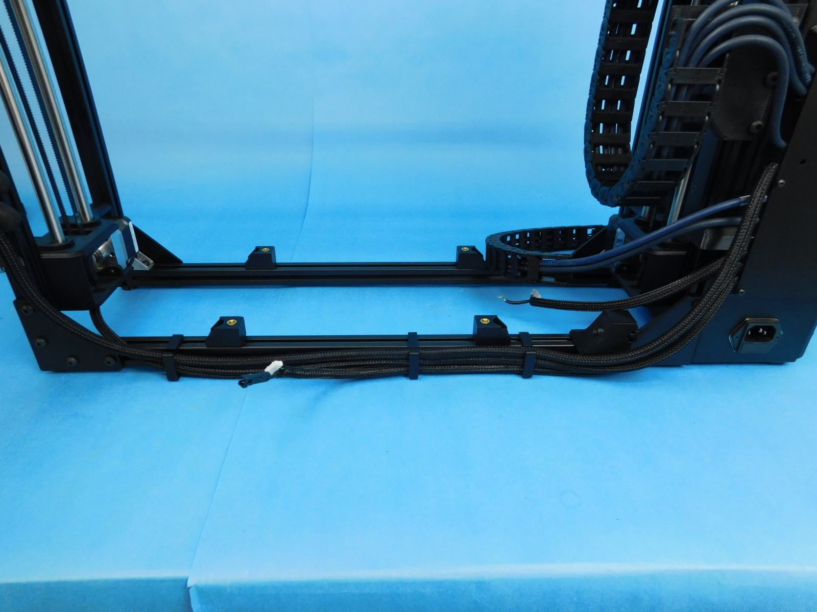
Locate the Y-Motor Harness and route it along the rear of the bottom rear frame extrusion, pushing it into the bottom of both clips.
Locate the Z Right Motor Harness and route it along the rear of the bottom rear frame extrusion, pushing it into the 3 cable clips along the way.
Locate the Filament Sensor Harness and route it along the rear of the bottom rear frame extrusion and up the right side of the right rear frame extrusion, pushing it into all 5 cable clips along the way.


Using a 2mm hex driver, remove the pivot screw from the Y-Cable Chain Pivot Mount.
Be careful, theres a spring on the fastener, don’t lose it.
Attach the pivot to the end of the Y Cable Chain closest to the Control Box using 2x- M3x6 FHCS [HD-BT0128] torque to 5in*lbs
Re-attach the pivot to the Y Cable Chain Pivot Mount by reinstalling the pivot screw.
Obtain 1x- Y Chain to Bed Mount w/ Inserts [PP-IS0103]
Attach it to the other end of the Y Cable Chain in the orientation shown using 2x- M3x6 FHCS [HD-BT0128] torqued to 5in*lbs
Pick up and rotate the assembly so the front is facing you.
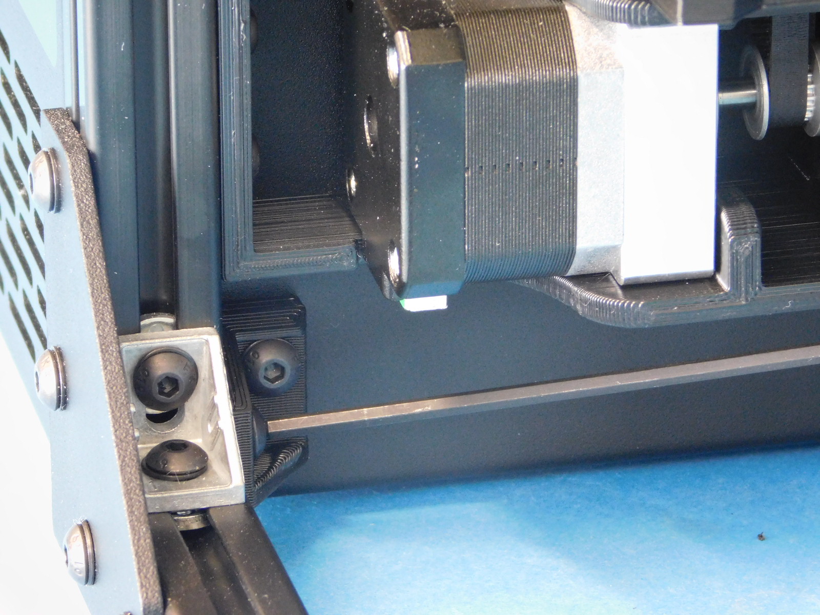
Using a P2 Phillips driver, remove the highlighted fastener from the Z-Left Motor.
Slide the terminal ring from the Z-Left Motor Harness onto the fastener and re-insert it into the hole it was removed from, tightening firmly.
Connect the JST connector from the Z-Left Motor Harness to the Z-Left Motor.
Again using a P2 Phillips driver, remove the highlighted fastener from the Z-Right Motor.
Slide the terminal ring from the Z-Right Motor Harness onto the fastener and re-insert it into the hole it was removed from, tightening firmly.
Connect the JST connector from the Z-Right Motor Harness to the Z-Right Motor.


Obtain one Filament Sensor Assembly [AS-PR0144]
Connect the Filament Sensor Harness to the Filament Sensor Assembly; the 3-pin connector with the green wire goes to the green side of the filament sensor assembly, the other to the black side.
Place the harnesses into the grooves as pictured.
Obtain 2x- Sensor Cable Cover [PP-GP0426]
Install one Sensor Cable Cover over each connector as pictured.
Attach the Filament Sensor Assembly [AS-PR0144] to the frame using one M5x25 SHCS [HD-BT0196]
Side the Filament Sensor Assembly up as far as it goes.
Torque to 5in*lbs
Ensure the harness has not become pinched between the sensor assembly and the frame


Obtain:
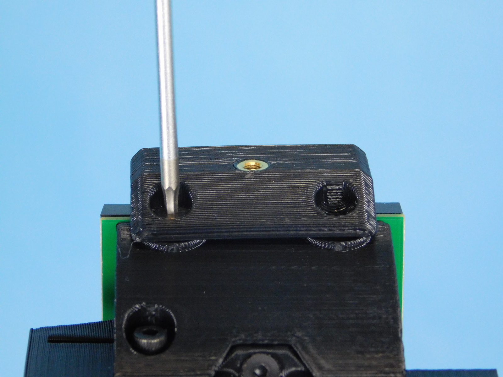
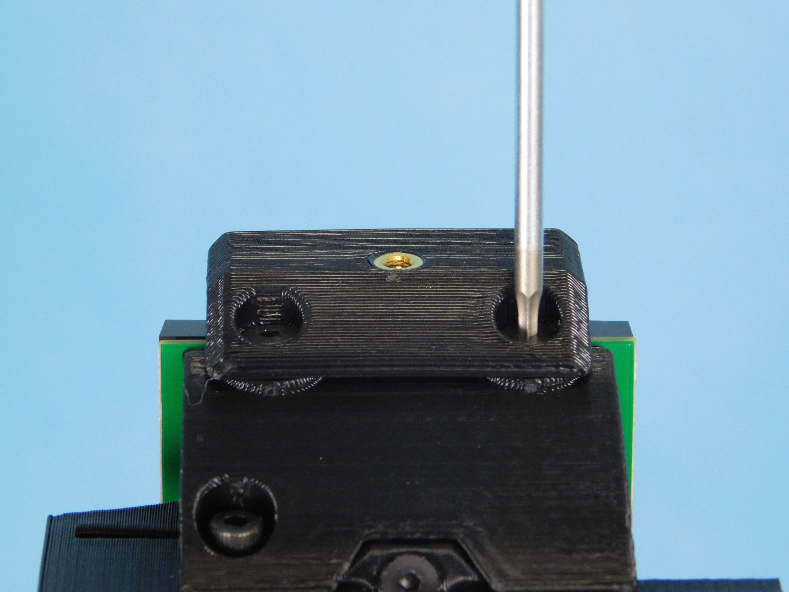
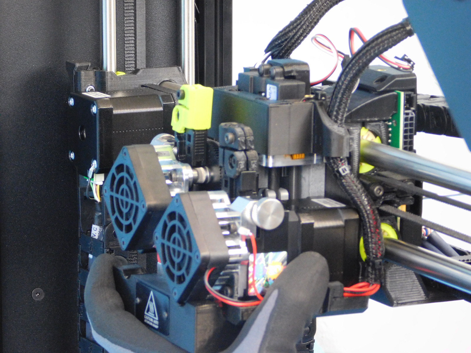
1x- ServoDual Toolhead [AS-TH0074]
1x- Stainless Steel SHCS M3x55 [HD-BT0248]
2x- Stainless Steel SHCS M3x16 [HD-BT0249]
3x- M3 Washers, Black-Oxide [HD-WA0038]
Place the M3x55 Steel SHCS [HD-BT0248] through the hole in the Interface Board Cover (rear of the carriage).
Line up the ServoDual Toolhead with the carriage and thread the screw inserted from the rear into the mount.
Install 2x- M3x16 Steel SHCS [HD-BT0249] with washers [HD-WA0038] to secure the tool head from above.
Torque all 3 fasteners to 5in*lbs
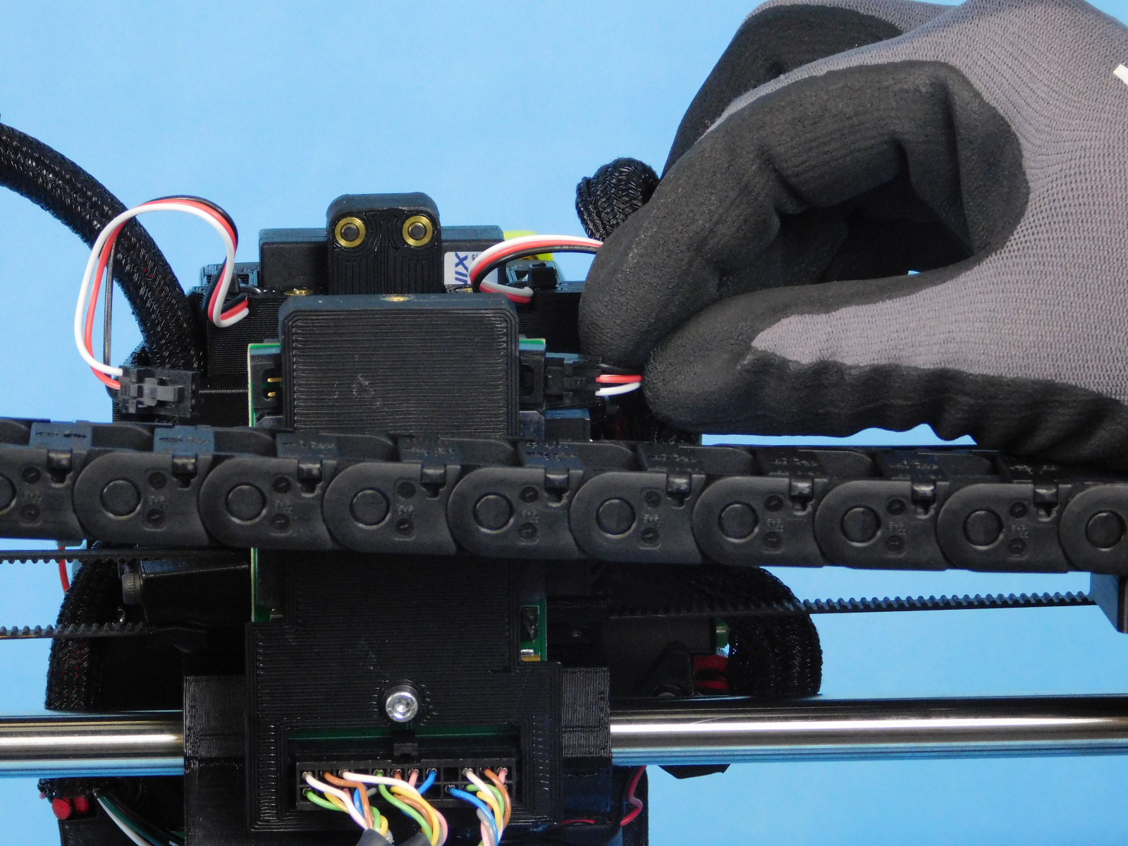
Connect the E1 Harness and E1 Actuator to the left side of the Dual Interface Board, as pictured.
Connect the E2 Harness and E2 Actuator to the right side of the Dual Interface Board, as pictured.


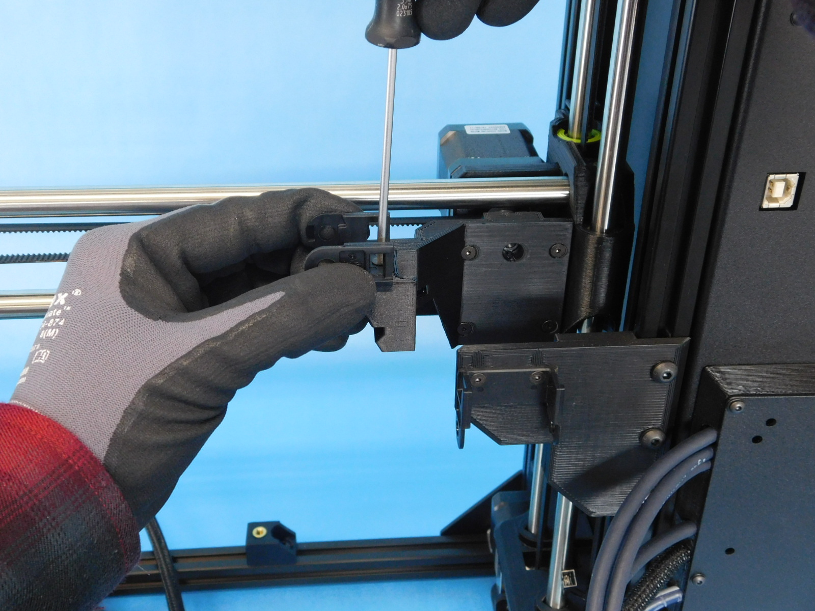
Obtain one completed Y-Axis Assembly [AS-PR0125]
Loosen the right 2 Y-Chassis mounts on the bottom rails of the printer frame and slide them to the right.
Place the Y-Axis on top of the bottom frame rails with the motor end of the axis away from you.
Loosen the fasteners securing the Y Table Mounts to the Y-Axis frame.
Slide the left Y-Table mounts into place over the Y-Chassis Mounts.
Slide the right Y-Chassis mounts back to the left against the right side of the right Y-Axis frame extrusion, position the right side Y-Table Mounts on top of them.
All 4 Table mounts should now be on top of all 4 Chassis Mounts, and the Y-Axis frame extrusions resting on the bottom frame extrusions.
Install one M5x14 Thumb Screw [HD-BT0231] through each table mount, into the insert in the Chassis mounts.
Tighten securely by hand.


Place the Y-Axis rear spacer (printed jig) on the top rear of the left Y-Axis frame extrusion between the Y-Corner and the Y-Table Mount, as pictured.
Slide the Y-Axis frame forward so that the spacer jig cannot be wiggled back and forth.
Tighten the fastener securing the left table mounts to the y-axis frame.
Torque to 5in*lbs
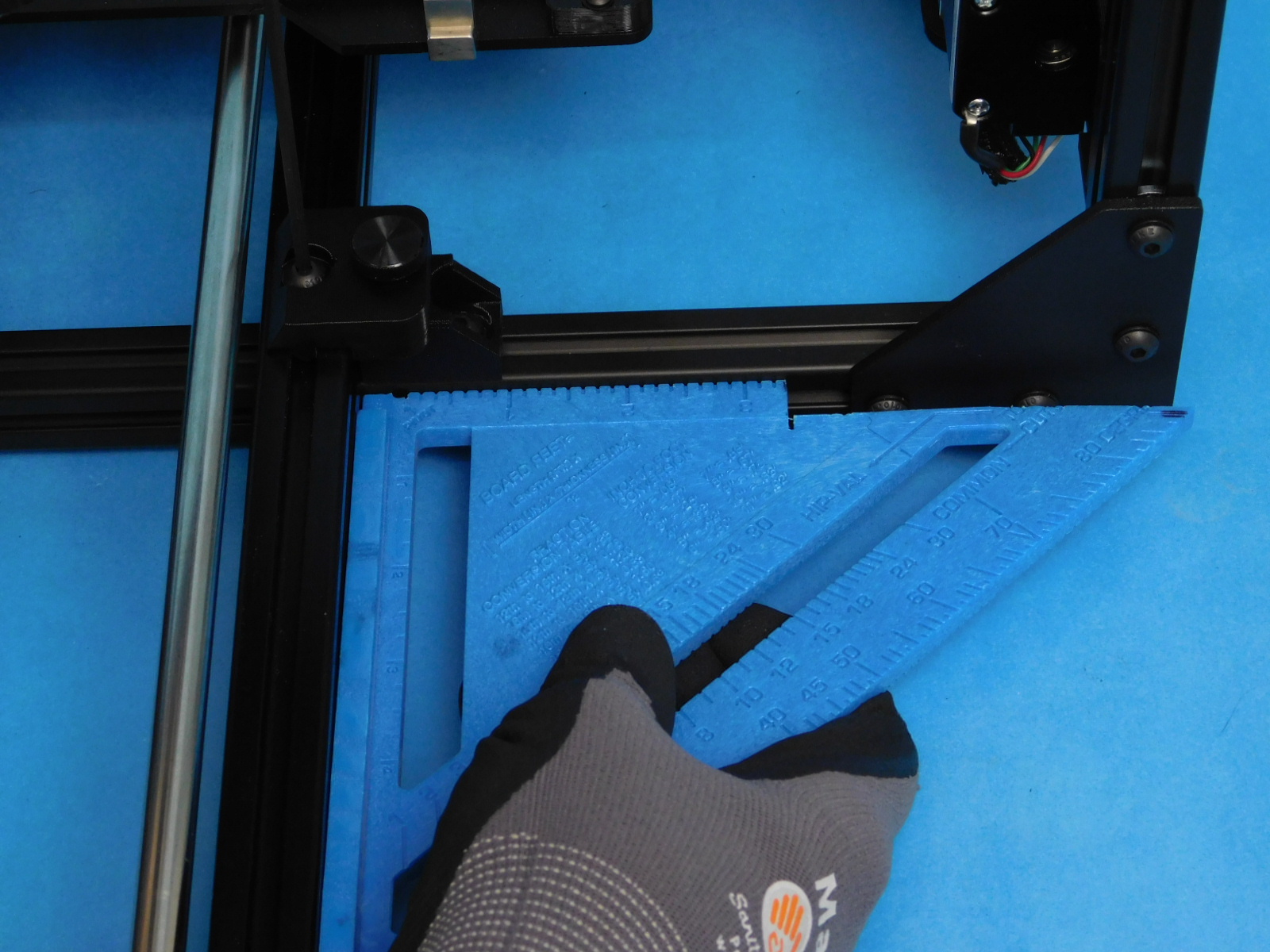
Place the pre-cut Y-Frame square at the location shown.
Move the right Y-Axis frame forward or back slightly until it is square; you should not be able to wiggle the square and there should be no gaps.
Tighten the right chassis mount and table mount fasteners.
Torque to 5in*lbs
Double check with the square to ensure proper alignment.
Connect the 2-pin connector at the Y-Motor to the 2-pin connector on the Y-Motor Harness.
Connect the JST of the Y-Motor Harness to the Y-Motor.
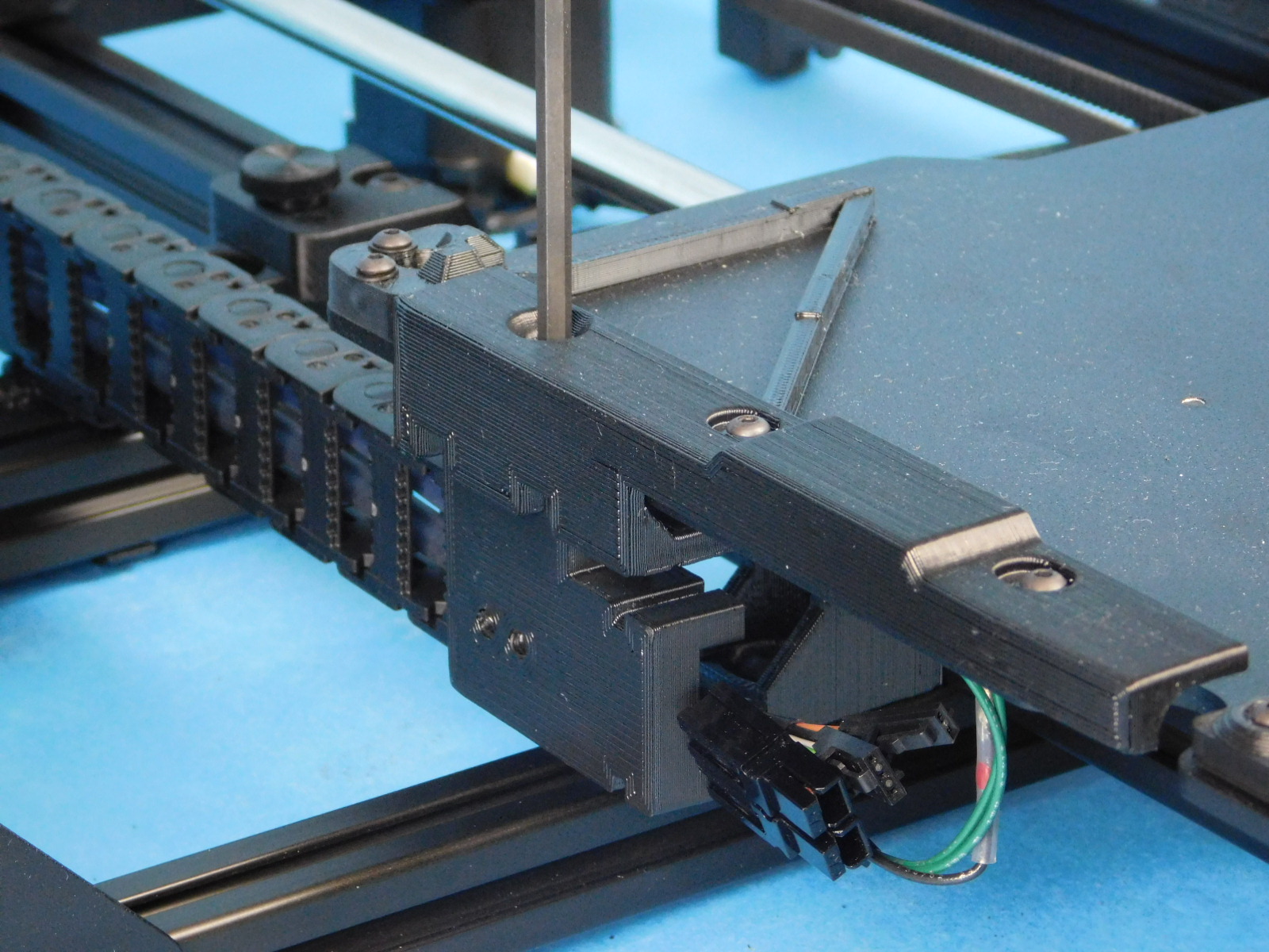
Obtain one Y Chain to Bed Mount with Inserts [PP-IS0103] and 2x- M3x6 FHCS [HD-BT0128]
Attach the Y Chain to Bed Mount to the end of the Y Cable Chain in the orientation shown using 2x- M3x6 FHCS [HD-BT0128]
Torque to 5in*lbs
Using a ball-tipped 4mm hex driver, attach the Y Chain to Bed Mount to the bed plate.
Tighten securely.
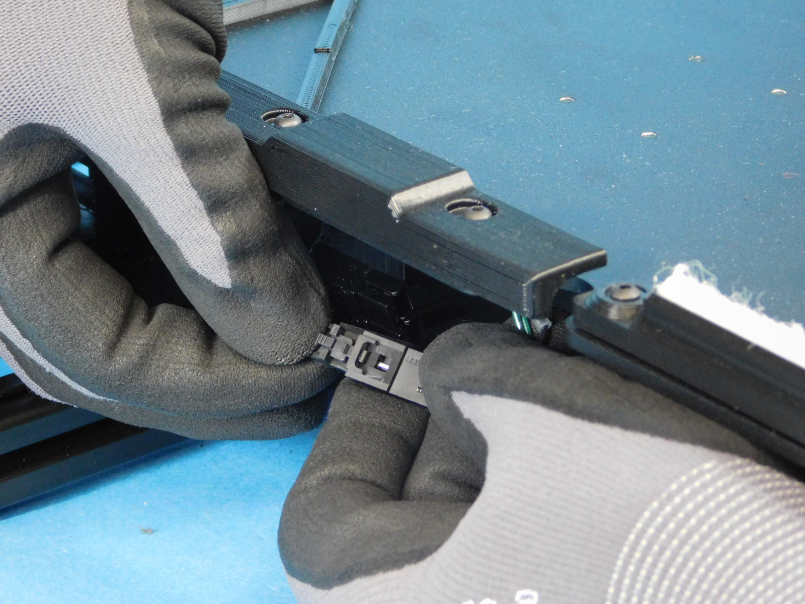
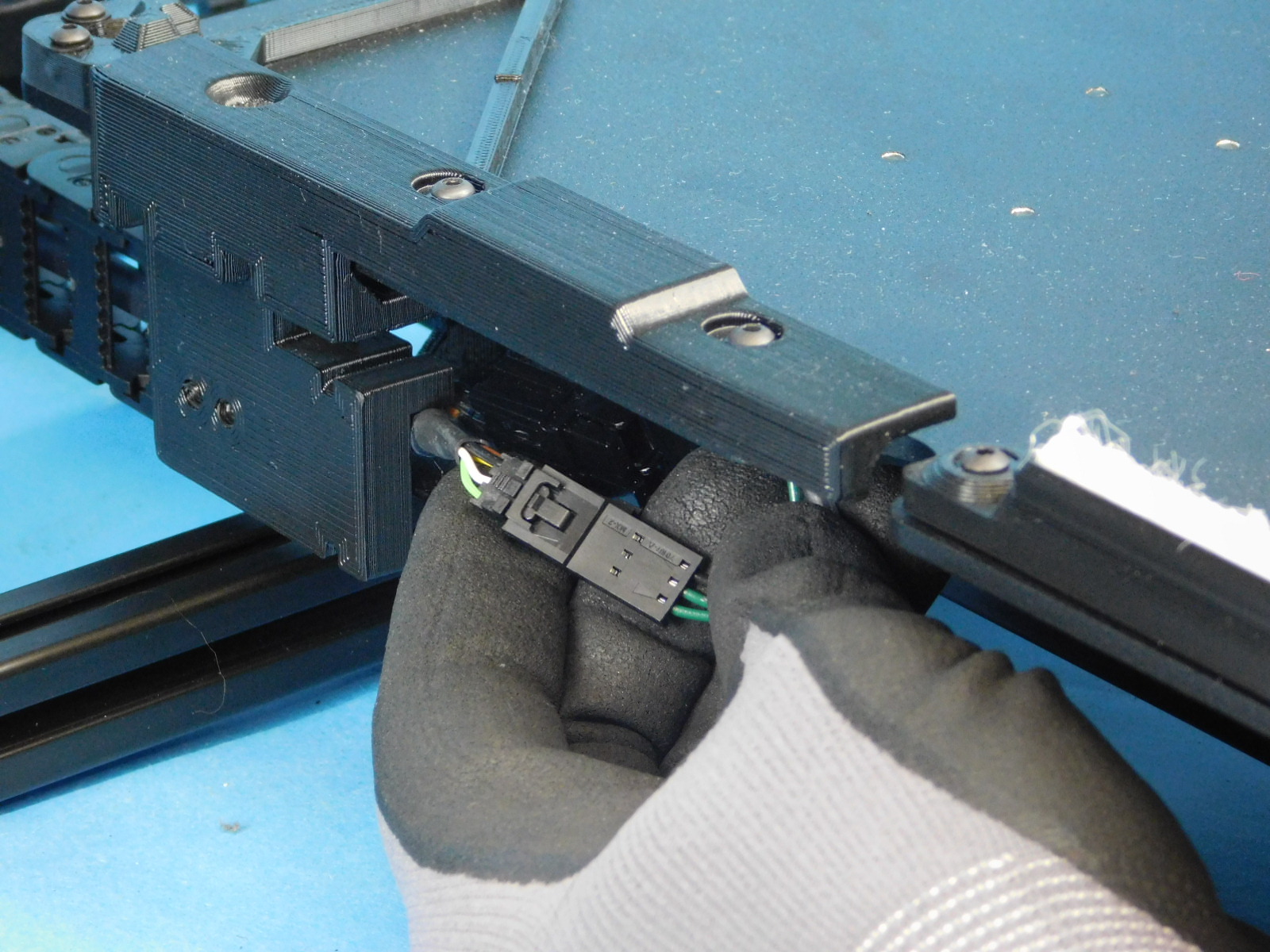
Connect the two 3-pin connectors underneath the bed plate.
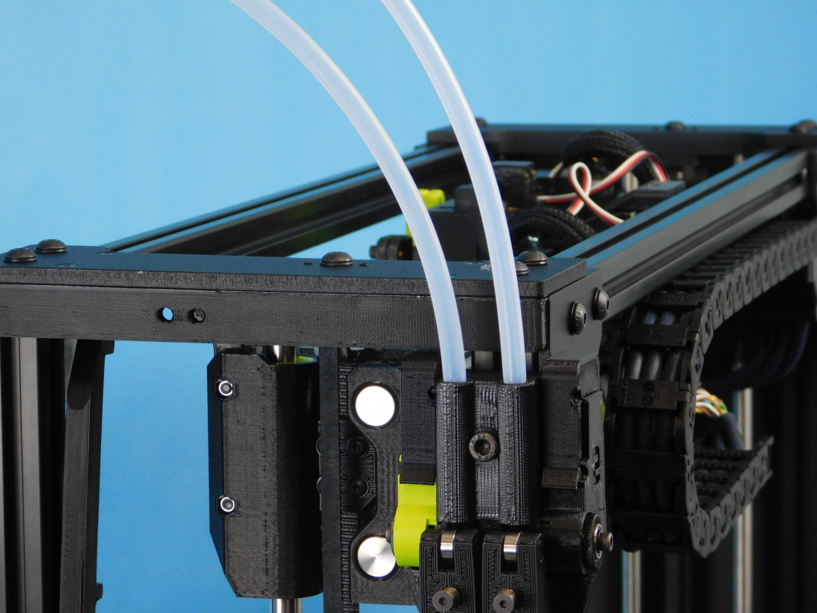
Obtain:
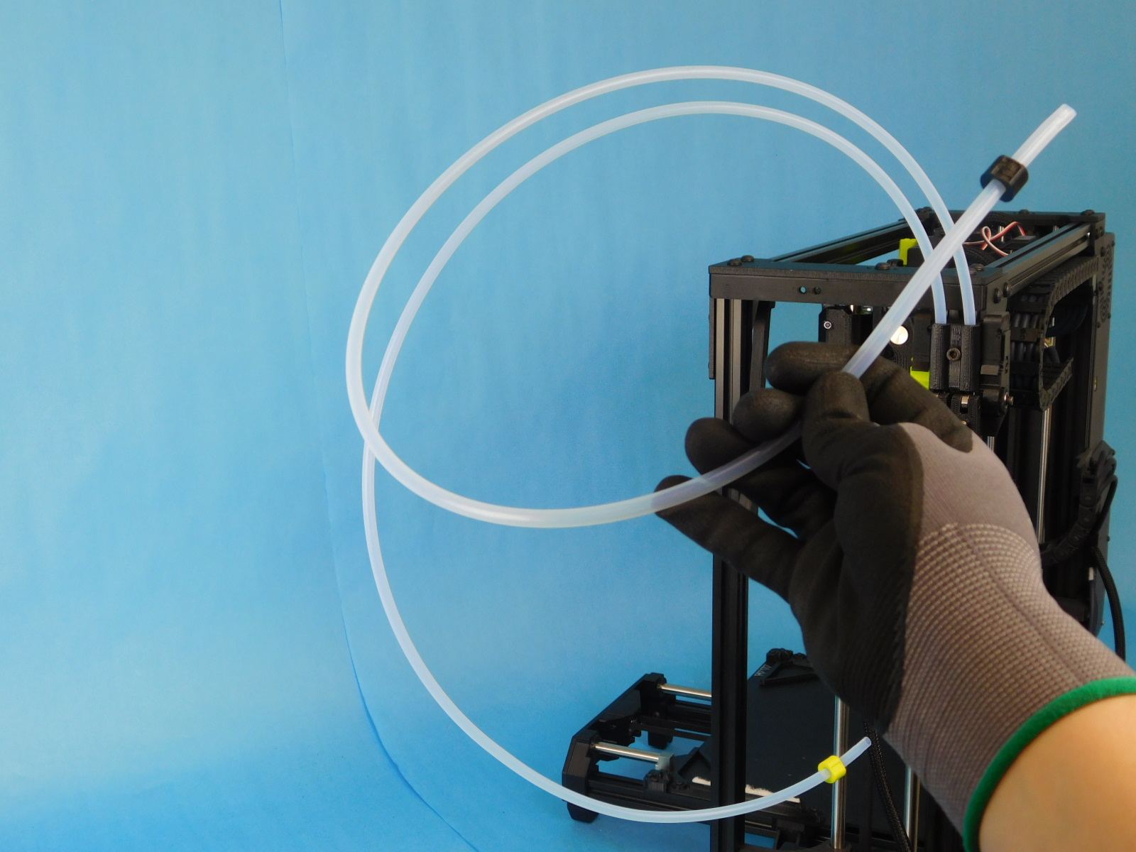
2x- PTFE Feed Tube (Cut) [AS-PR0149]
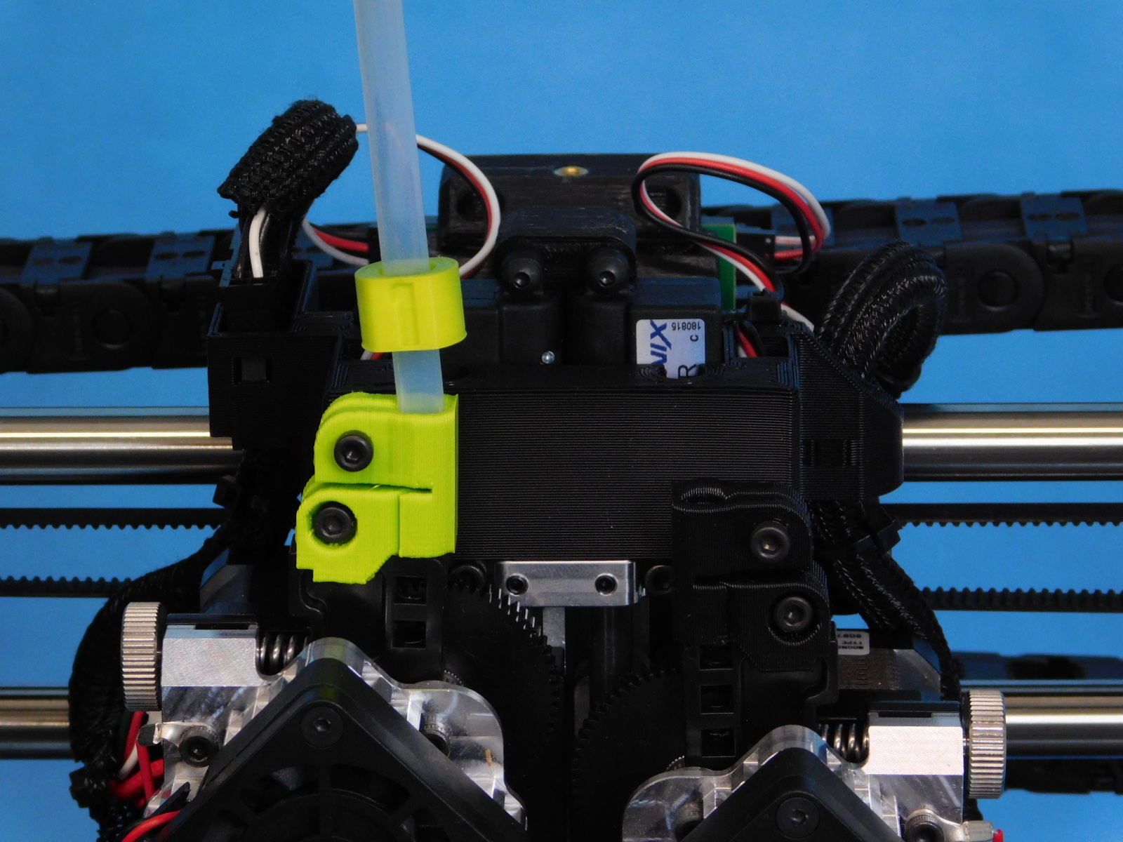
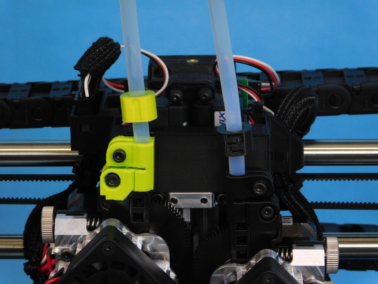
1x- Tube Collar 1 [PP-GP0430]
1x- Tube Collar 2 [PP-GP0431]
Insert one end of each Feed Tube [AS-PR0149] into each position on the filament sensor.
Apply Tube Collars [PP-GP0430 & PP-GP0431];
Front tube from filament sensor gets green “1” label
Rear tube from filament sensor gets black “2” label
Insert the other end of the feed tubes to their correct Idler Tube Clamps; green to left (green), black to right (black).

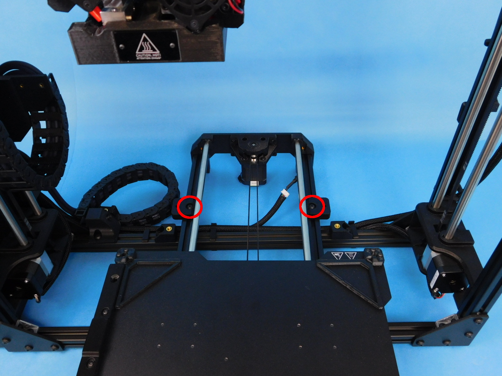
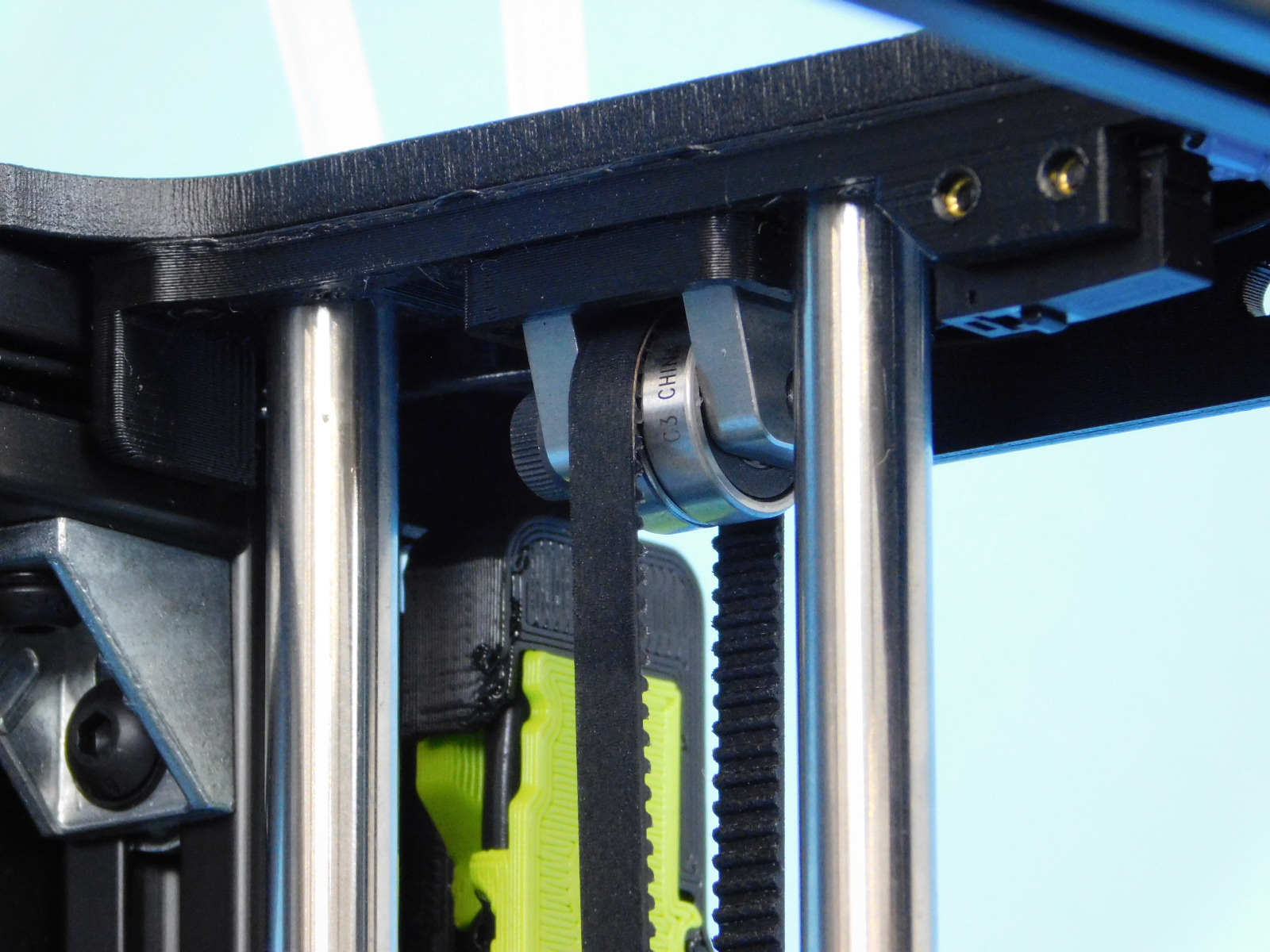
Move each axis through the entire range of motion while observing where the belt rides in each idler. The belt should not rub on any printed or machined parts.
The position of the Z axis belt in the idlers can be adjusted by use of the 2 set screws in the Z-Top plates behind and in front of the Z belt tension screw. If the belt is riding towards the front, tighten the set screw in front of the Z belt tension screw. If riding towards the rear, tighten the rear set screw.
X belt position can be slightly corrected by tightening one of the X belt tensioner screws tighter than the other and thus securing the belt at an angle; If riding towards the front, tighten the rear tensioner screw further than the front. If riding towards the rear, tighten the front tensioner screw further than the rear.

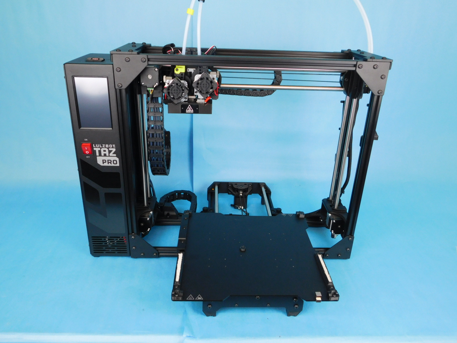
Final Assembly is now complete, check your work.
Place the completed final assembly on the rack of completed finals to be calibrated.