Open HardwareAssembly Instructions
Guides for installation and assembly of the LulzBot line of products made by FAME 3D LLC.
Guides for installation and assembly of the LulzBot line of products made by FAME 3D LLC.
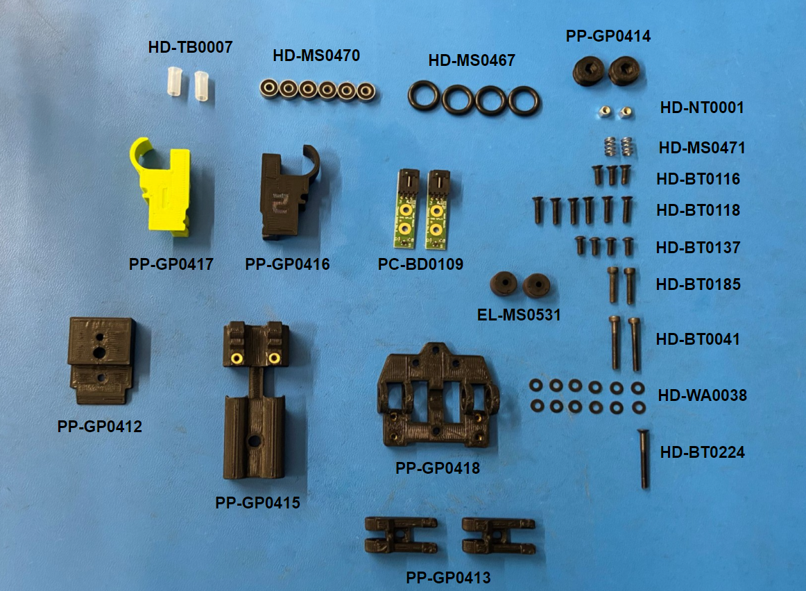
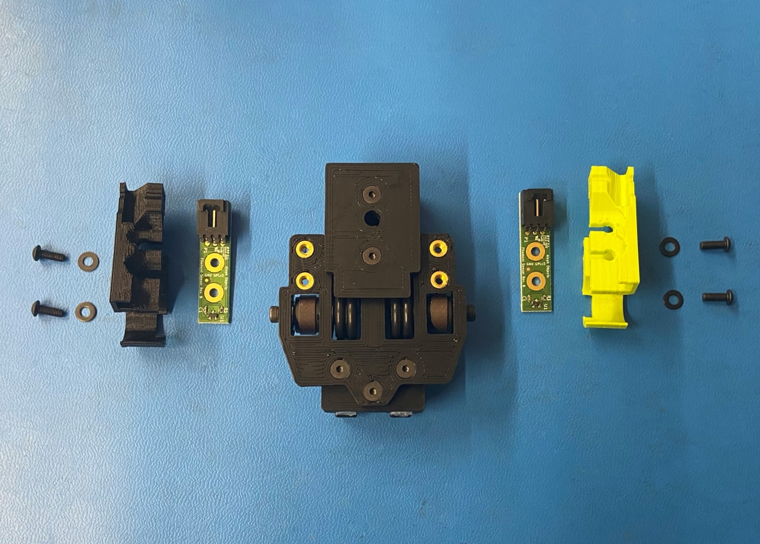
Assemble the materials needed for the [AS-PR0144] Filament Sensor Assembly
3x- [HD-BT0116] M3x10 FHCS
6x- [HD-BT0118] M3x14 FHCS,
4x- [HD-BT0137] M3x8 BHCS
2x- [HD-BT0185] M3x16 SHCS
1x- [HD-BT0224] M3x30 FHCS
2x- [HD-BT0041] M3x25 SHCS
2x- [HD-NT0001] M3 Nyloc Nut
12x- [HD-WA0038] M3 Washer
2x- [HD-MS0471] Round Compression Spring .22OD 21lbs/in D11450
2x- [PC-BD0109] Filament Sensor PCBA Rev B
1x- [PP-GP0416] Sensor Cover R
1x- [PP-GP0417] Sensor Cover L
2x- [EL-MS0531] G8 RADIAL MULTIPOLE RING - 1/2" 20 pole
4x- [HD-MS0467] Oil-Resistant Buna-N O-Ring 3 mm Wide, 11 mm ID
6x- [HD-MS0470] Two side Rubber Seal Bearing
2x- [PP-GP0414] Filament Wheel
1x- [PP-GP0418] Bearing Mount
1x- [PP-GP0412] Filament Sensor Mount with Inserts
2x- [HD-TB0007] 9.5mm Feed Tube
1x- [PP-GP0415] Dual Tube Clamp with Inserts
2x- [PP-GP0413] Sensor Idler with Inserts
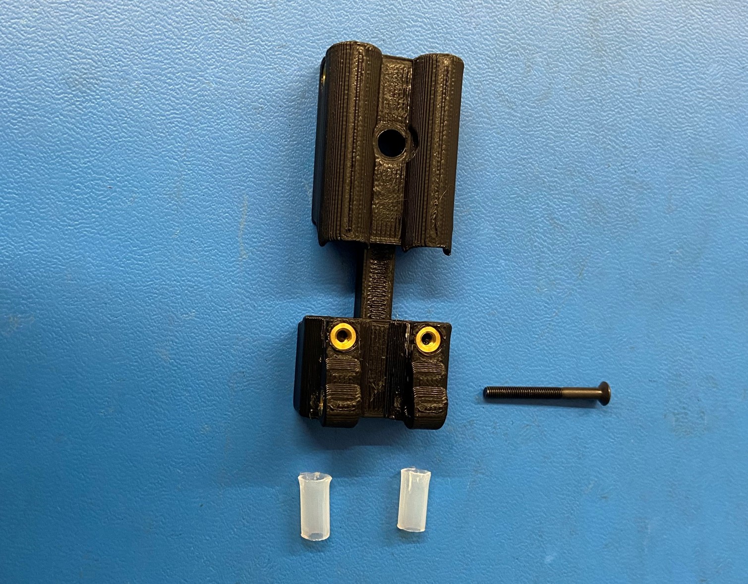
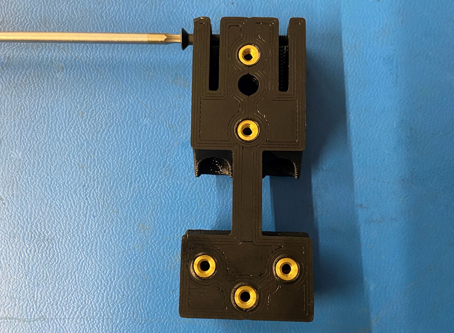
Cut out 2x 9.5mm Feed tubes [HD-TB0007] and slide them into the Dual tube clamp with inserts [PP-GP0412].
Fasten the clamp end of the dual tube clamp using an M3X30mm FHCS [HD-BT0224].
Do not tighten, this will serve to hold the filament tubes firmly in place.

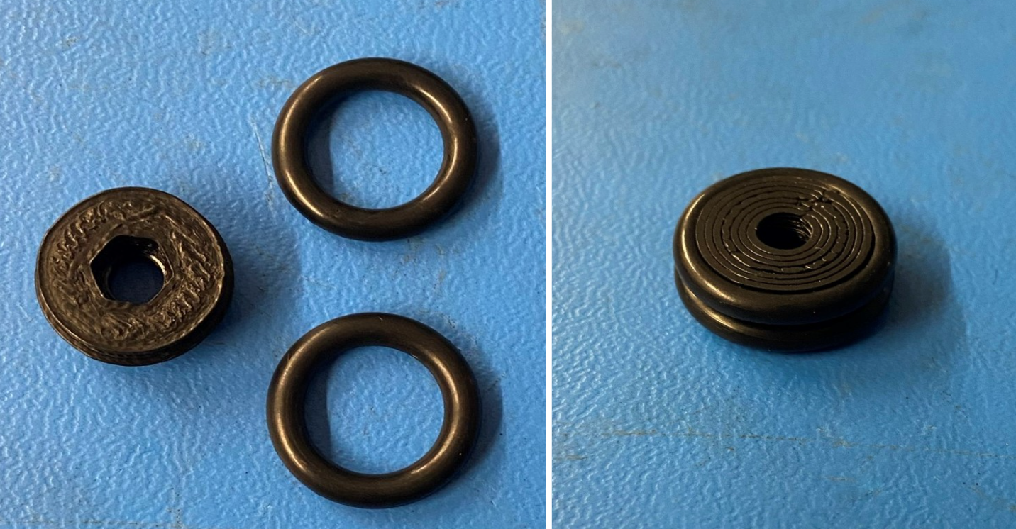
Take the Filament Wheel [PP-GP0418] and install 2x O-rings [HD-MS0467] into the grooves
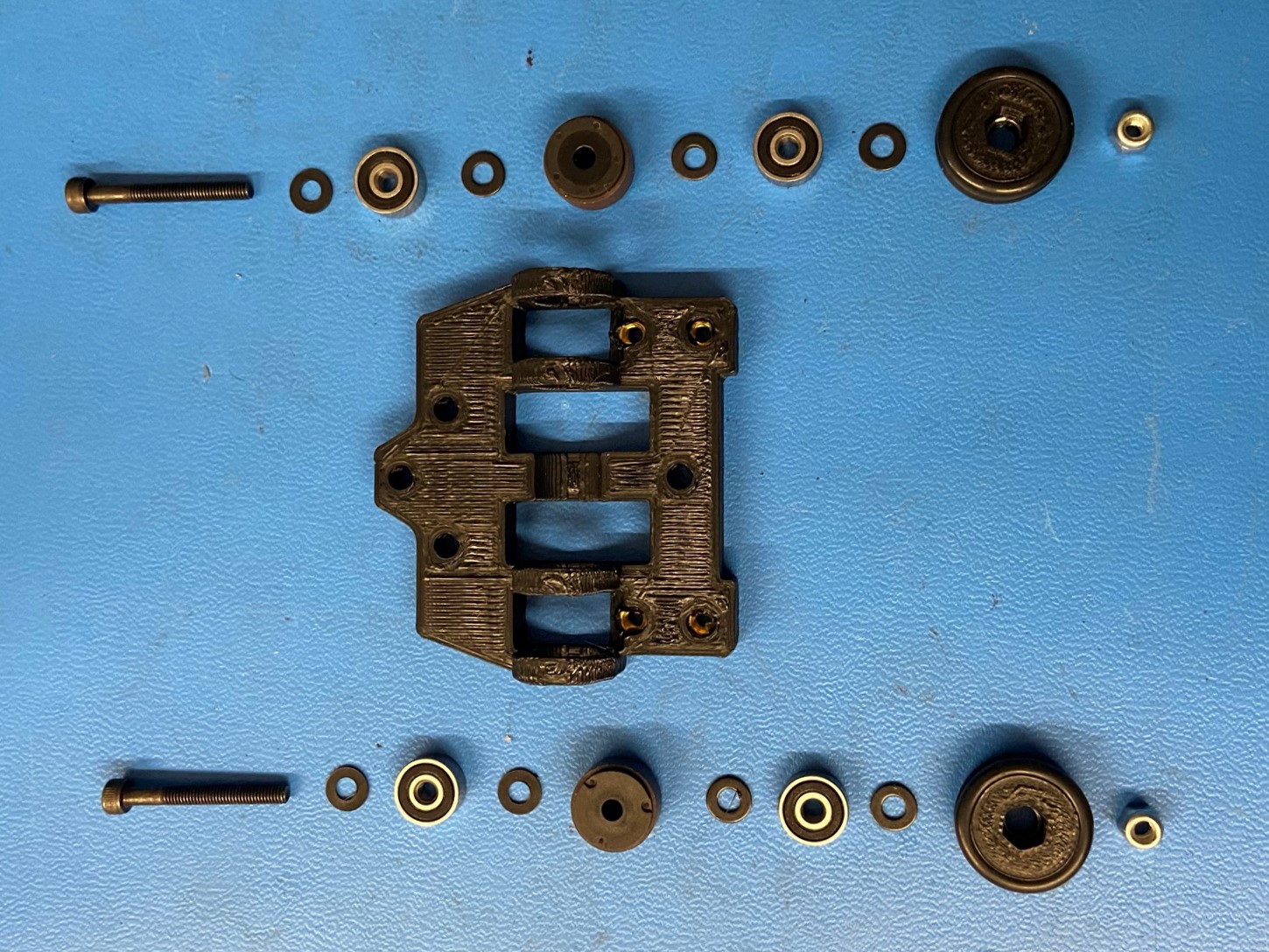
Take an M3X25 SHCS [HD-BT0041], sliding on an M3 washer [HD-WA0038], and rubber sealed bearing [HD-MS0470], and followed up by another washer [HD-WA0038]. Place 1x Multipole Ring [El-MS0531] between the two rings on the Bearing Mount [PP-GP0414]. Then slide the bolt with the washer and bearings through the multipole ring.
Then place another washer [HD-WA0038] and then slide a rubber sealed bearing [HD-MS0470] into the second ring of the mount. Follow this up with another washer [HD-WA0038].
Place an M3 Nyloc Nut [HD-NT0001] into the provided slot on the assembly filament wheel with the nylon side facing out.
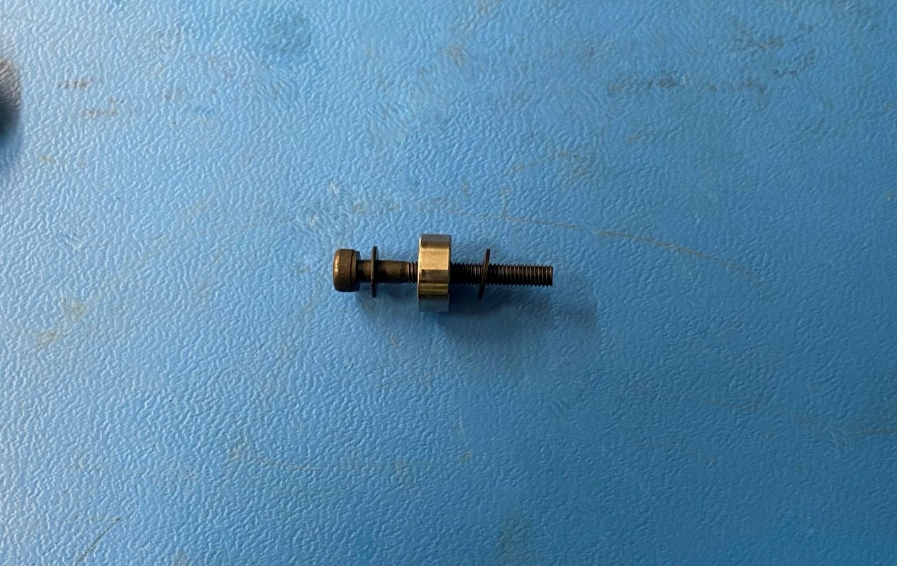
Slide it on to the stack and fasten the screw until it sits tight with no side to side movement.
Repeat these steps for the other side.
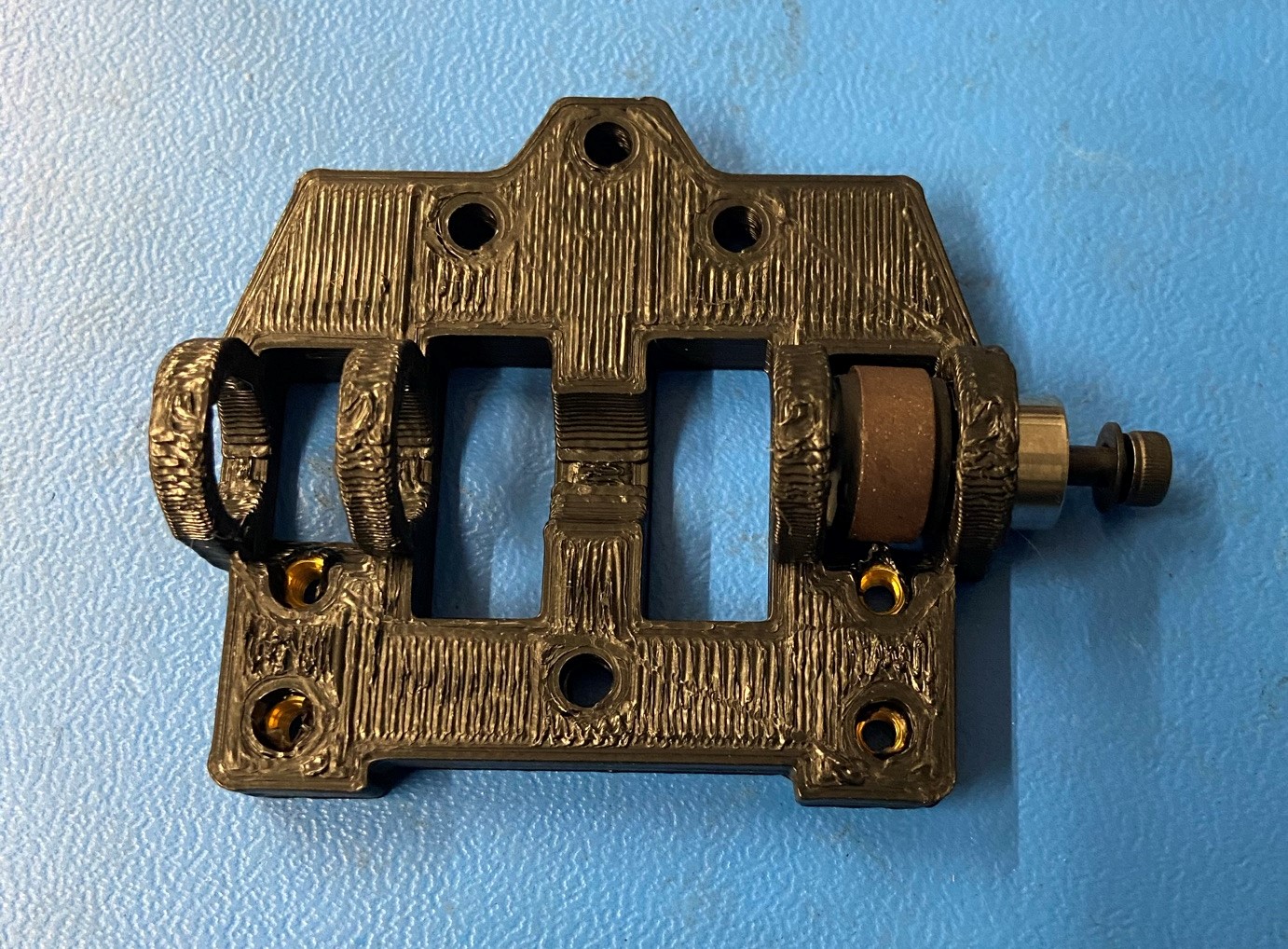

Fasten the encoder wheel on to the Dual Tube Clamp using 3x M3x10mm FHCS [HD-BT0116].
Torque to 5in*lbs
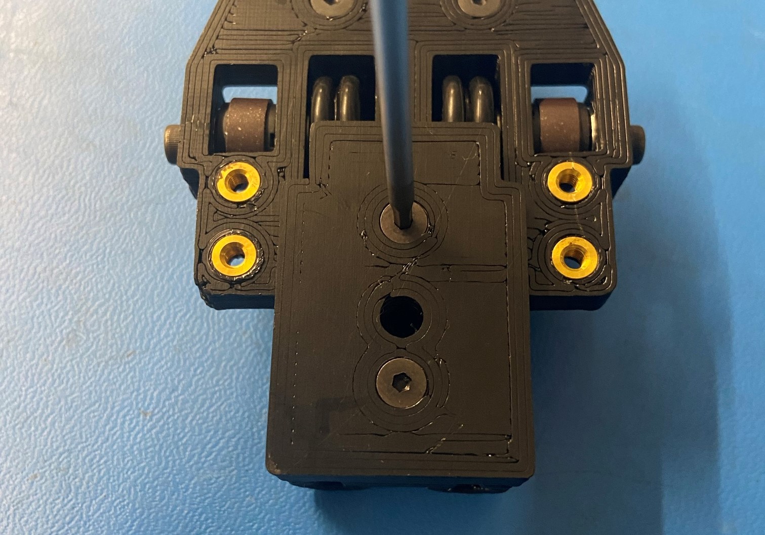
Fasten the Filament Sensor Mount w/ Inserts [PP-GP0412] to the Dual Tube Clamp using 2x M3x14 FHCS [HD-BT0118], making sure that the slant of the mount is fitting over the encoder wheel.
Torque to 5in*lbs

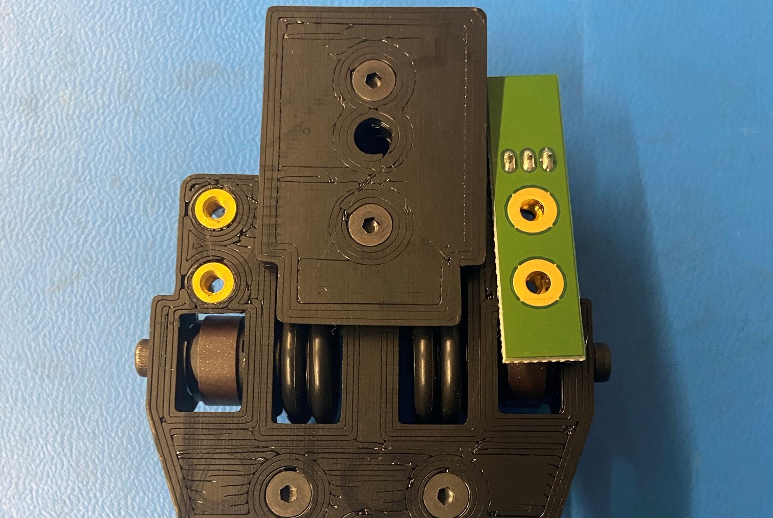
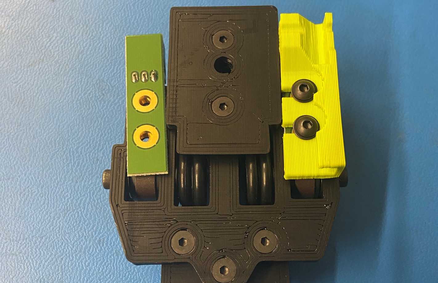
Place the Filament Sensor [PC-BD0109] on the two brass inserts on the left side of the filament sensor mount make sure the connector on the filament sensor is facing away from the multipole rings.
Slide the Sensor Cover L [PP-GP0417] over top of the filament sensor before fastening it down with 2x M3x8 BHCS [HD-BT0137] with washers [HD-WA0038].
Push the filament sensor board towards the bottom of the assembly before tightening
Torque to 3in*lbs
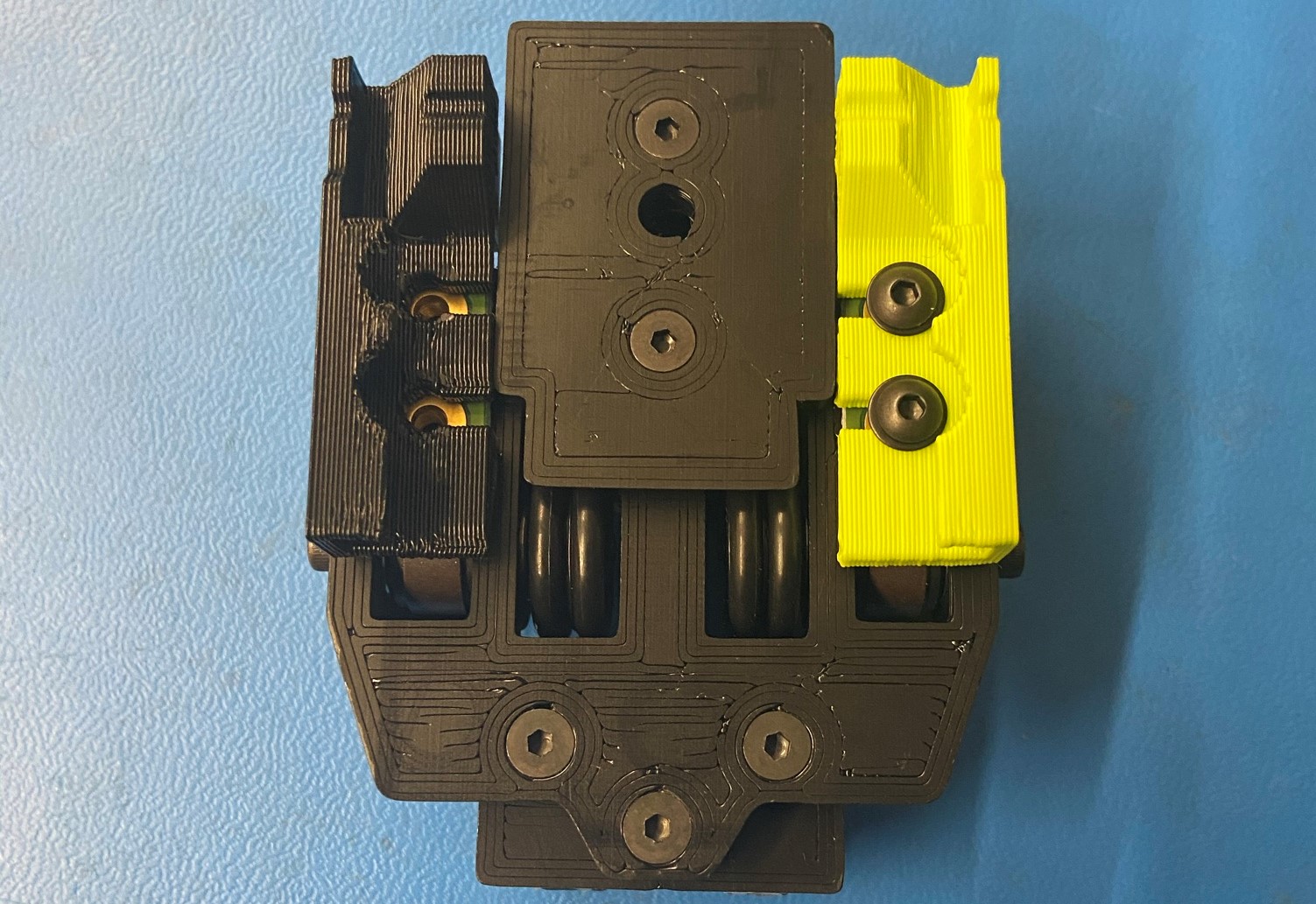
Repeat this for the right side
Place the Filament Sensor [PC-BD0109] on the two brass inserts on the right side of the filament sensor mount make sure the connector on the filament sensor is facing away from the multipole rings.
Slide the Sensor Cover R [PP-GP0416] over top of the sensor board before fastening it down with 2x M3x8 BHCS [HD-BT0137] with washers [HD-WA0038].
Push the filament sensor board towards the bottom of the assembly before tightening
Torque to 3in*lbs
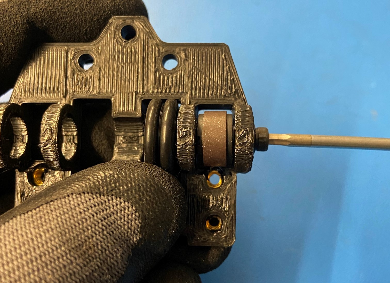
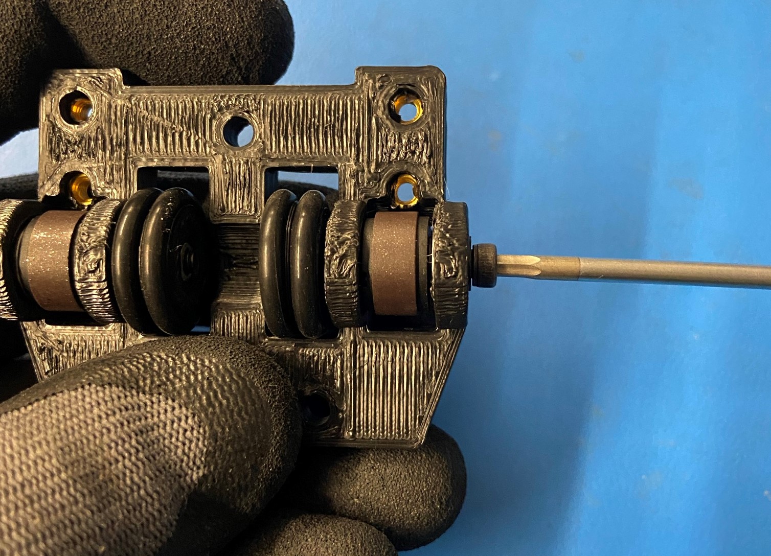
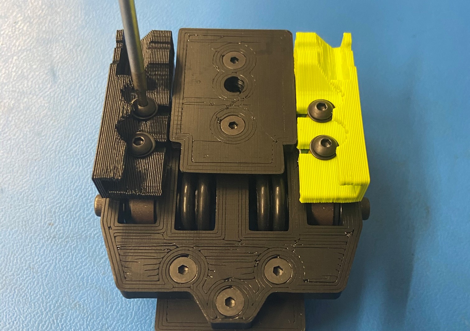
Turn the encoder through several rotations to make sure that it does not rub on the filament sensor board.

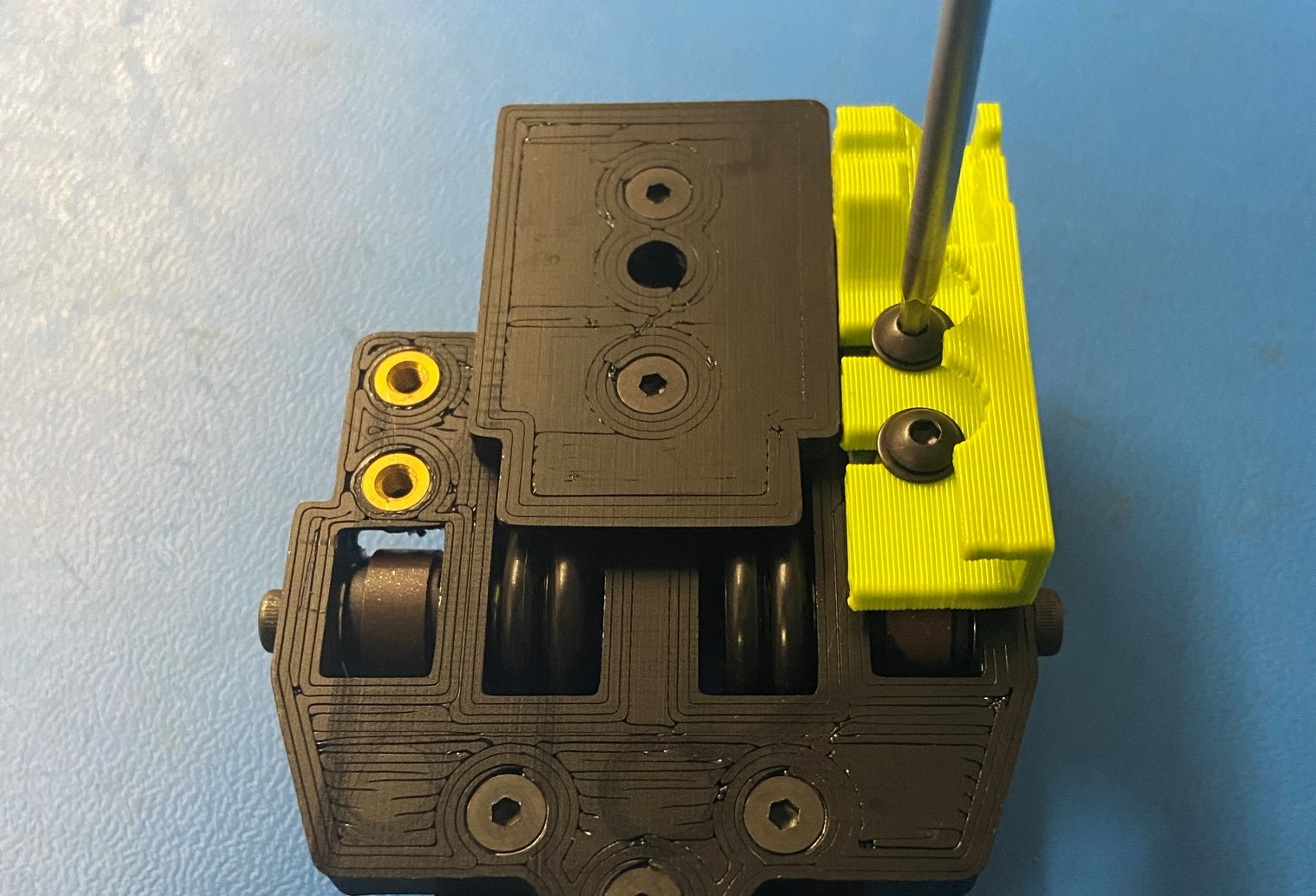
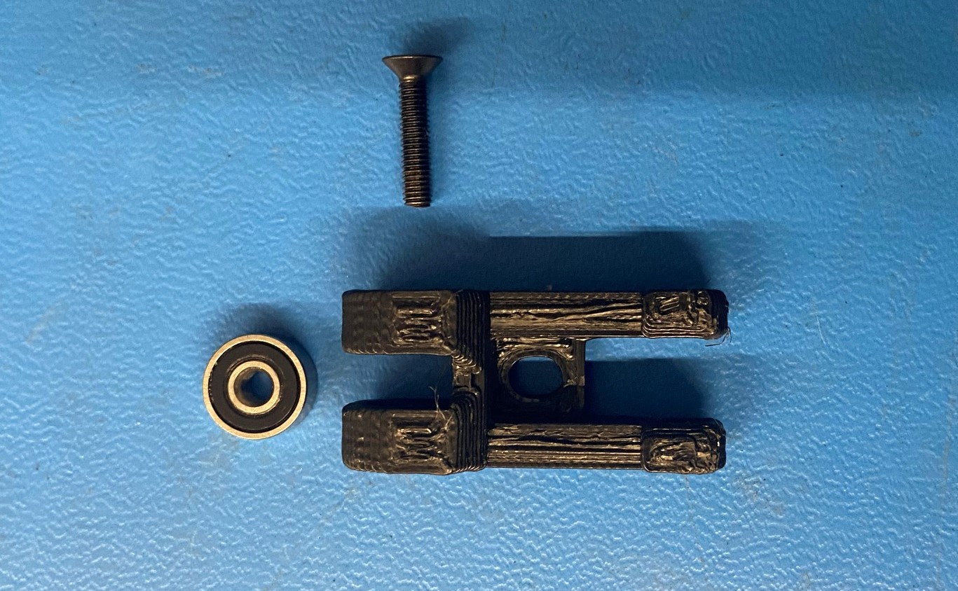
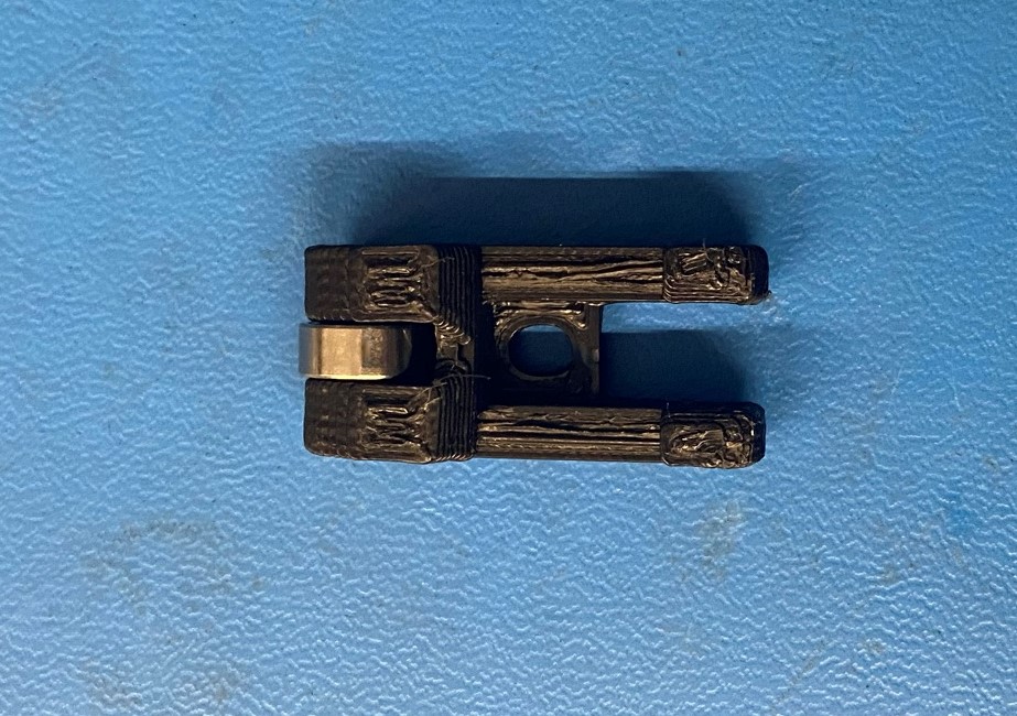
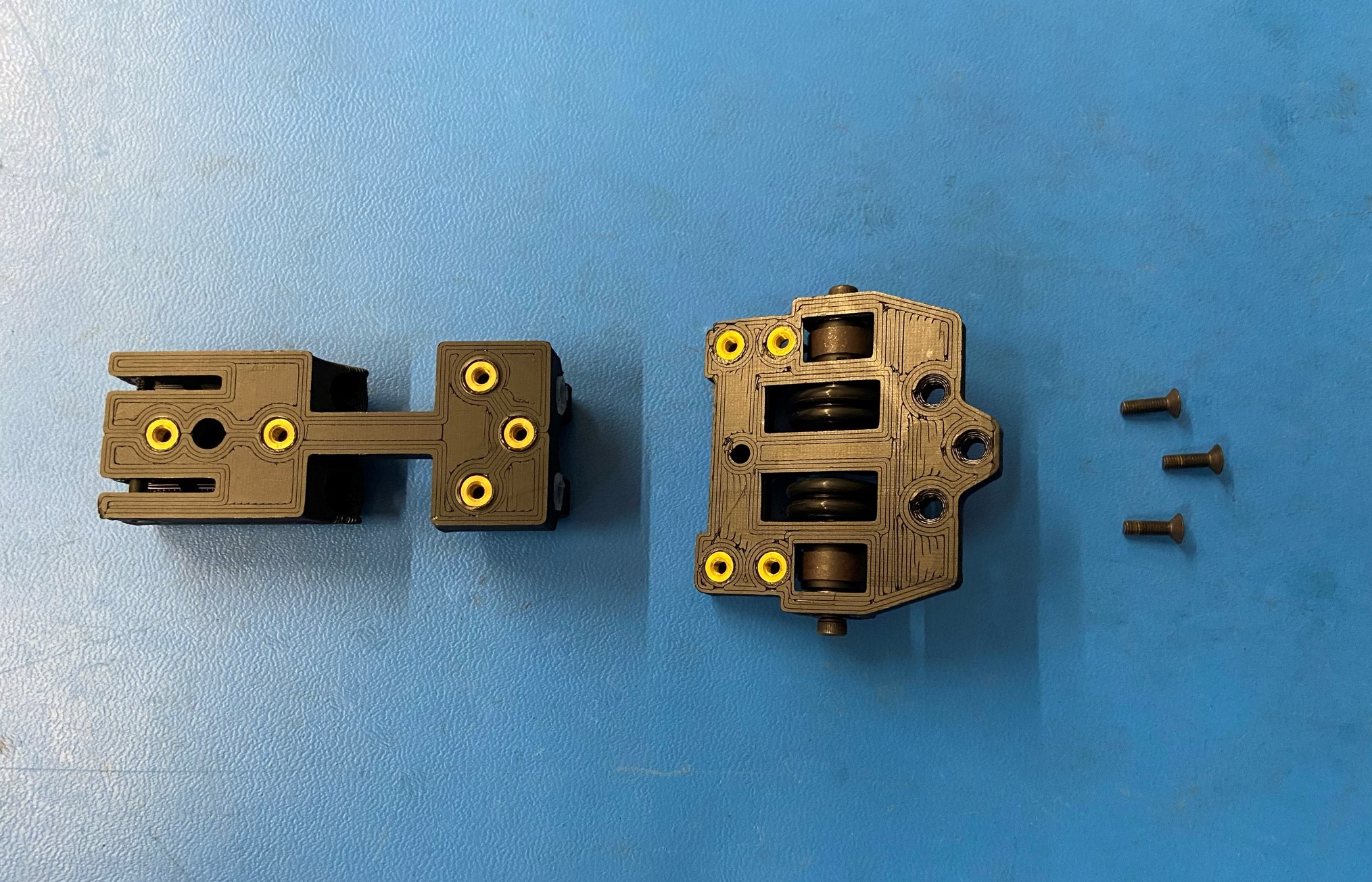
Fasten the rubber sealed bearing [HD-MS0470] to the Sensor Idler w/ Inserts [PP-GP0413] using an M3x14 FHCS [HD-BT0118].
Torque to 3in*lbs
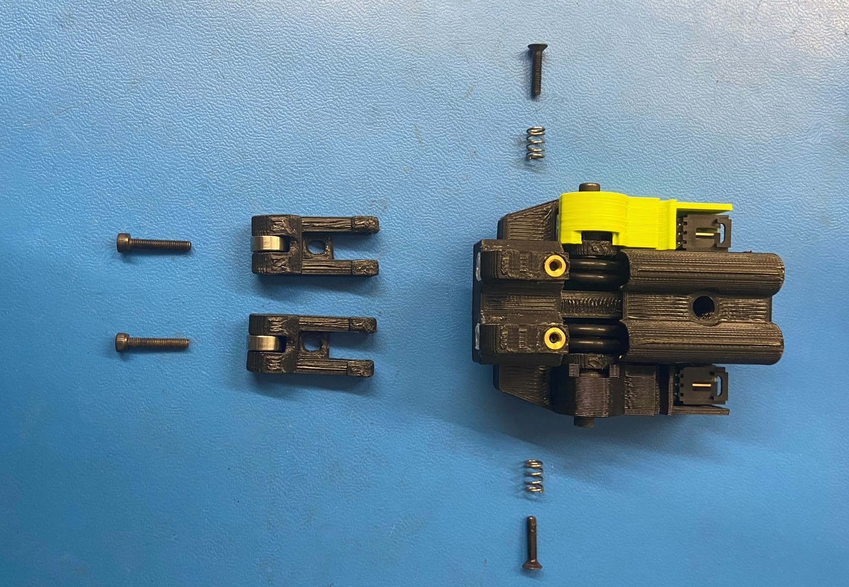
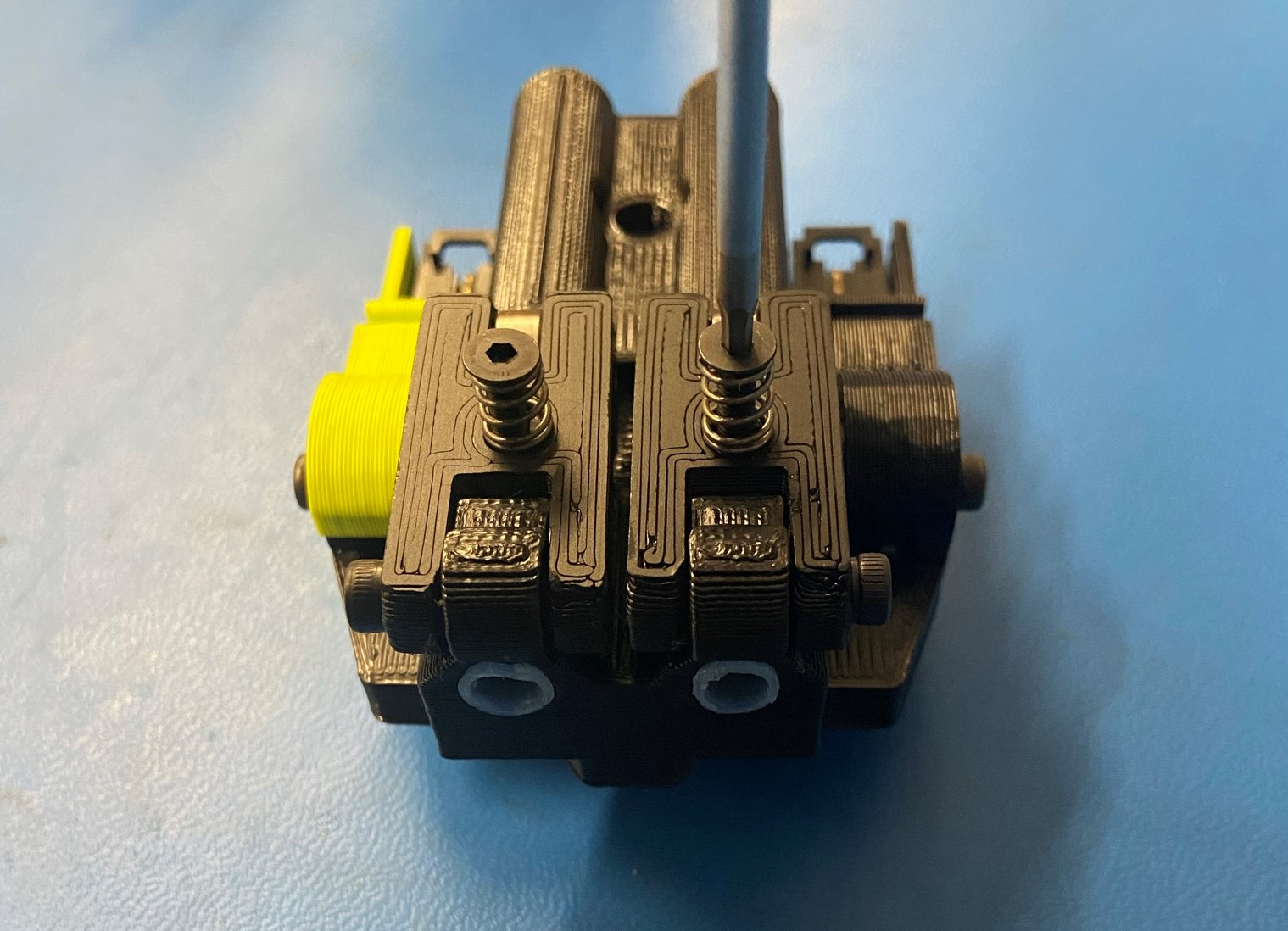
Fasten the sensor idler to the filament sensor assembly with an M3x16 SHCS [HD-BT0185] from the outside left/right.
Tighten until screw head rests against printed idler; too much tension will prevent the idler from moving properly.
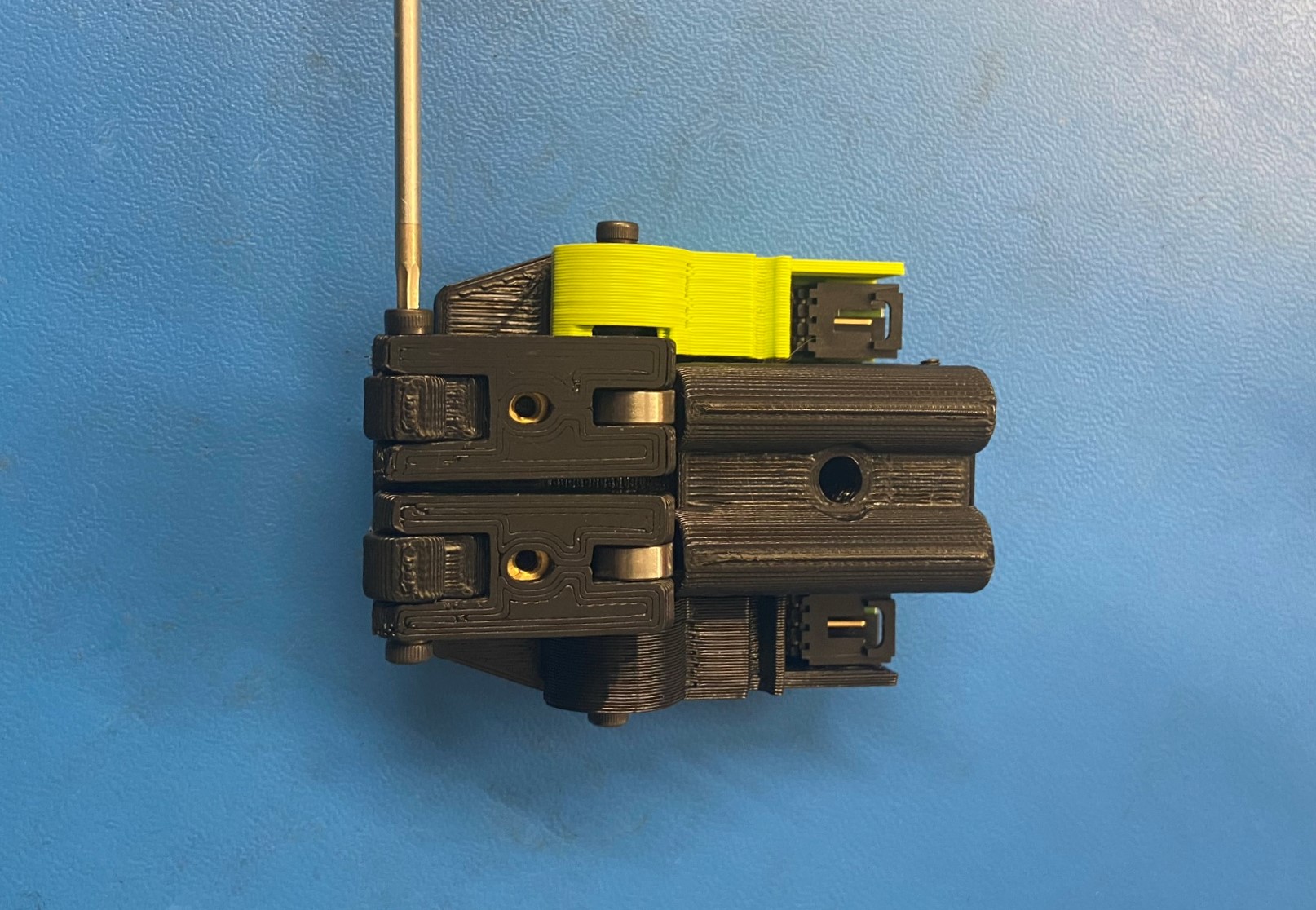
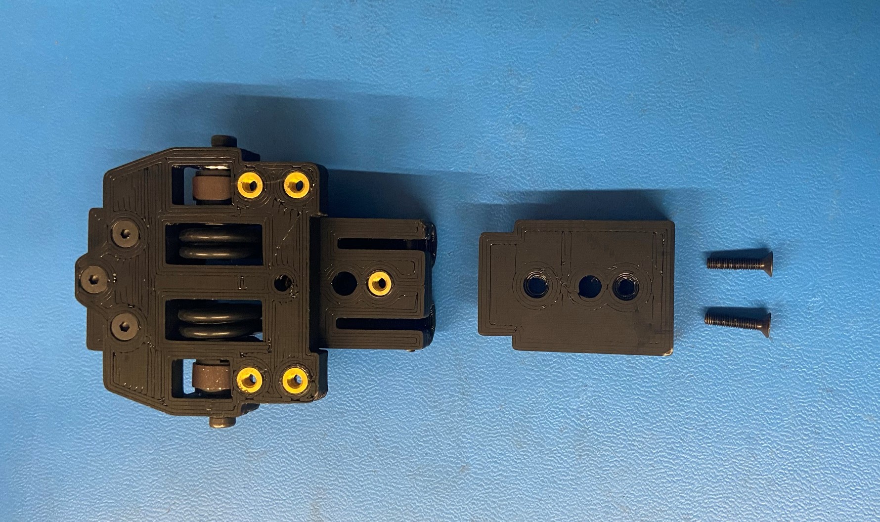
Slide one Round Compression Spring [HD-MS0471] onto an M3x14 FHCS [HD-BT0118]
Thread one through the front of each Filament Idler (2 total) and into the insert behind it.
This should not be tightened all the way.