Open HardwareAssembly Instructions
Guides for installation and assembly of the LulzBot line of products made by FAME 3D LLC.
Guides for installation and assembly of the LulzBot line of products made by FAME 3D LLC.
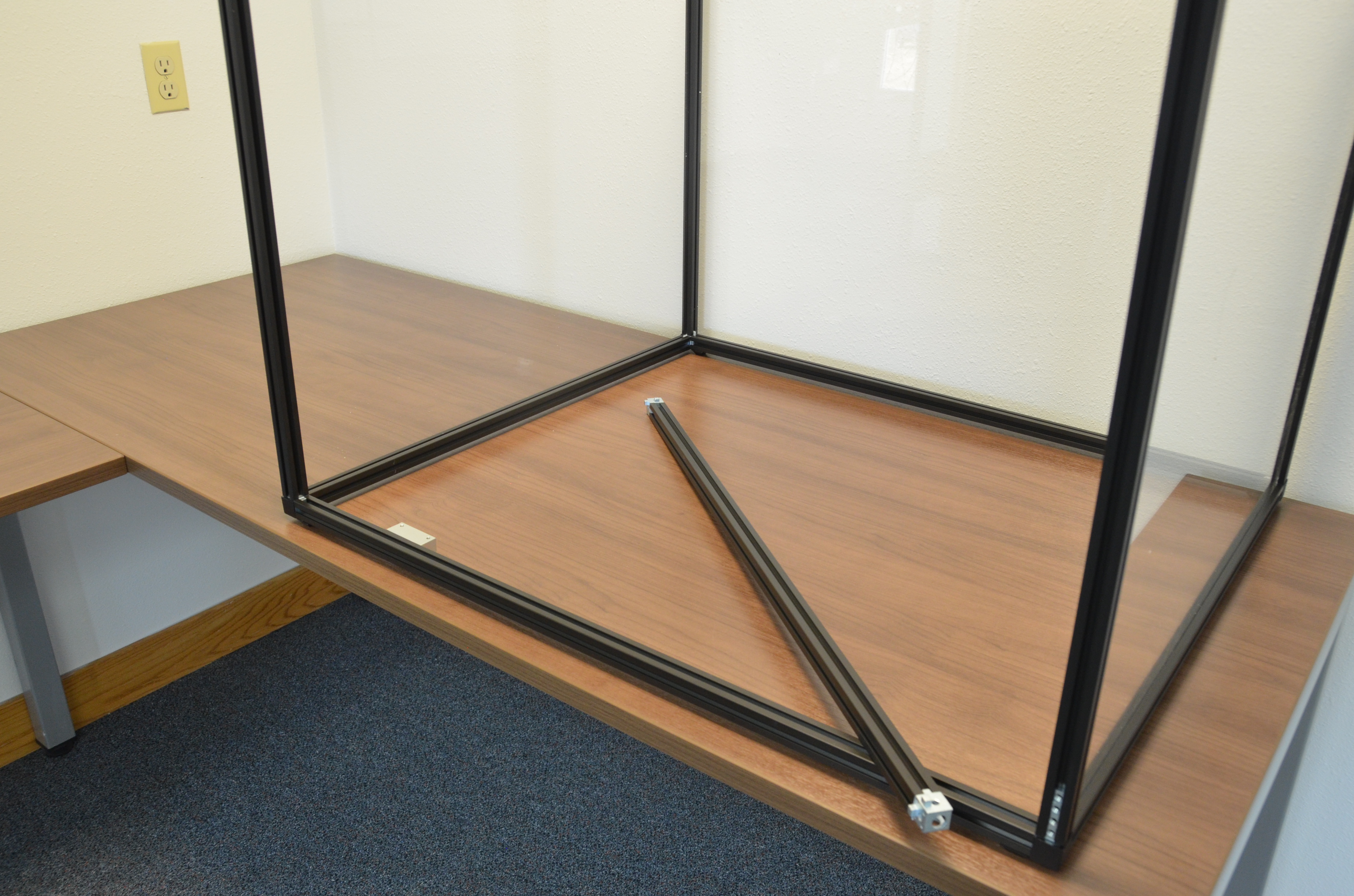
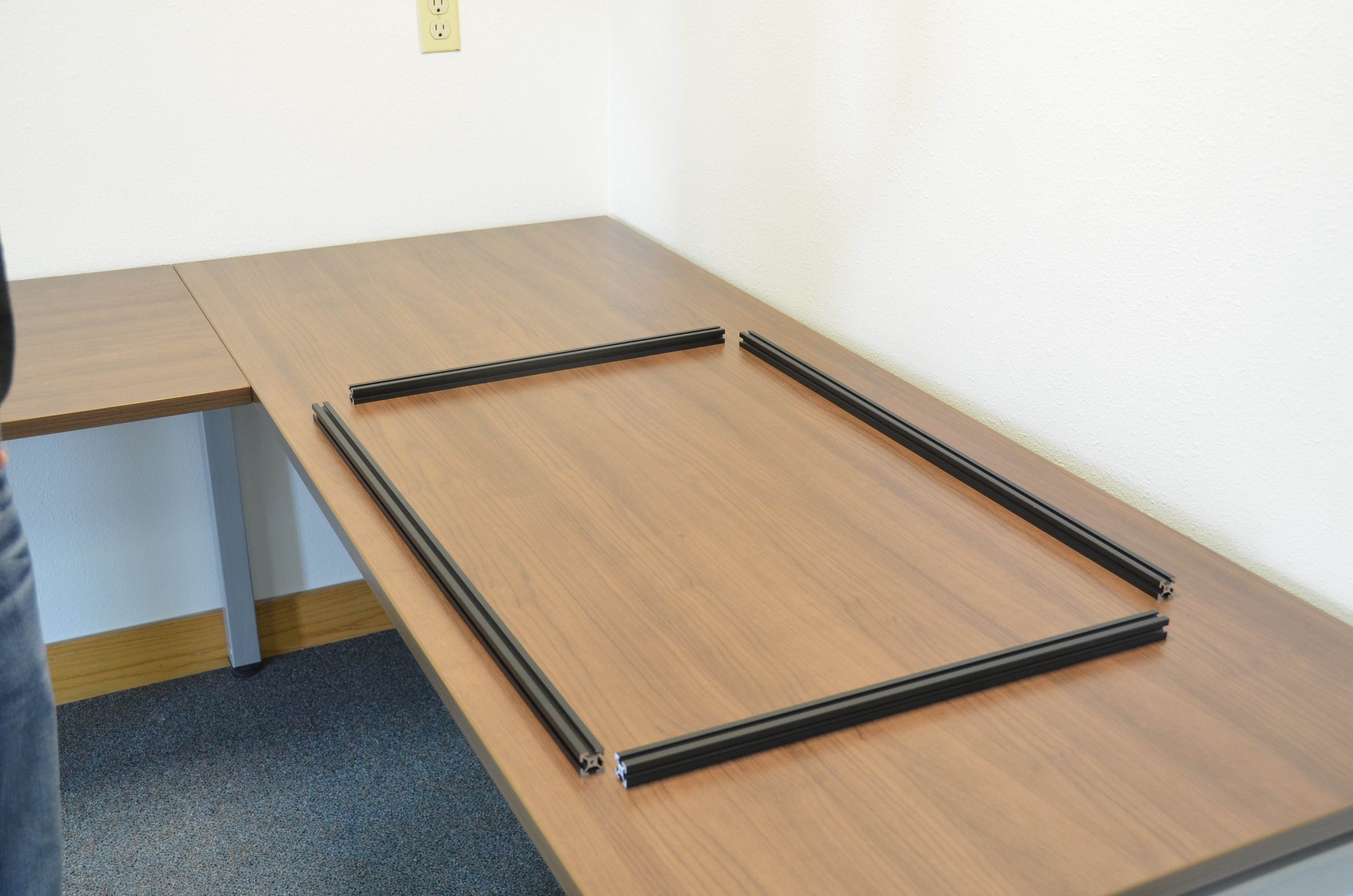
Lay out the base
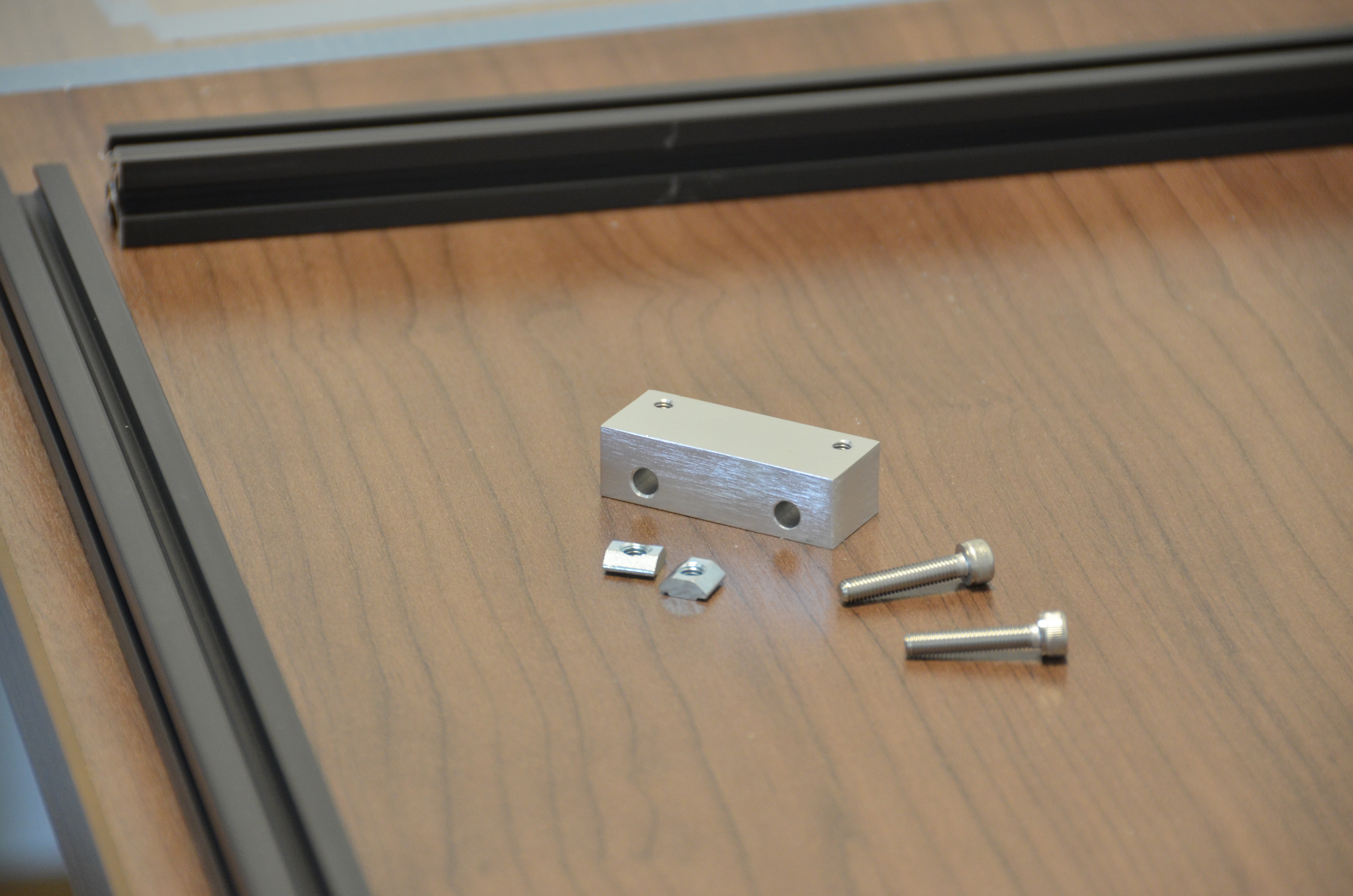
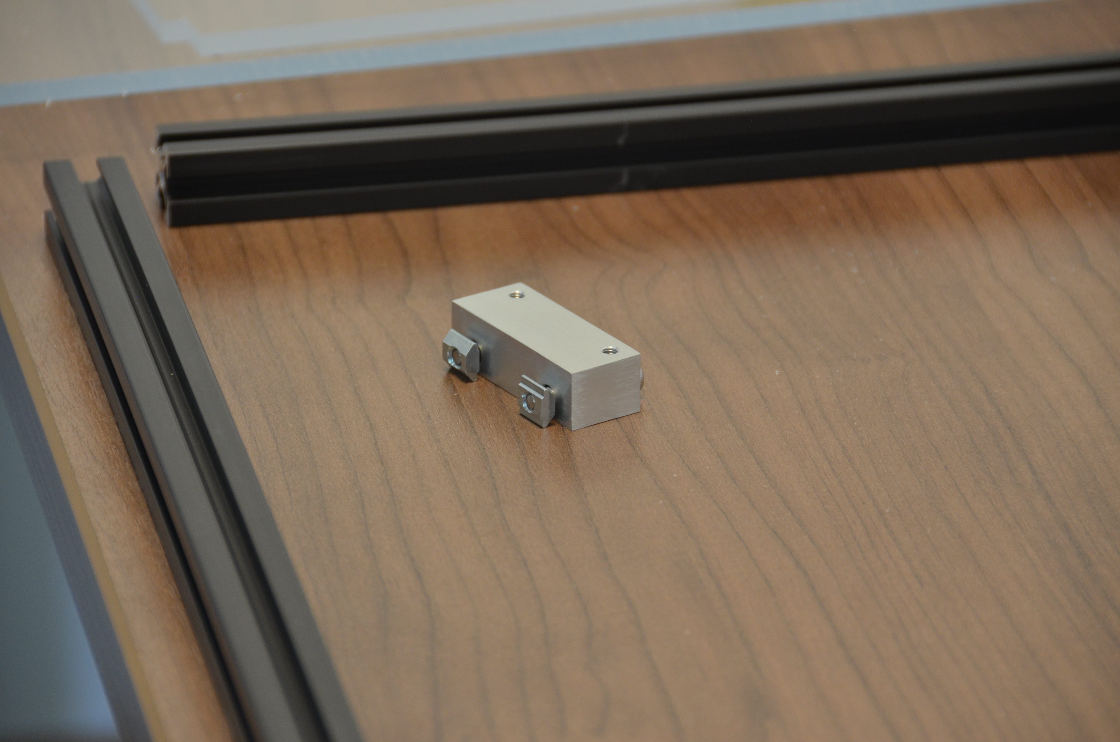
Assemble the Door Magnet Mount using the aluminum mounting block, 2 T Nuts and the 24mm M5 Socket Head screws.
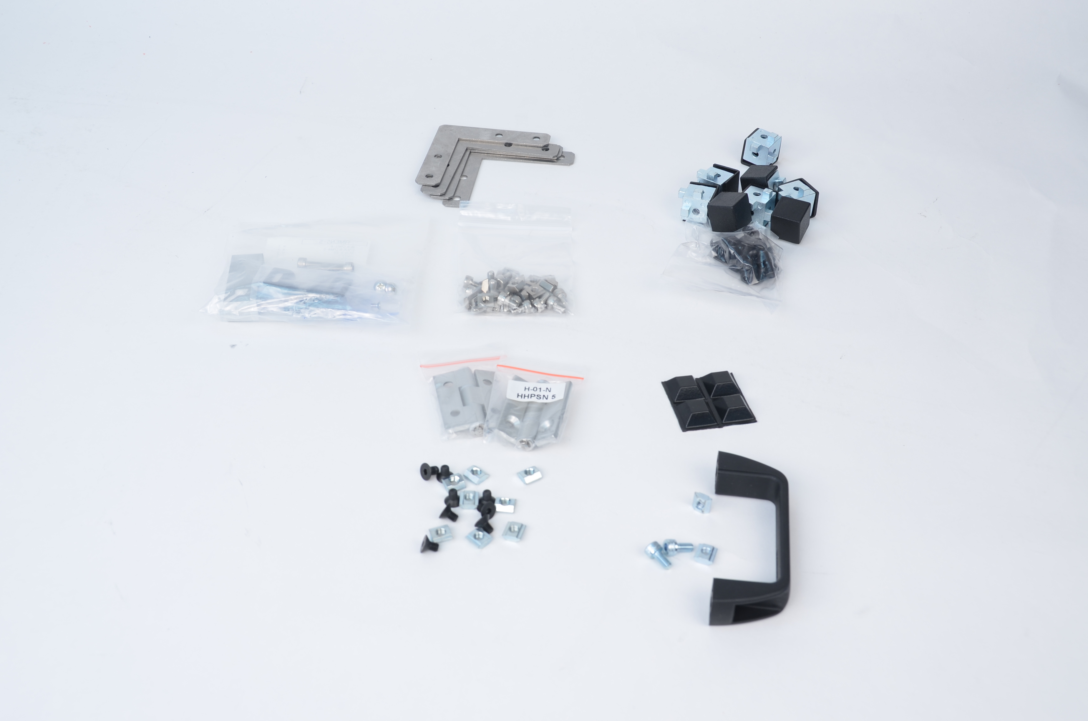
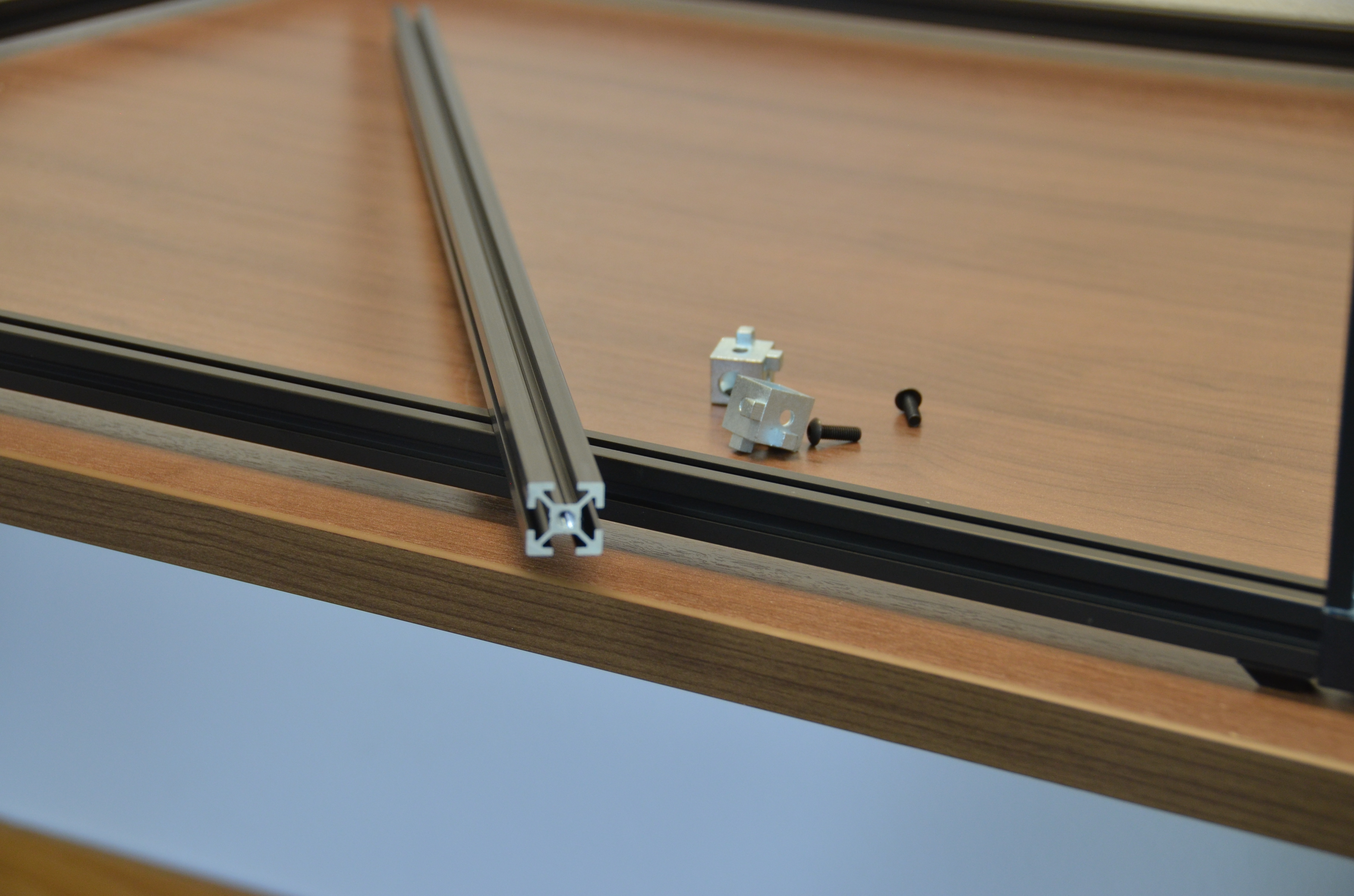
Use the followiing items to assemble the base:
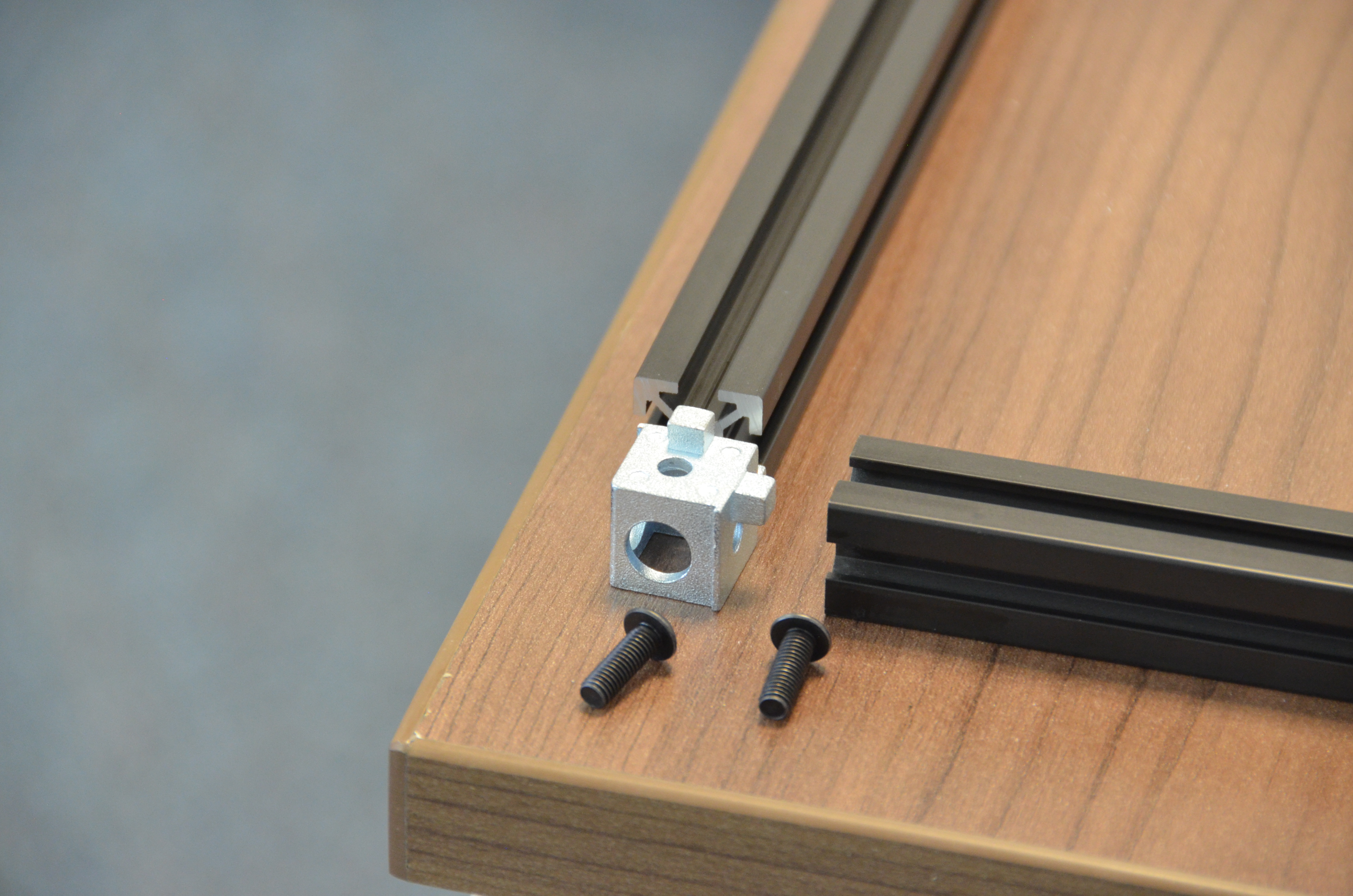
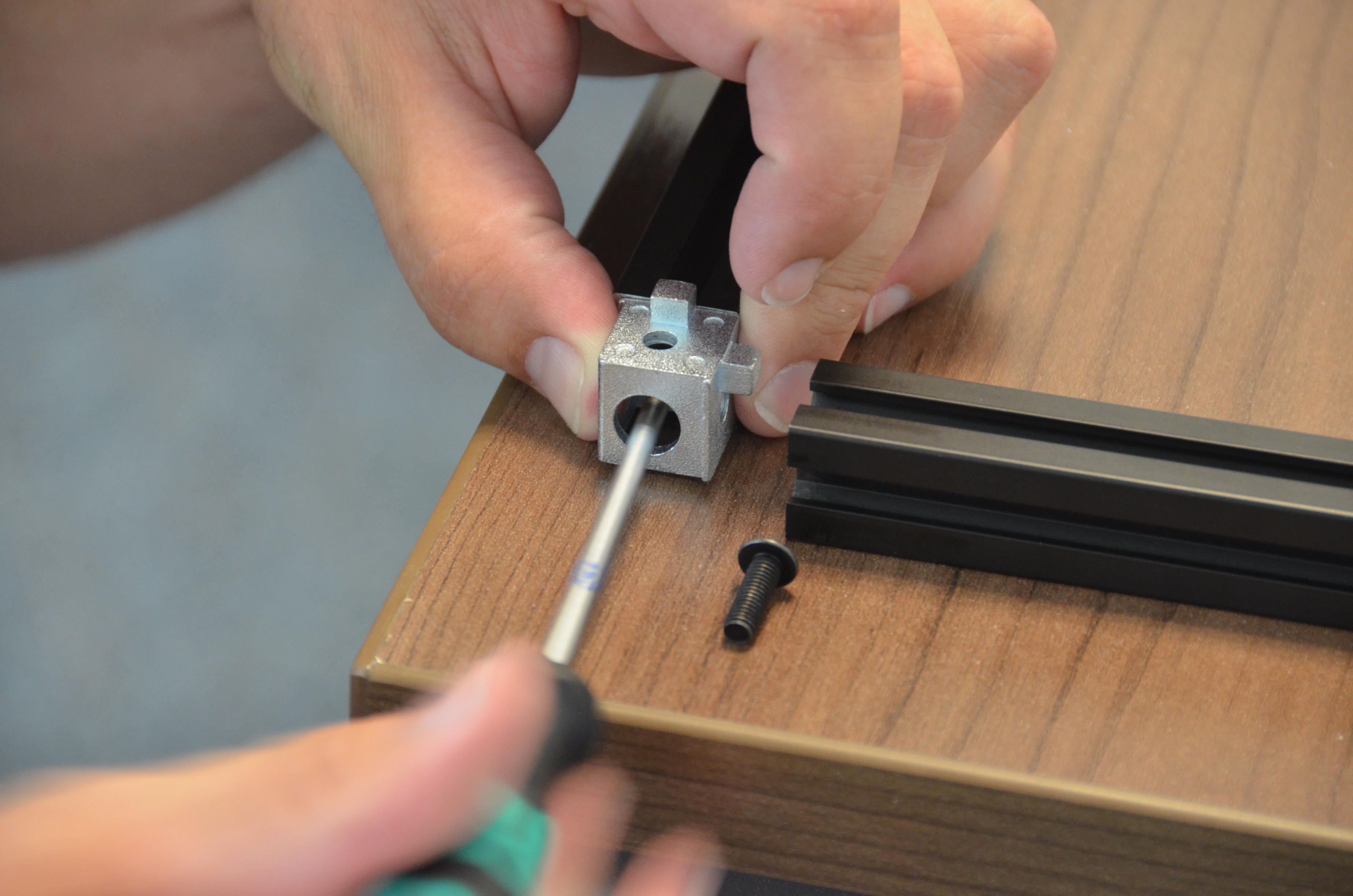
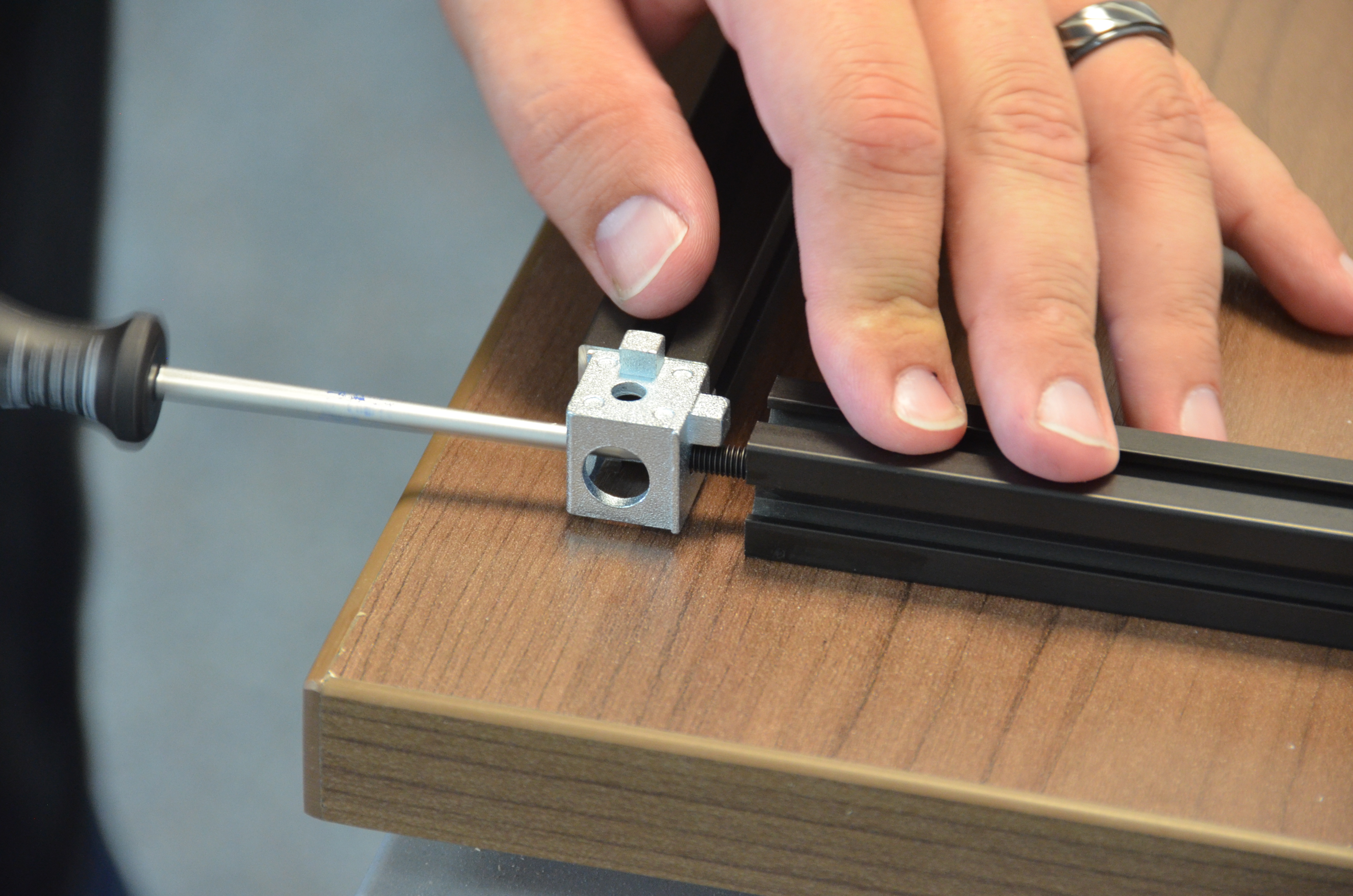
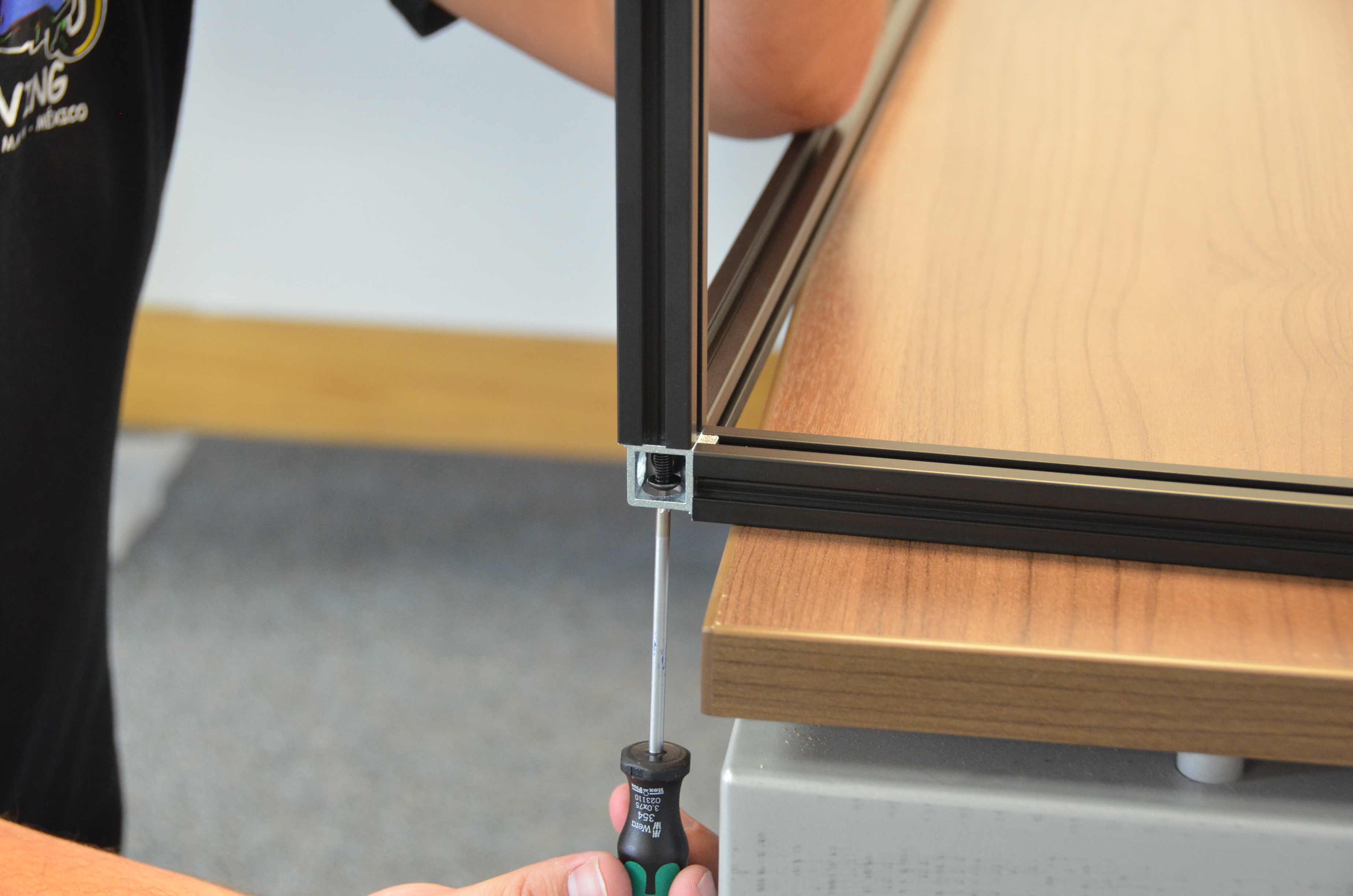
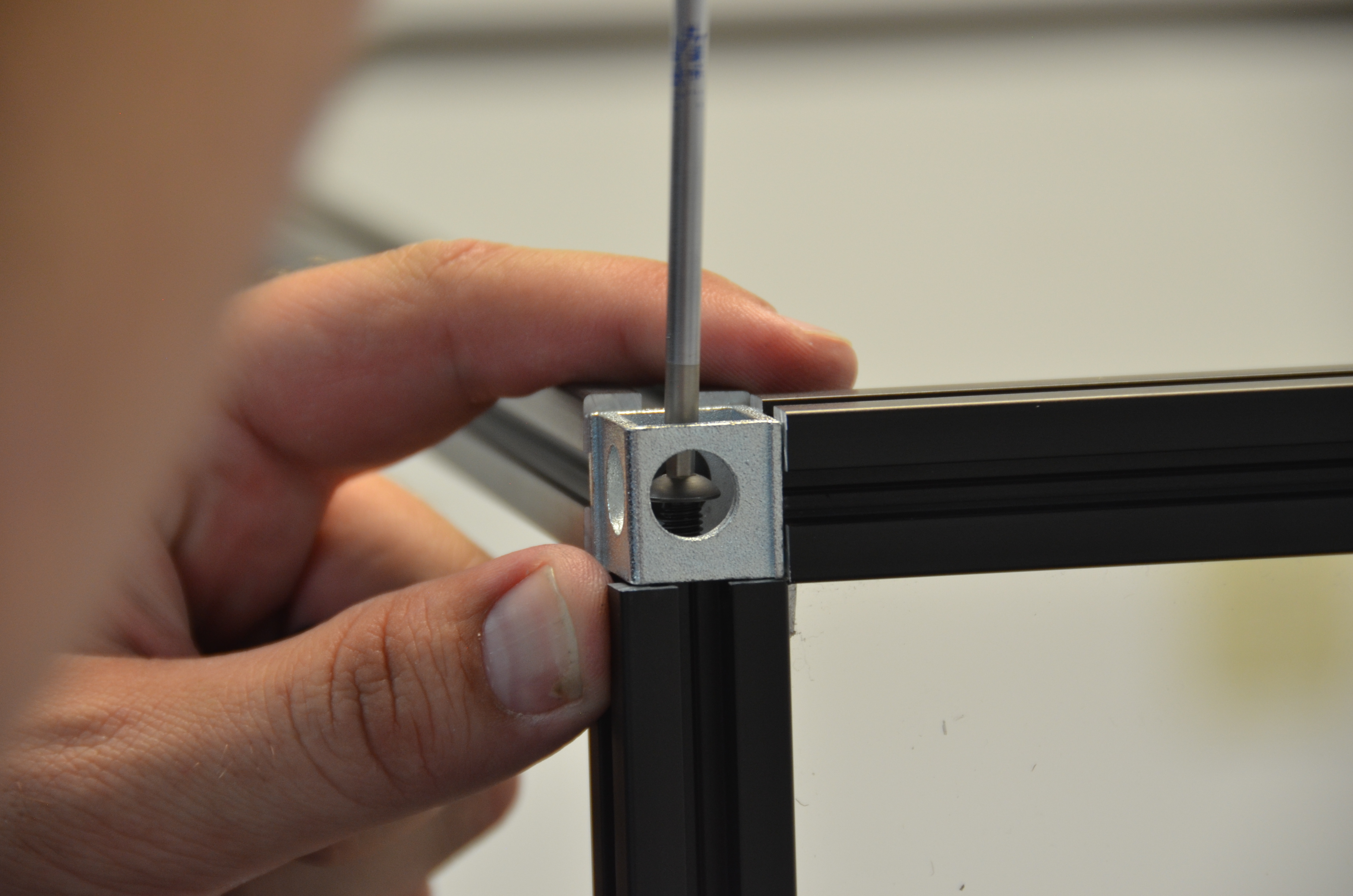
Attach the corner connector to the extrusion, using one 15mm M5 button cap screw.
Repeat for the other extrusion, using another 15mm M5 button cap screw.
Repeat for the other three corners.

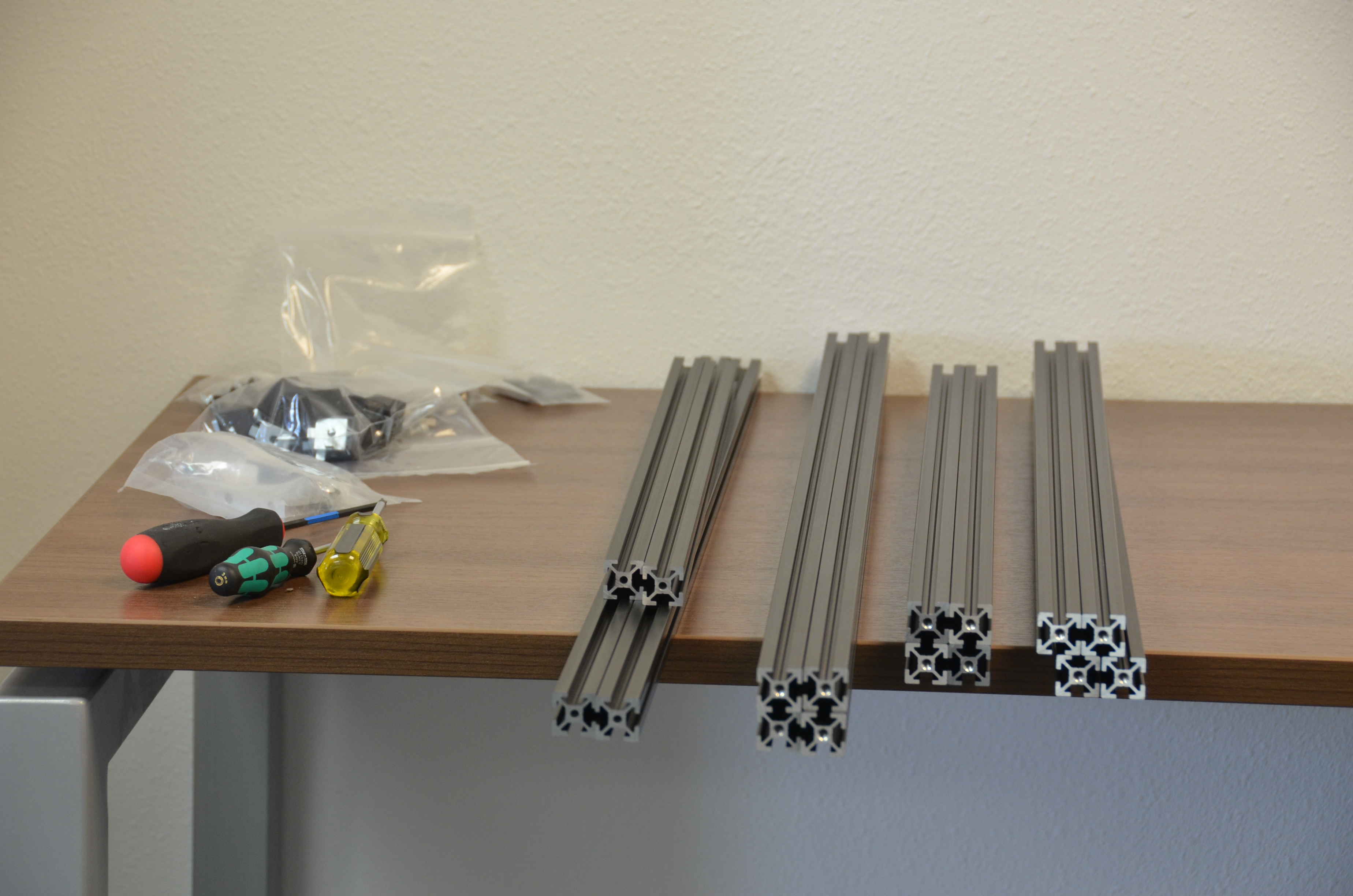
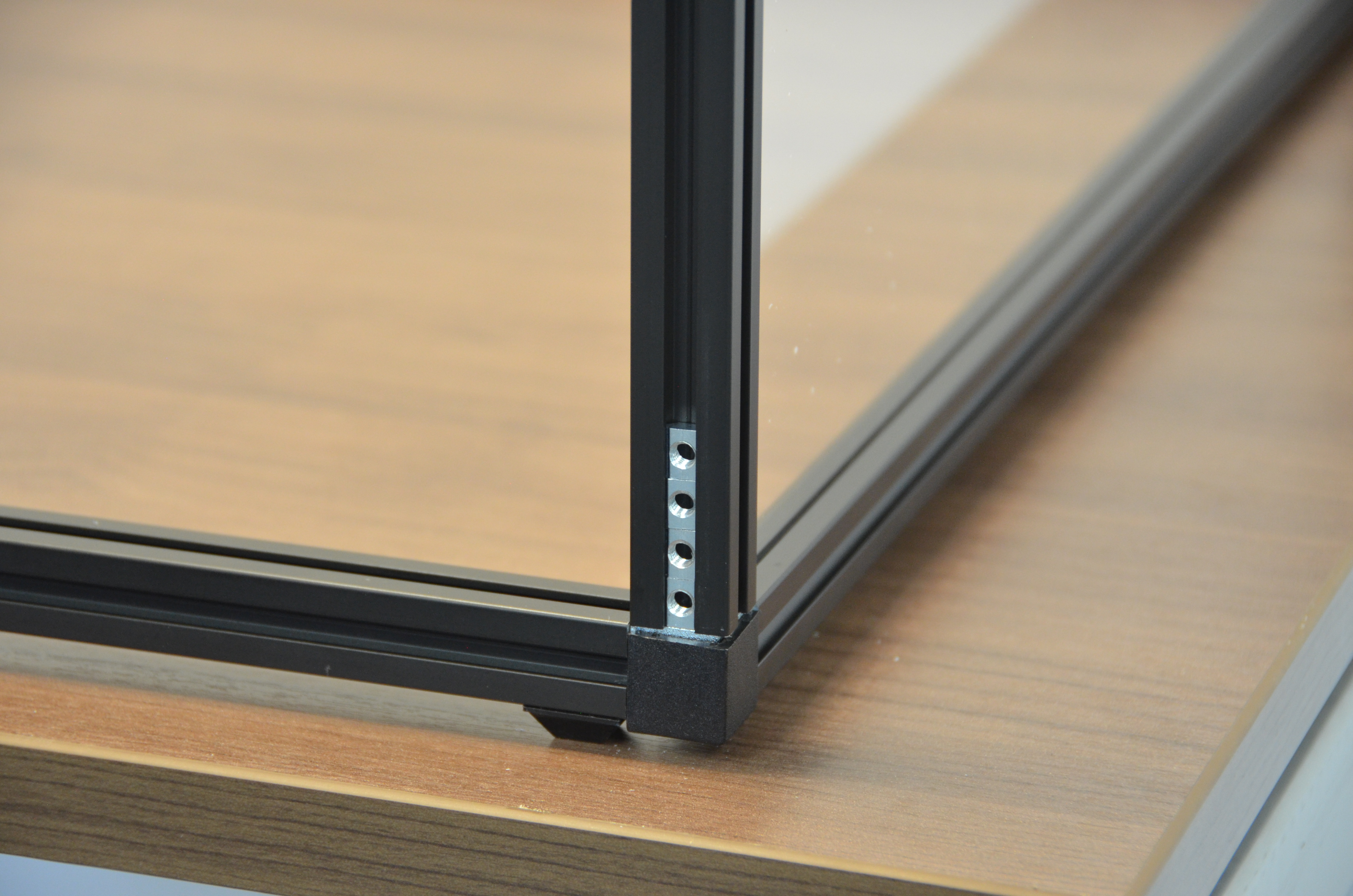
Mount the 4 Aluminum Extrusion 20mm x 20mm x 580mm uprights using 4 15mm M5 button cap screws onto the base.
After mounting all 4 uprights, flip over the assembled base, peel off the adhesive backing on the 4 square bumpers and mount them as feet.
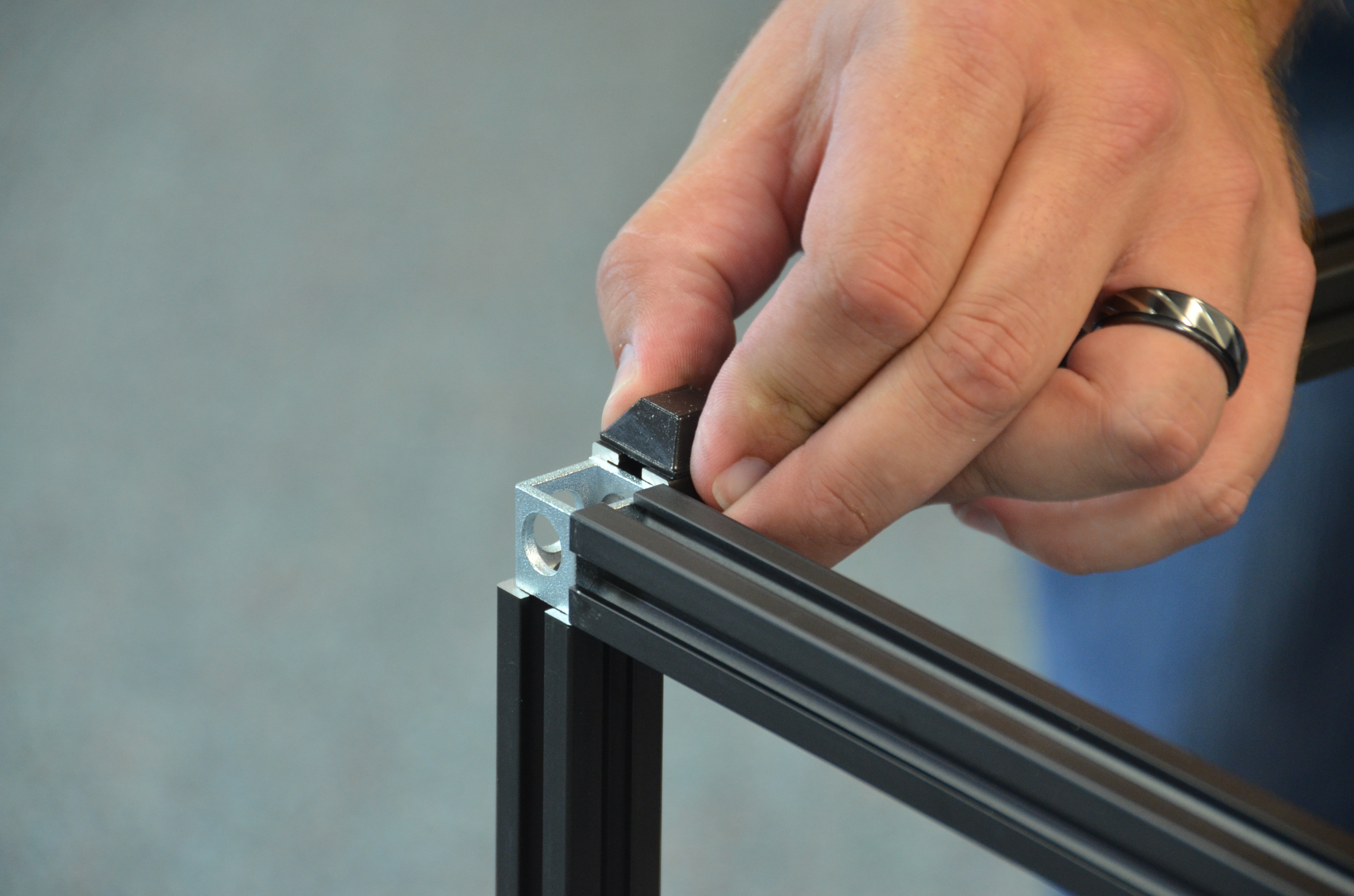
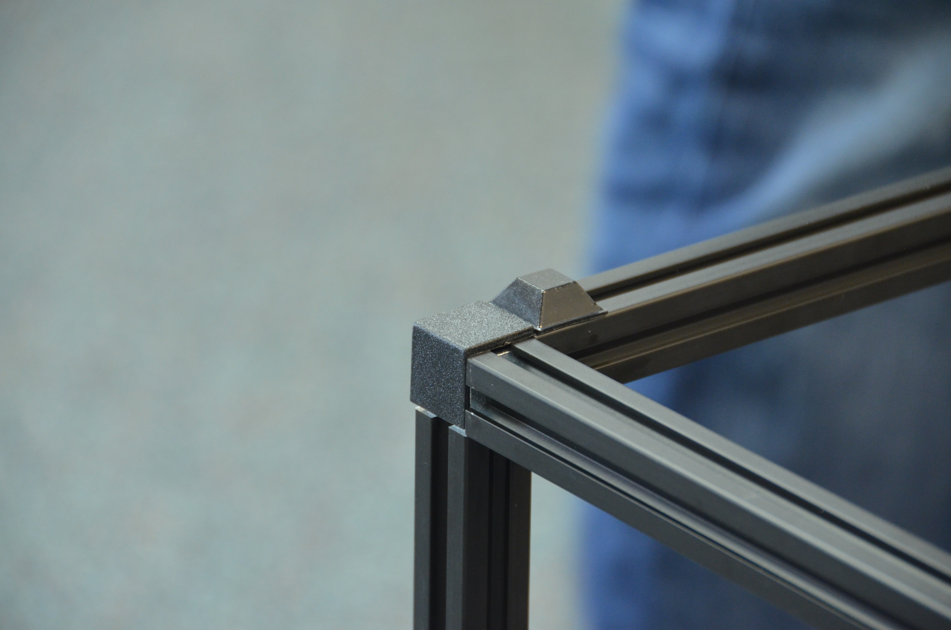
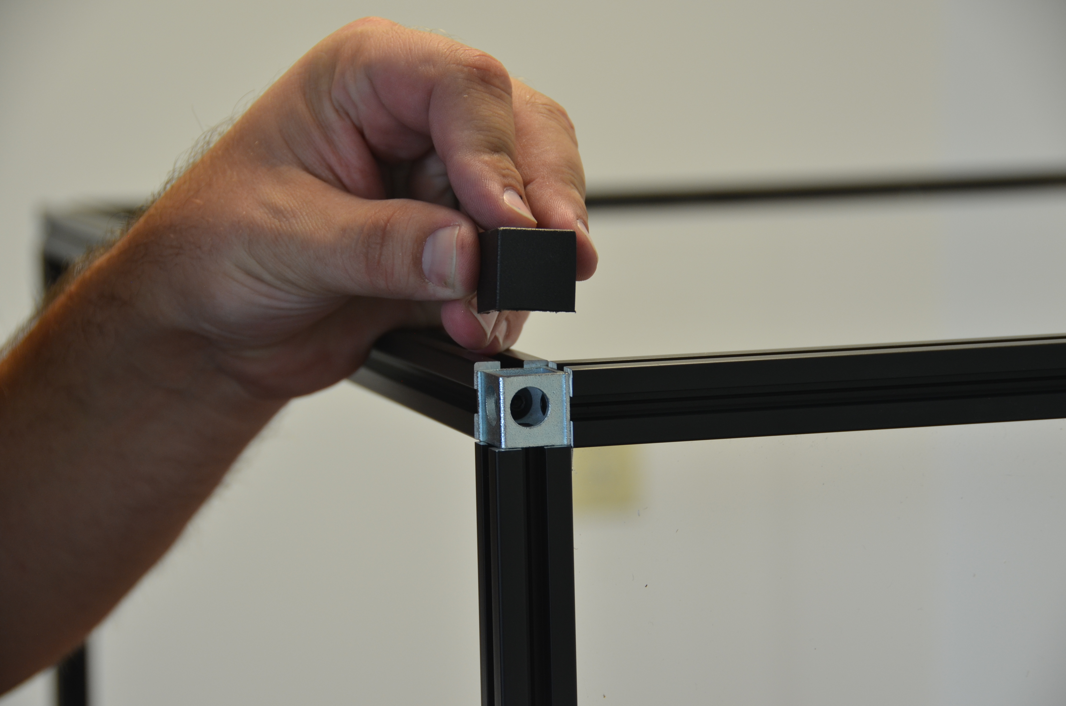
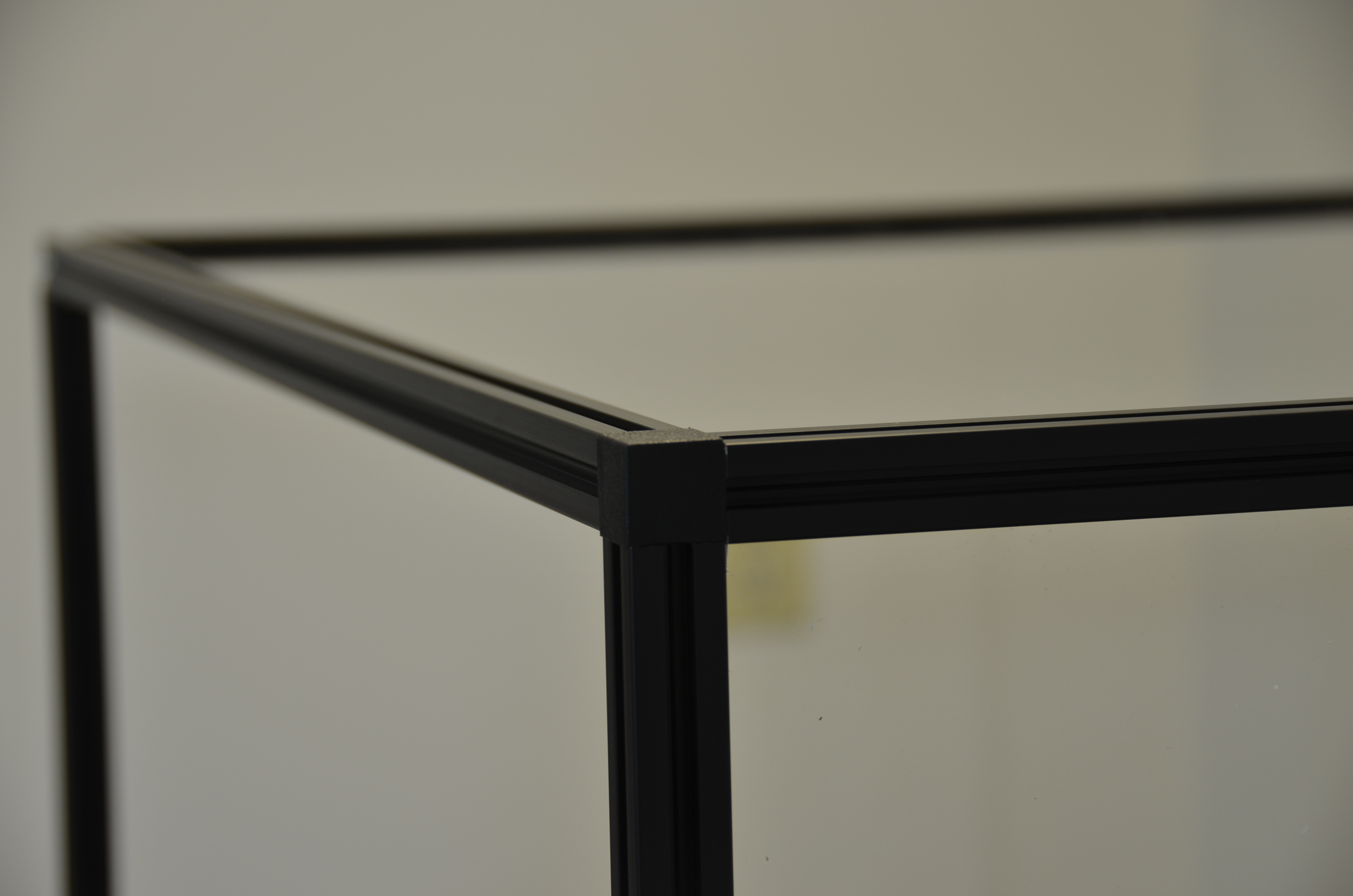
Use 4 Corner Connector Covers to cover each corner.
Flip the assembled base back over, onto your work surface.
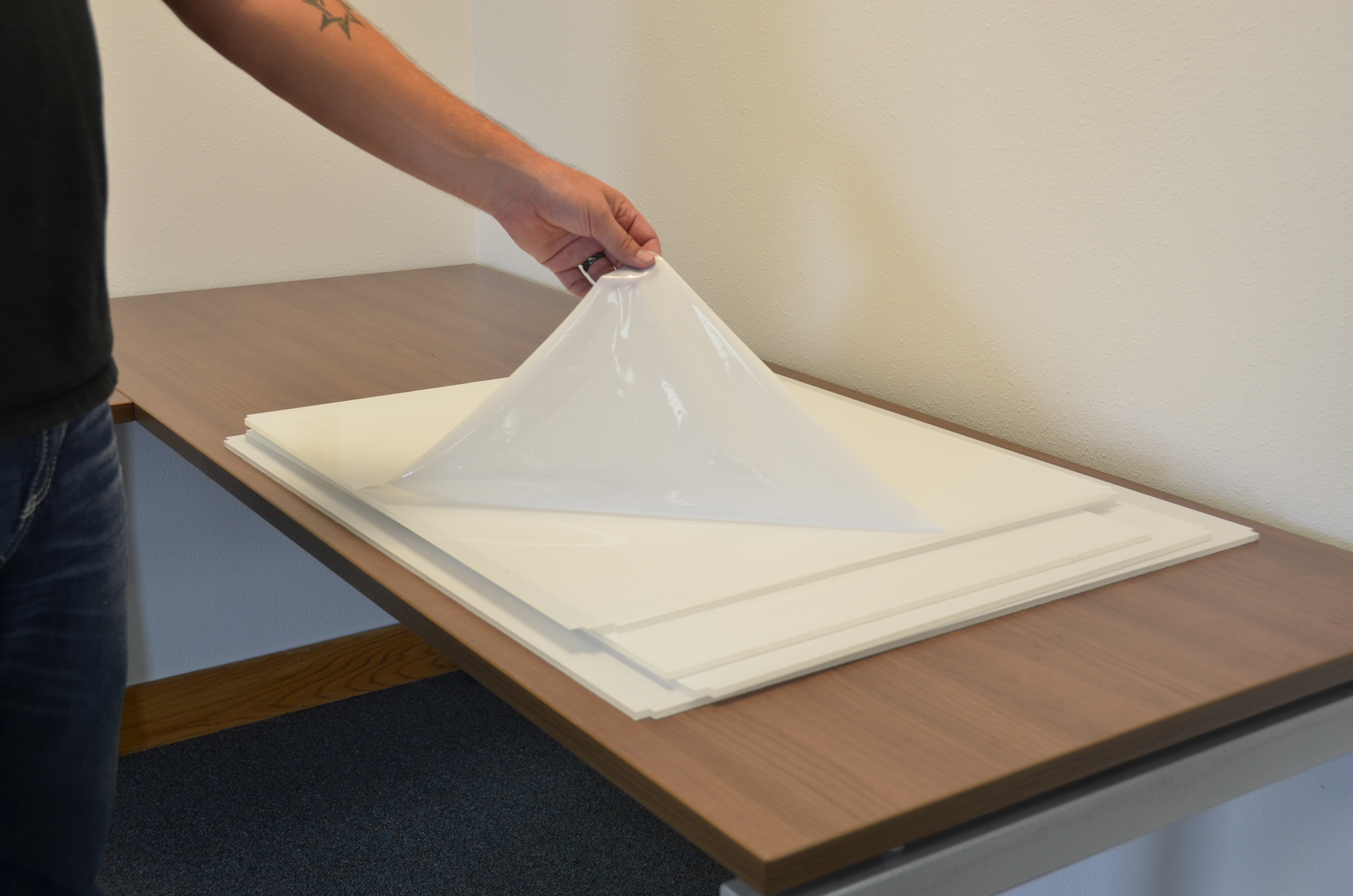
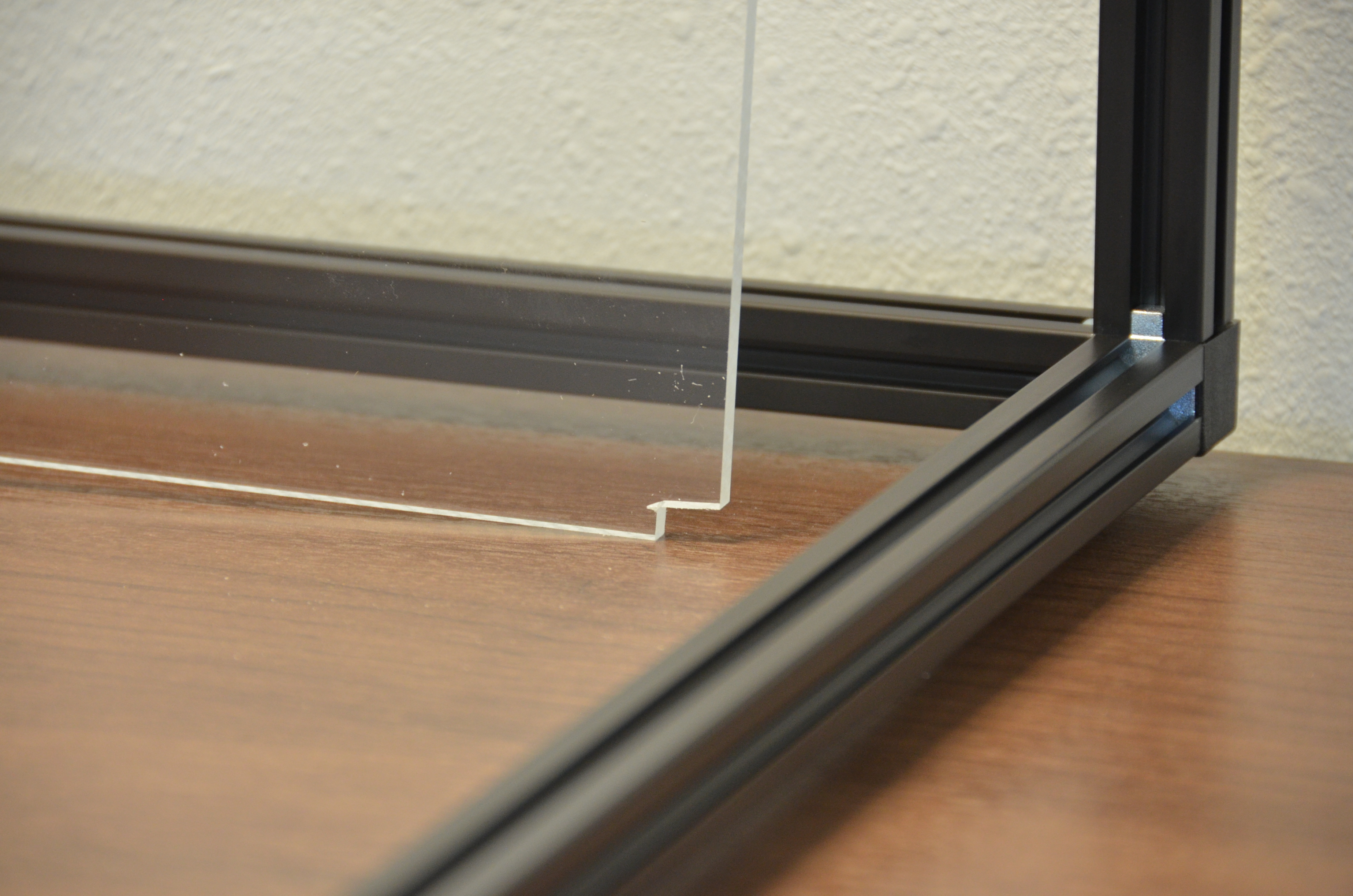
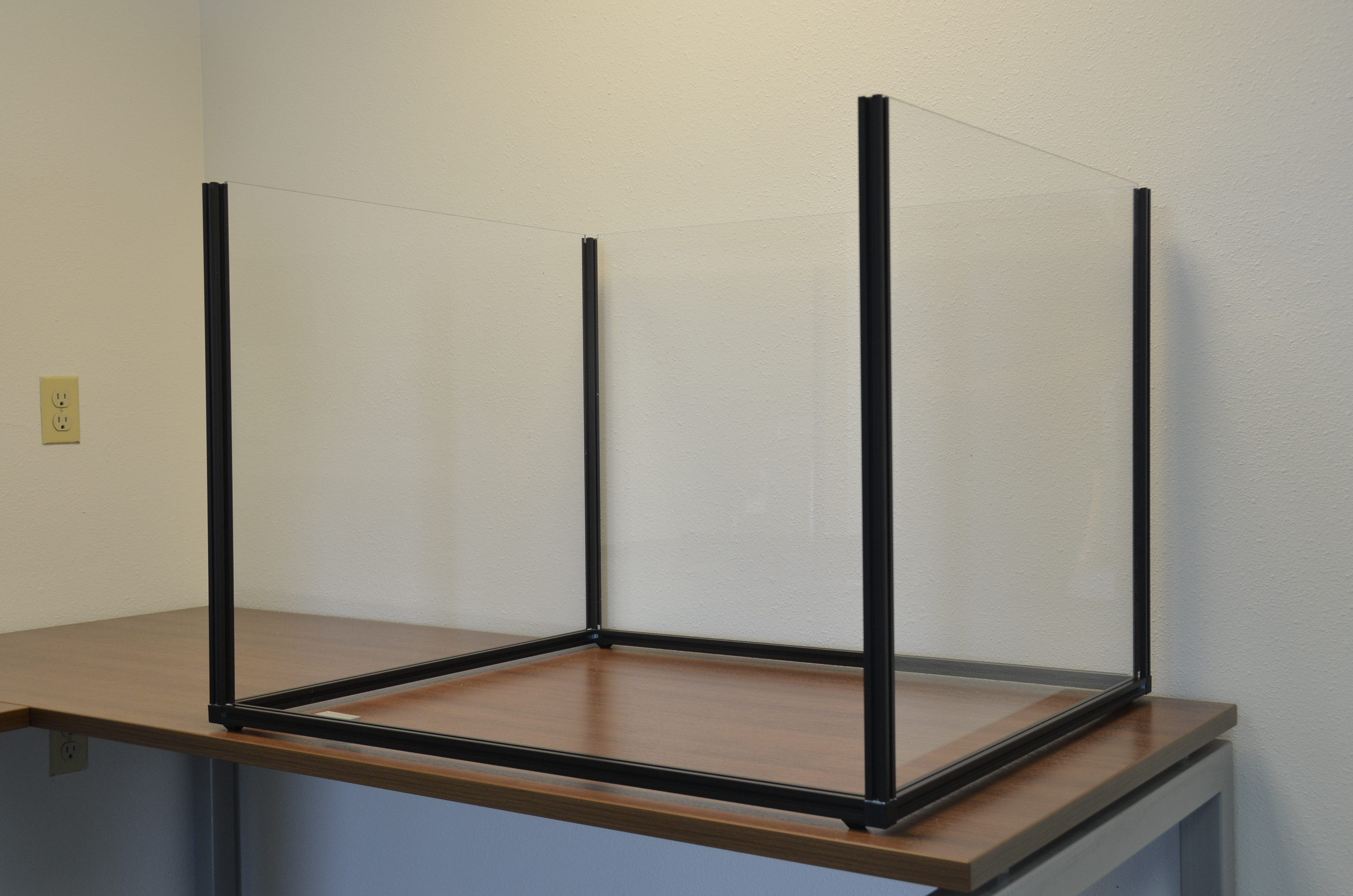
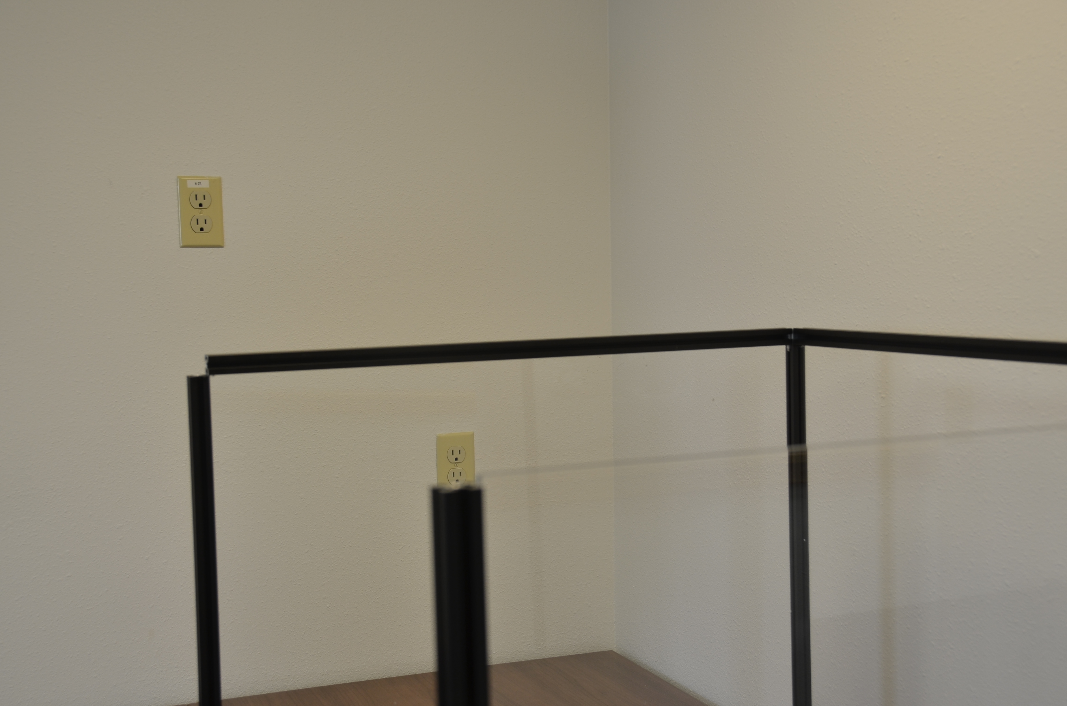
Install 3 clear panels into the CAT Guard. by sliding them into place. Make sure that they seat fully within each channel. Make sure that the cutout corners are on the bottom.
The clear panels are:
Slide in the clear back panel.
Slide in both clear side panels.
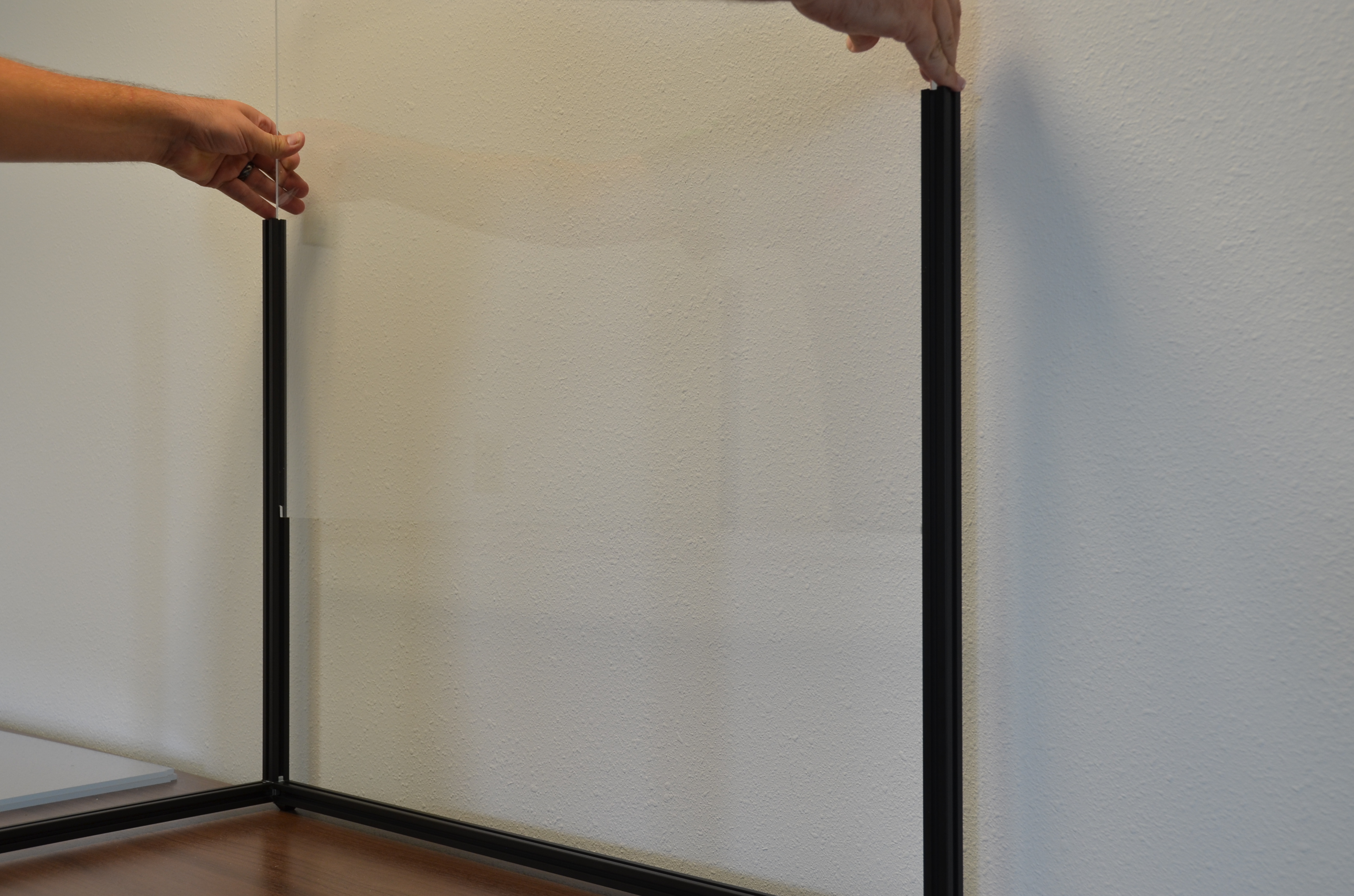

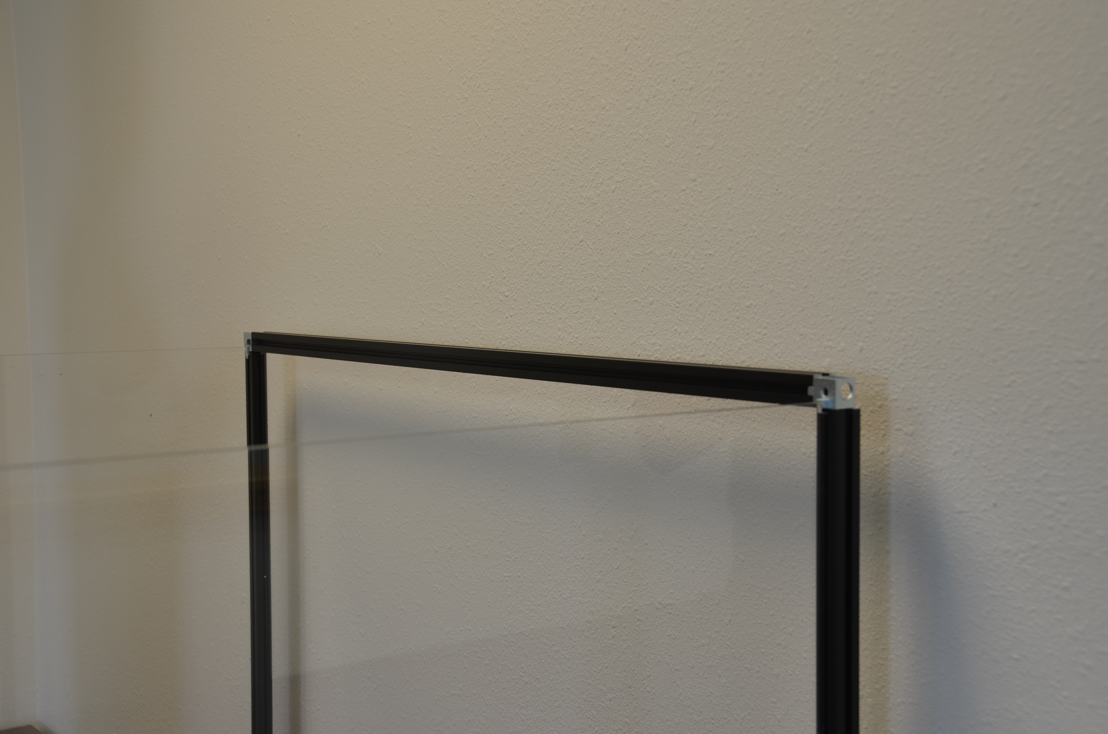


Place the 20mm x 20mm x 800mm extrusion on the front edge of the clear panel.
Use 2 corner connectors and 6 15mm M5 button cap screws to secure the front extrusion to the frame.
Cover the exposed corners with the Black Corner Covers.

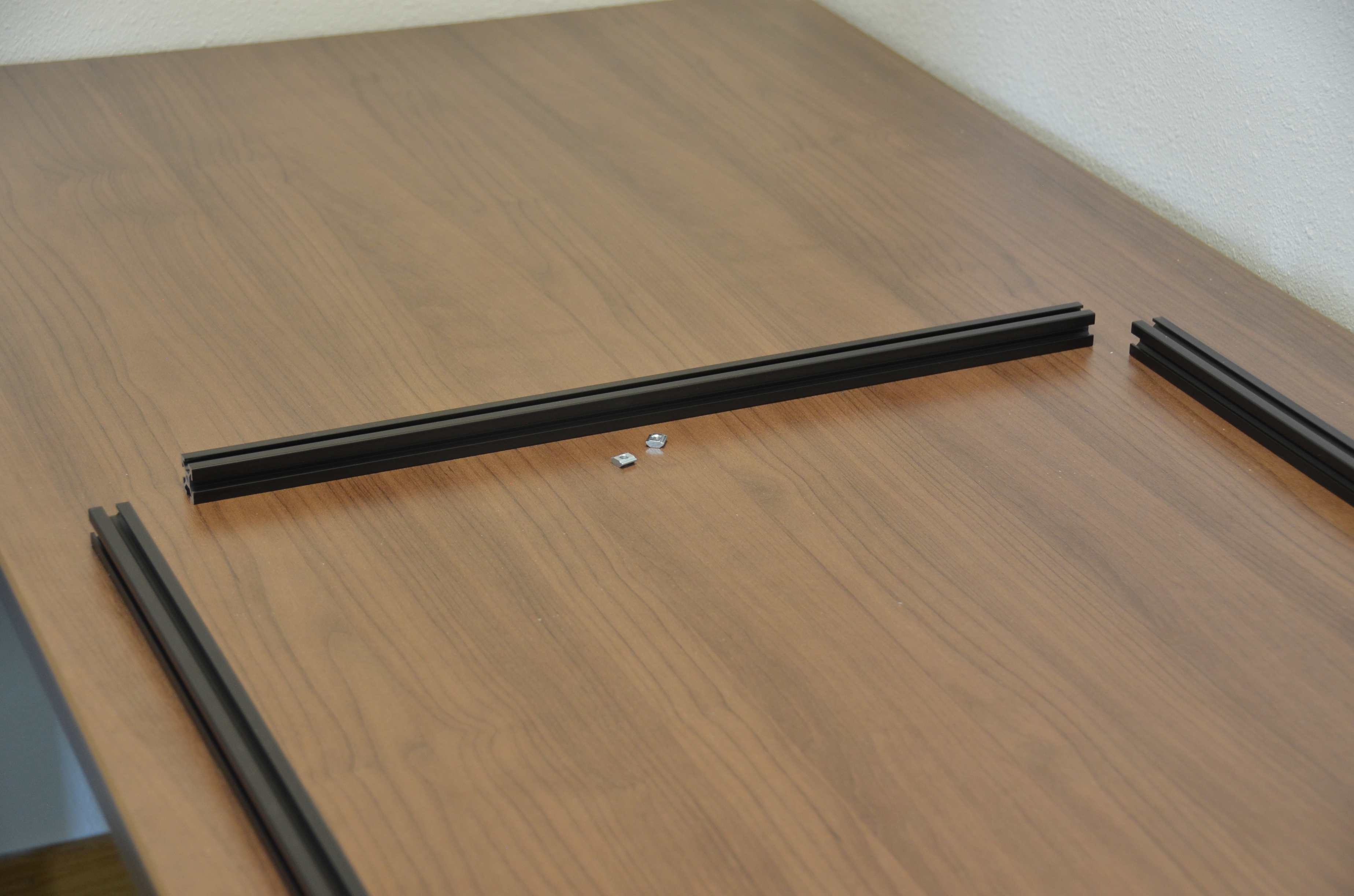
On a large clear surface lay out the following items:
Slide 2 M5 T-nuts into the bottom channel of the left hand extrusion.
Slide 4 M5 T-nuts into the bottom channel of the right hand extrusion.
Slide 1 M3T-nuts into the top channel of the extrusion closest to you.
Slide 2 M5 T-nuts into the top of each end of the aluminum extrusion.
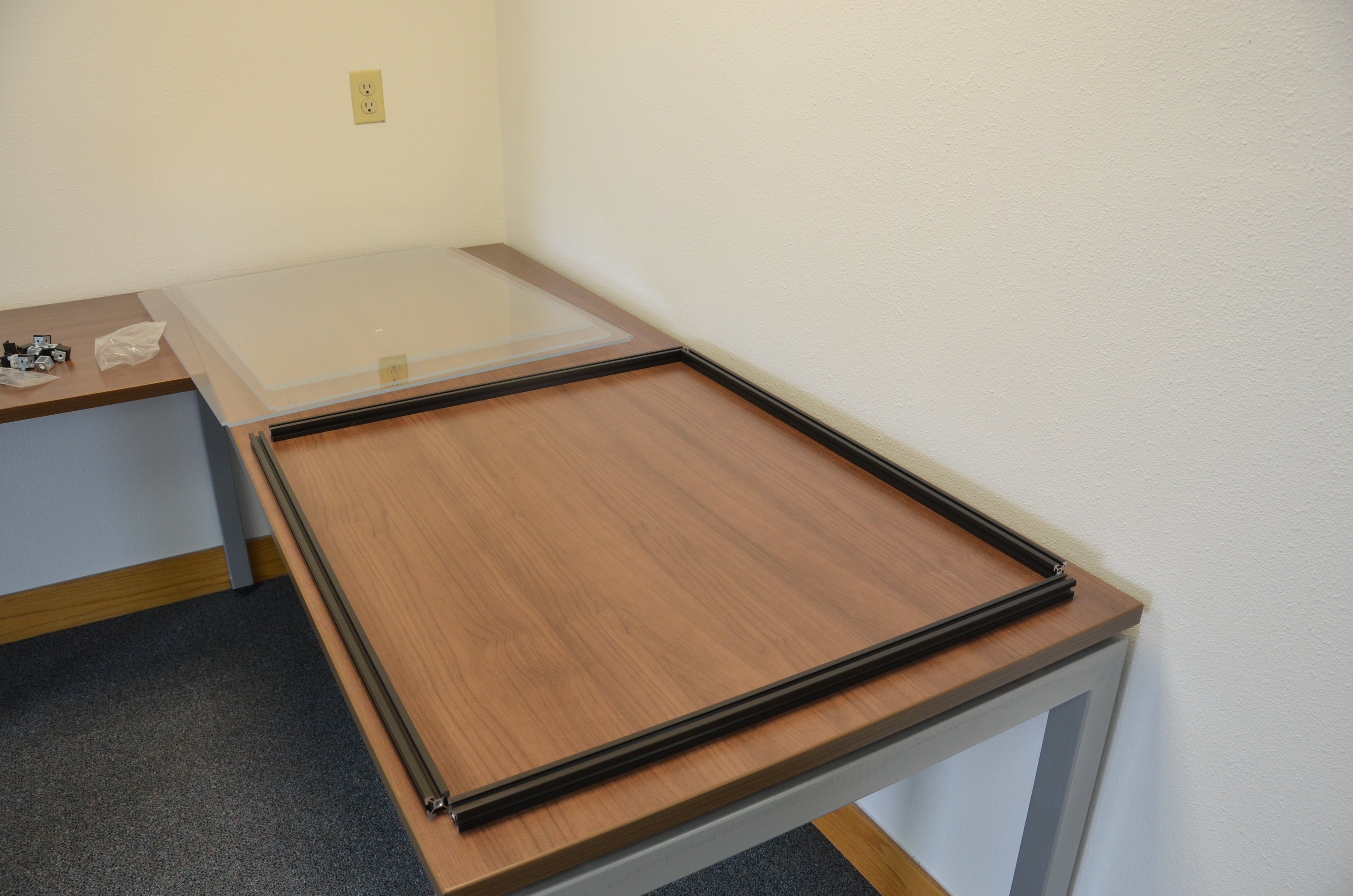
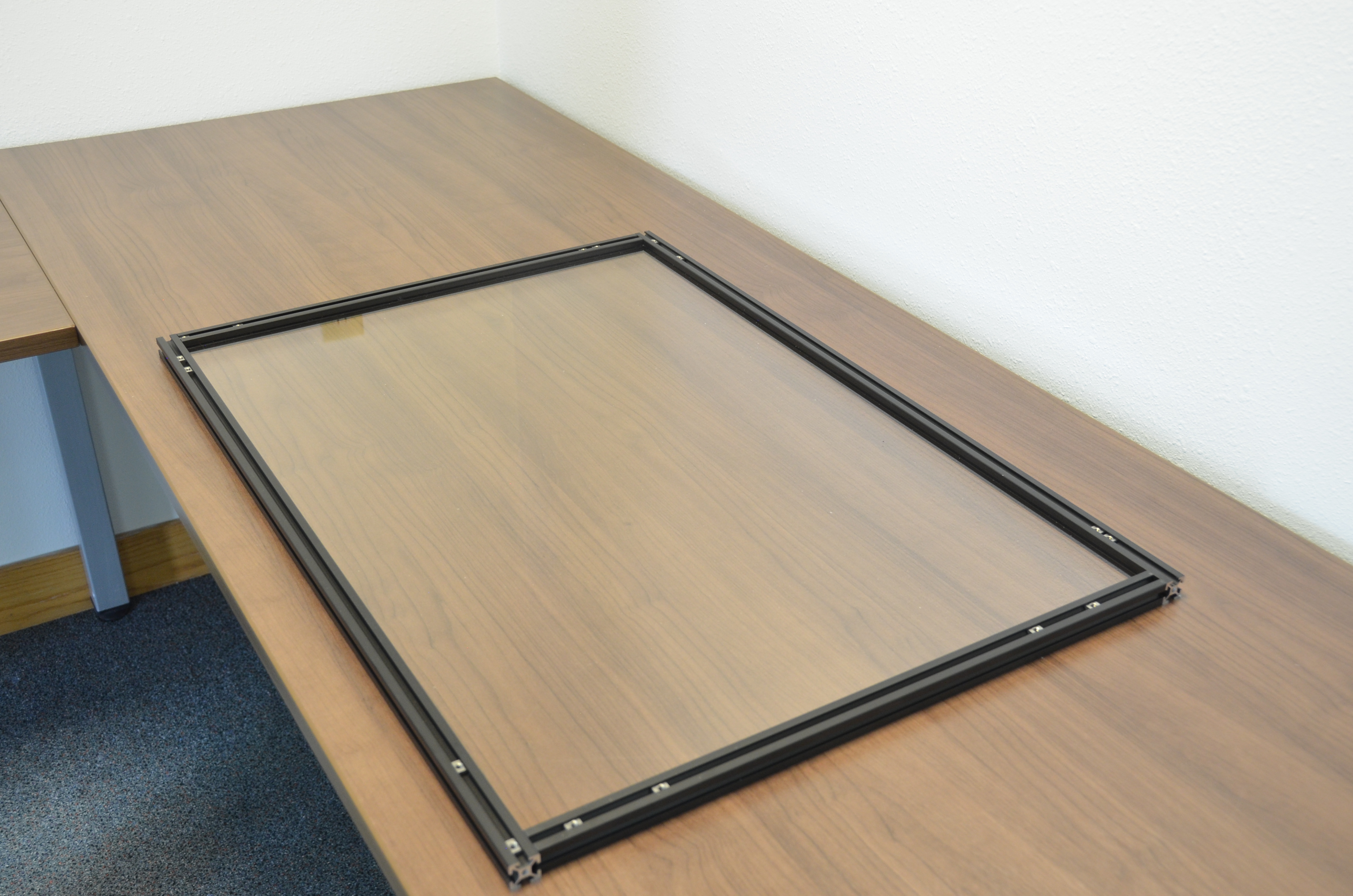
Carefully place the clear plastic panel into the middle of the laid out extrusions.
Slide each extrusion onto the corresponding edge of the clear panel.
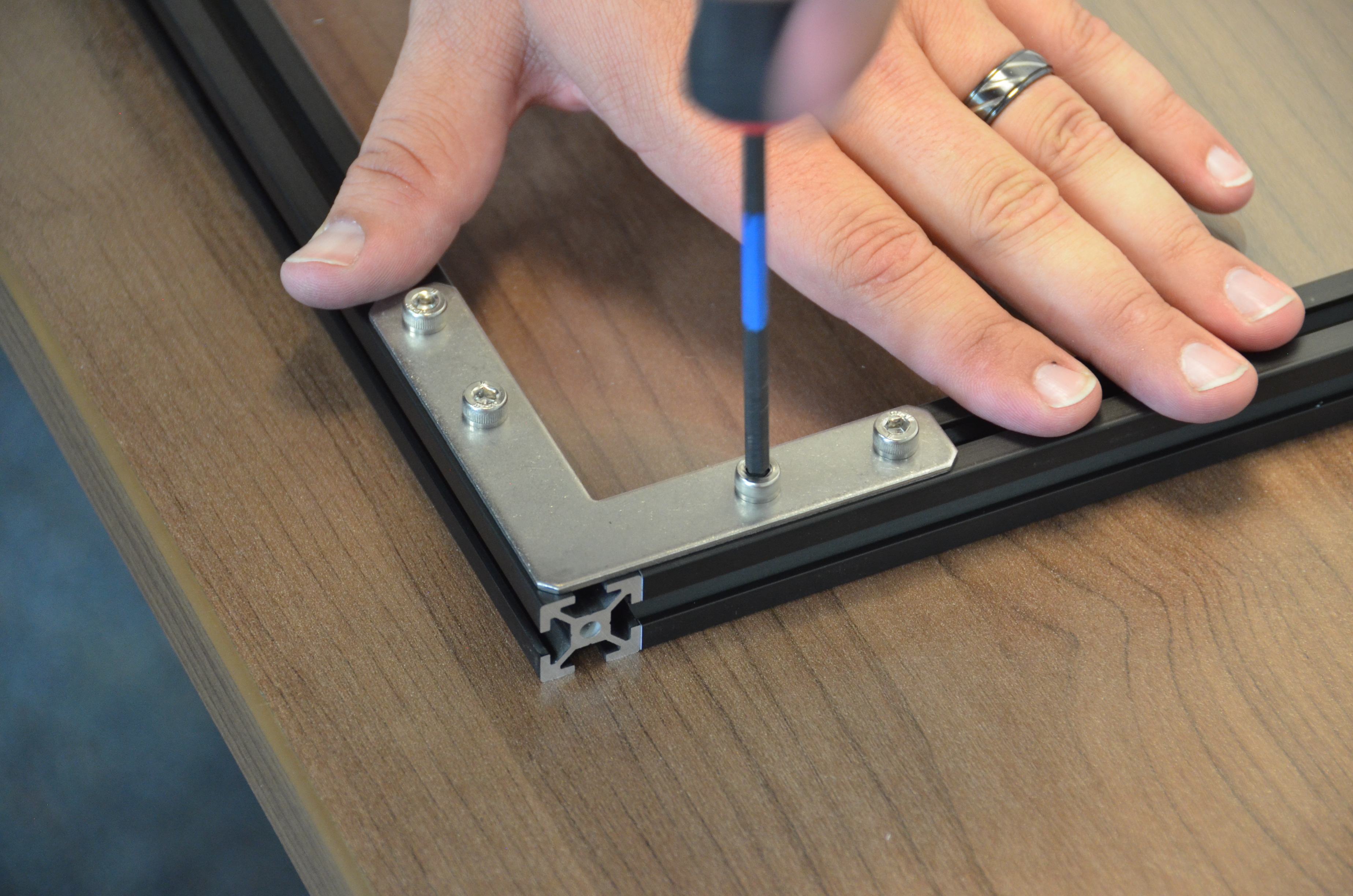
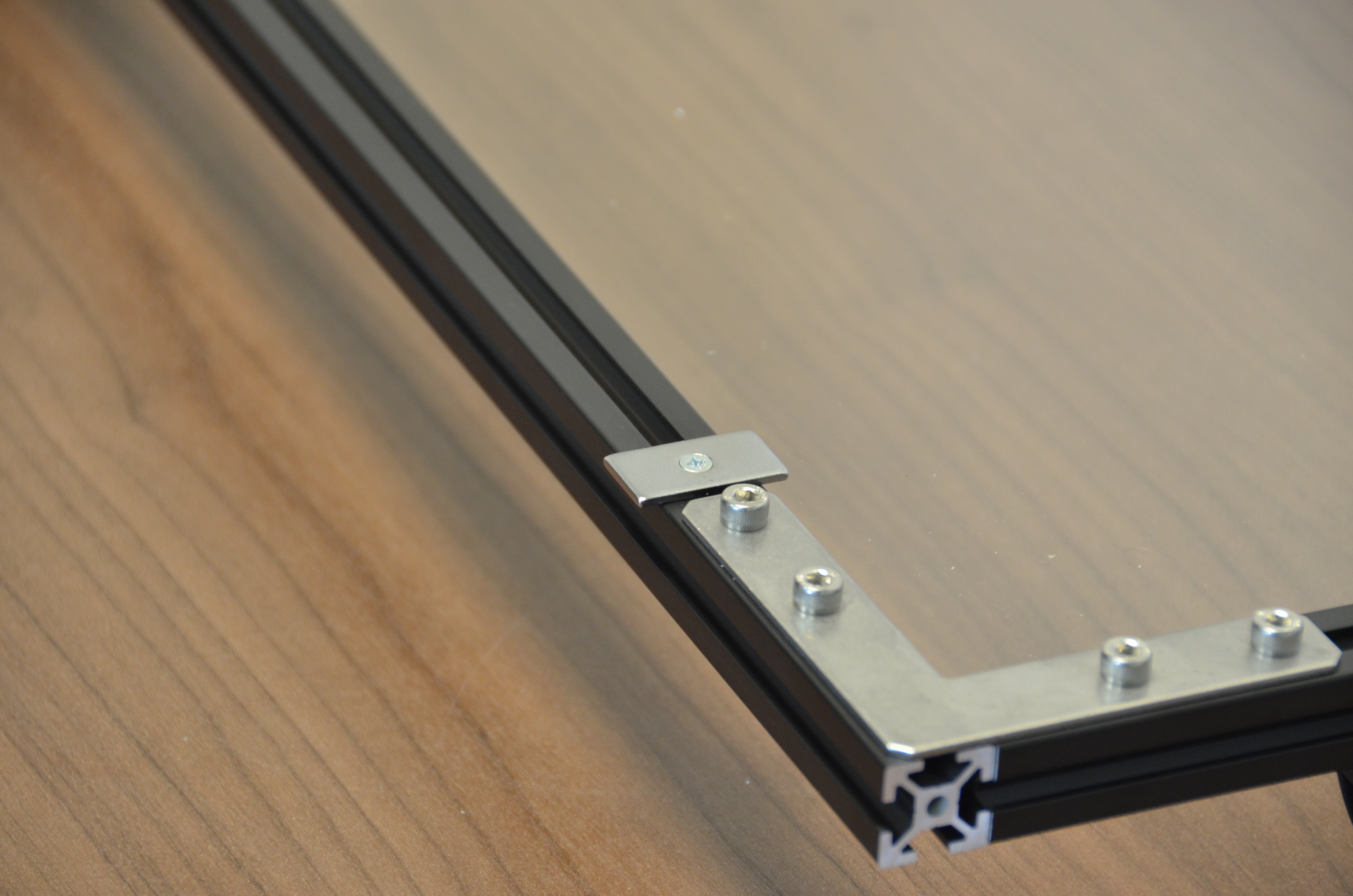
Place the L bracket on one corner of the door frame and use 4 8mm M5 Socket Head cap screws to secure the corner bracket onto the door frame.
Repeat for the three other corners.
On the Front Right Hand corner insert 2 M5 T-nuts__ into the top of the front extrusion. This will serve as a moutning point for the magnetic latch in the next step.


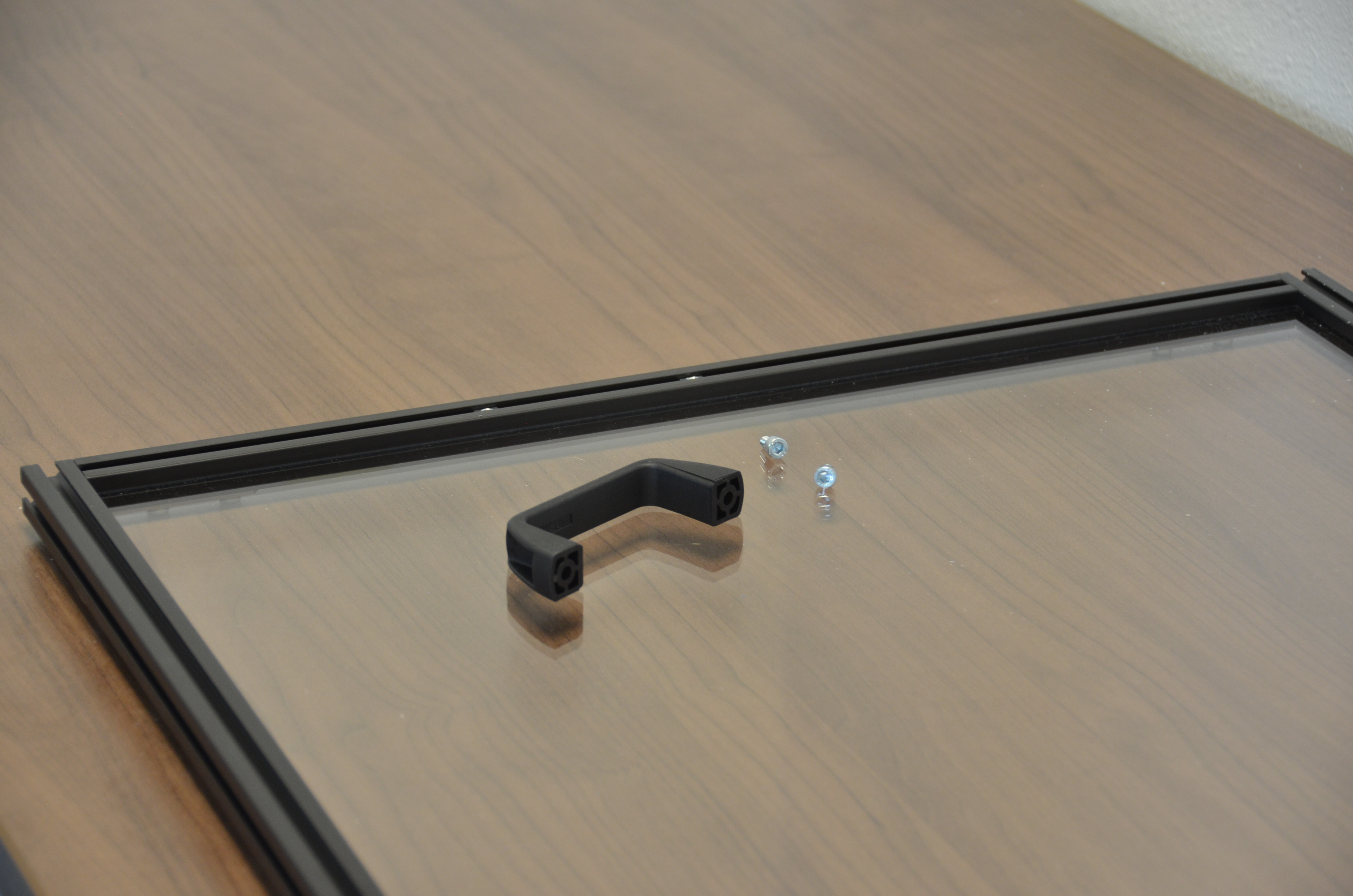
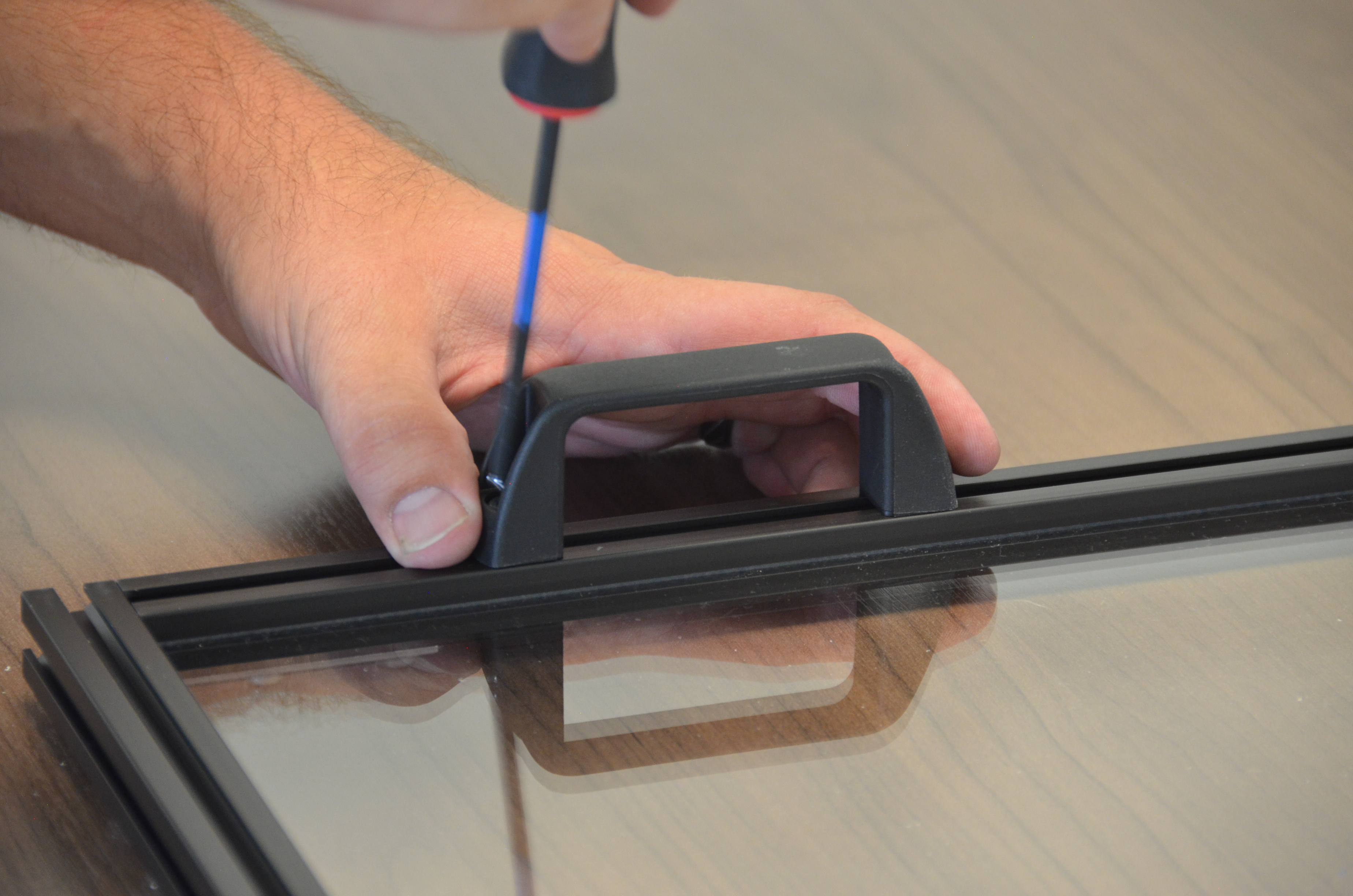
Install the Black Plastic Handle
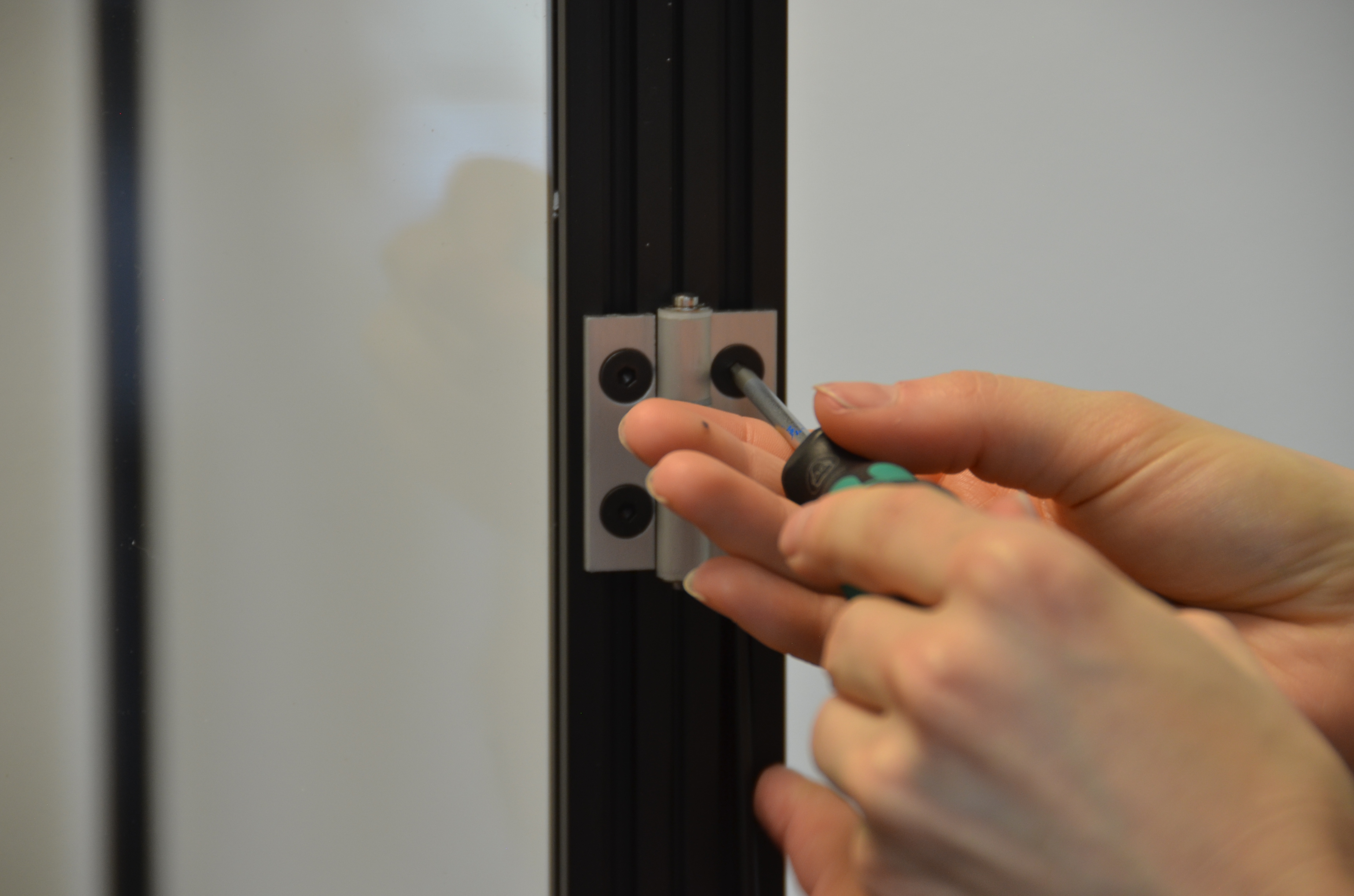
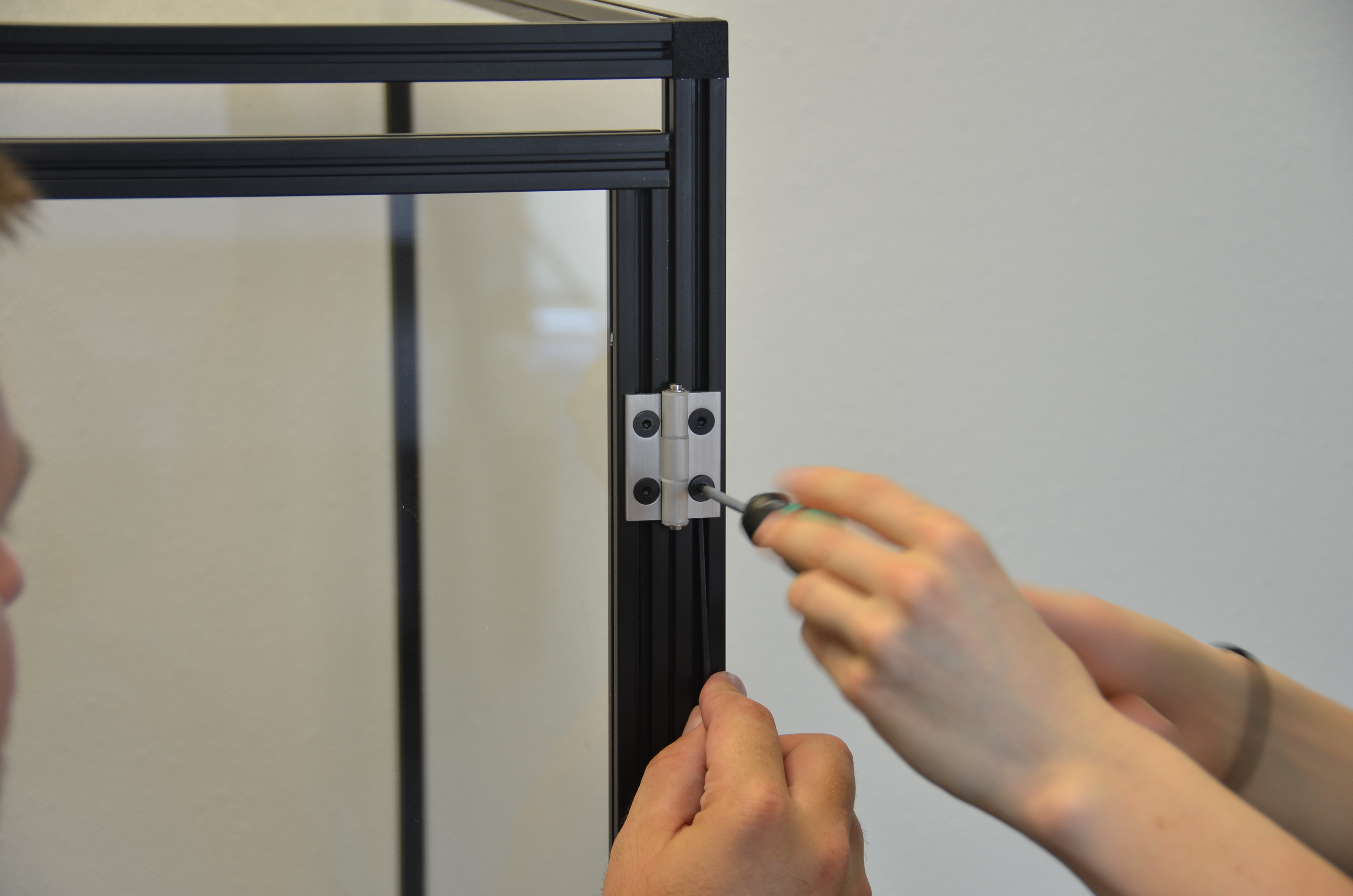
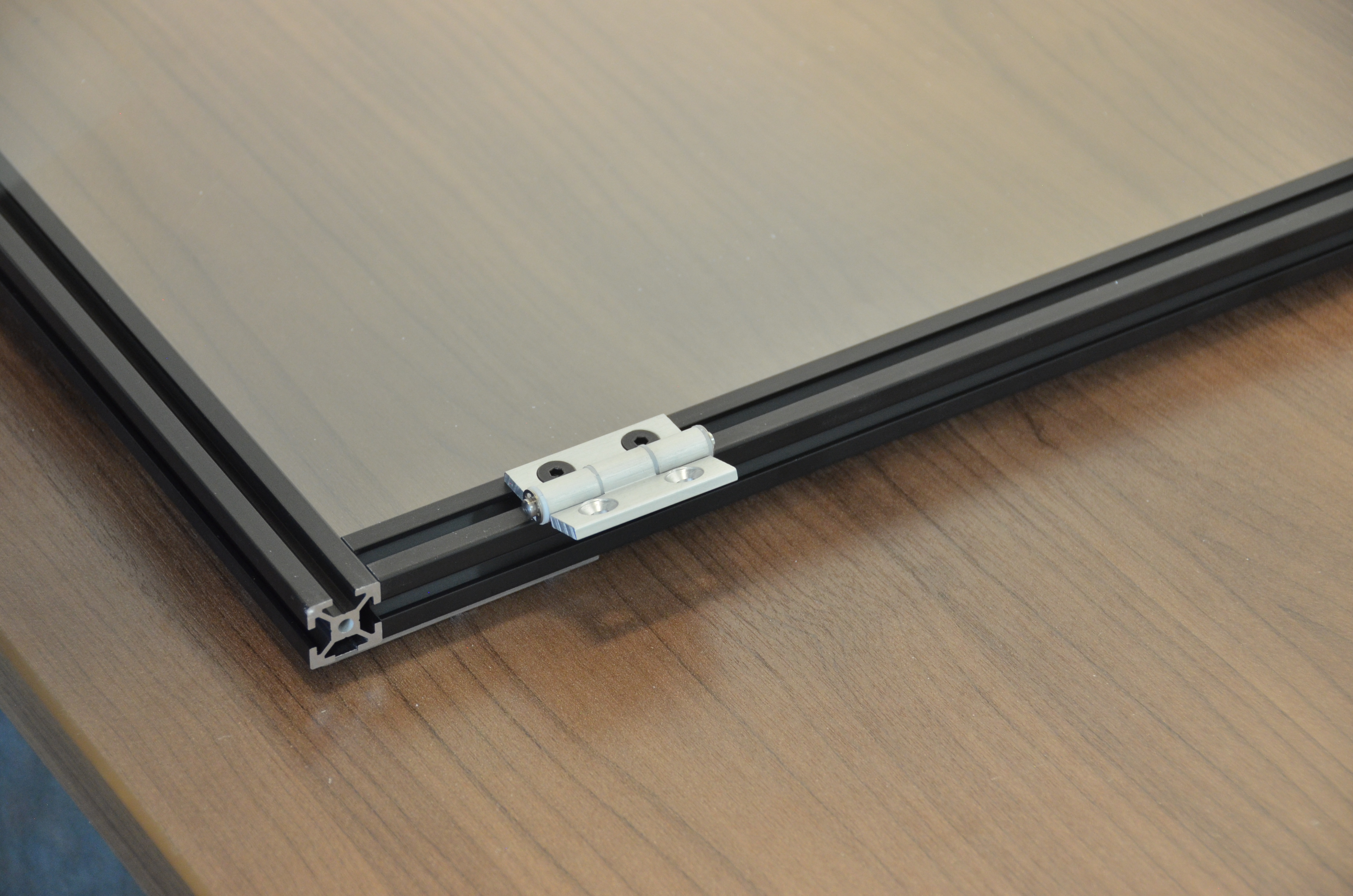
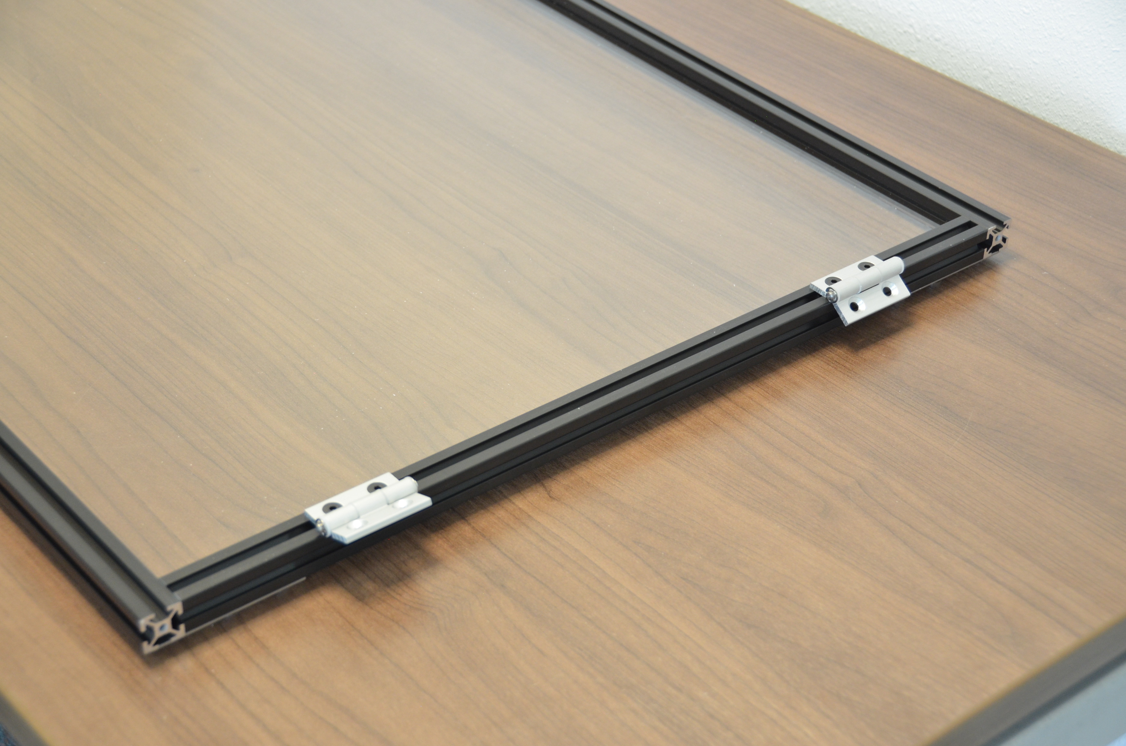
Install the two hinges:
Flip the door assembly over.
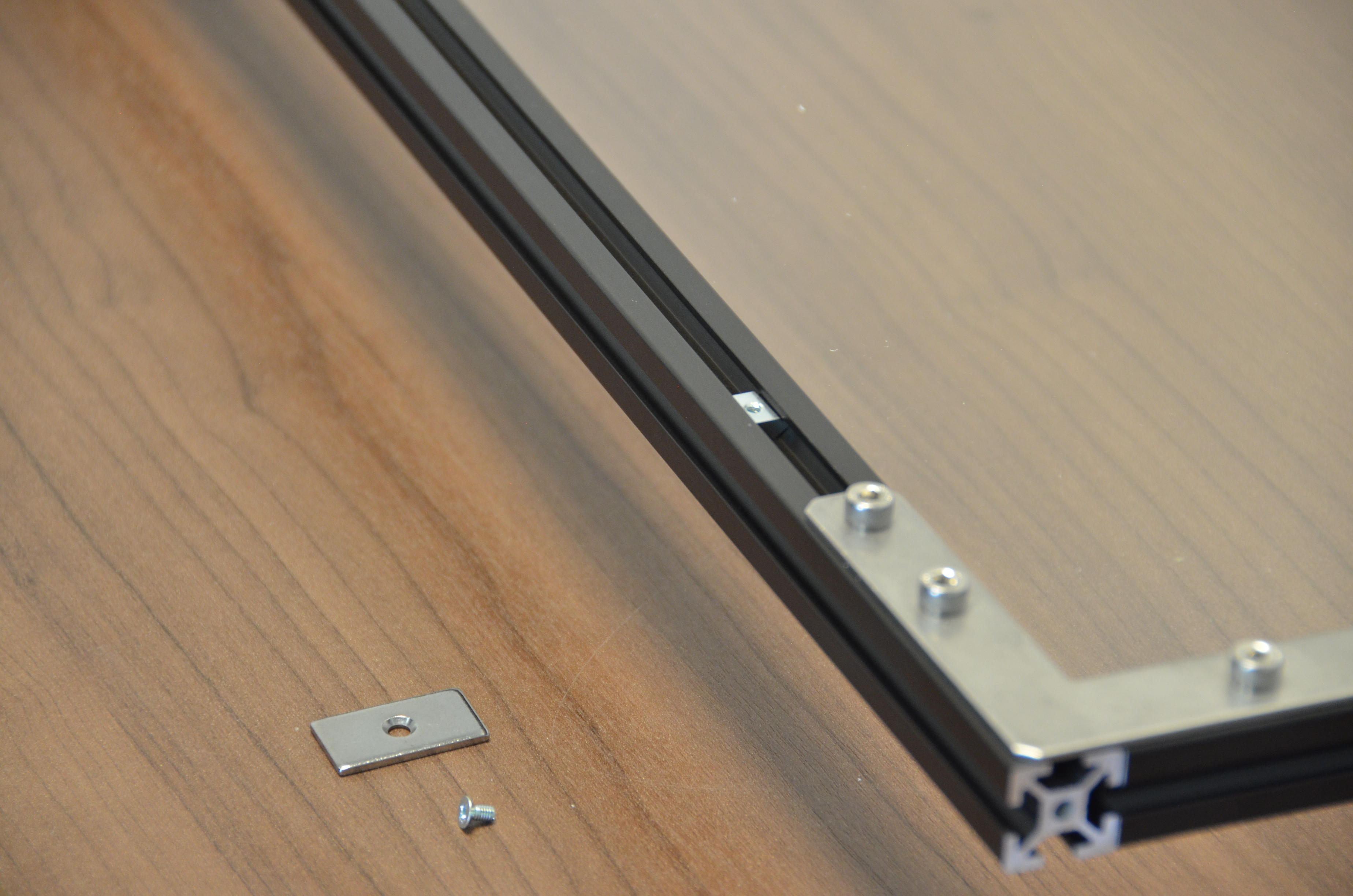
Use the 4mm M3 Flat Head cap screw to secure the metal plate to the right hand corner of the door frame. Rotate and mount the plate as shown
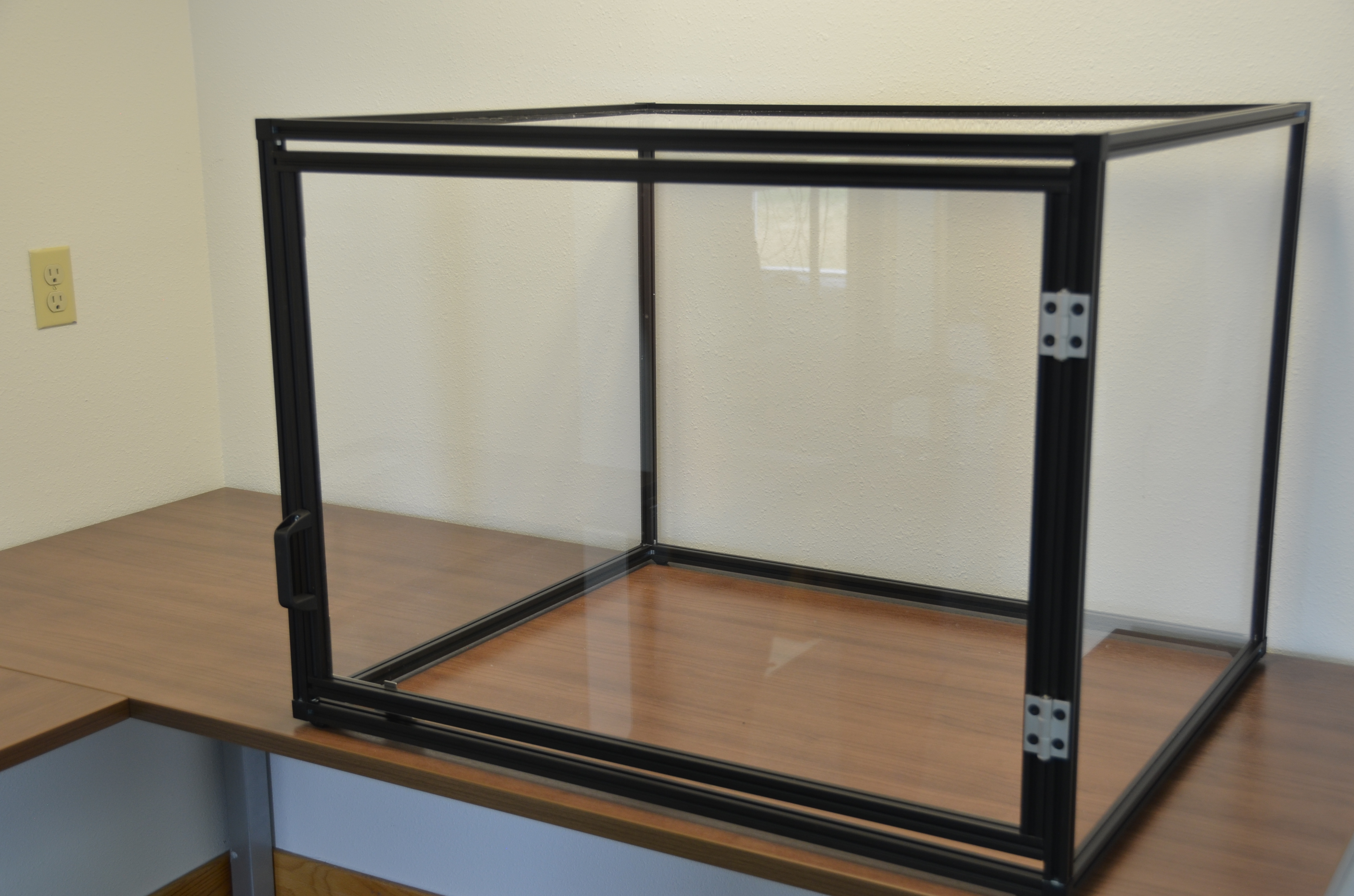
Place the door into the CAT-Guard frame opening.
Slide the 2 T-nuts up to align them under the hinges.
Use 2 8mm M5 Socket Head cap screws to secure each hinge onto the frame.
Center the door within the opening before tightening down the hinges.
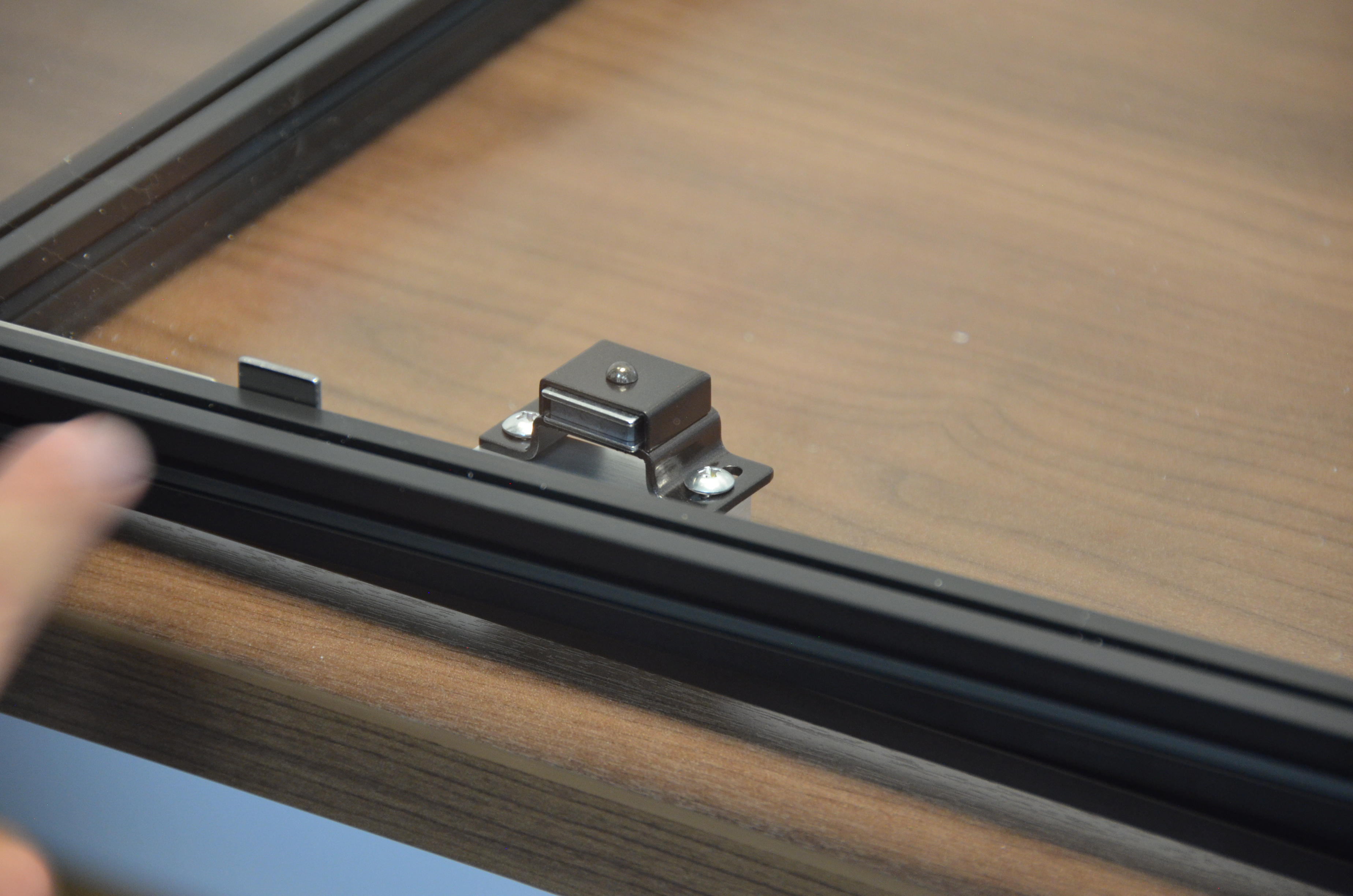
Mount the Magnetic Latch
Verify door operation.