Open HardwareAssembly Instructions
Guides for installation and assembly of the LulzBot line of products made by FAME 3D LLC.
Guides for installation and assembly of the LulzBot line of products made by FAME 3D LLC.
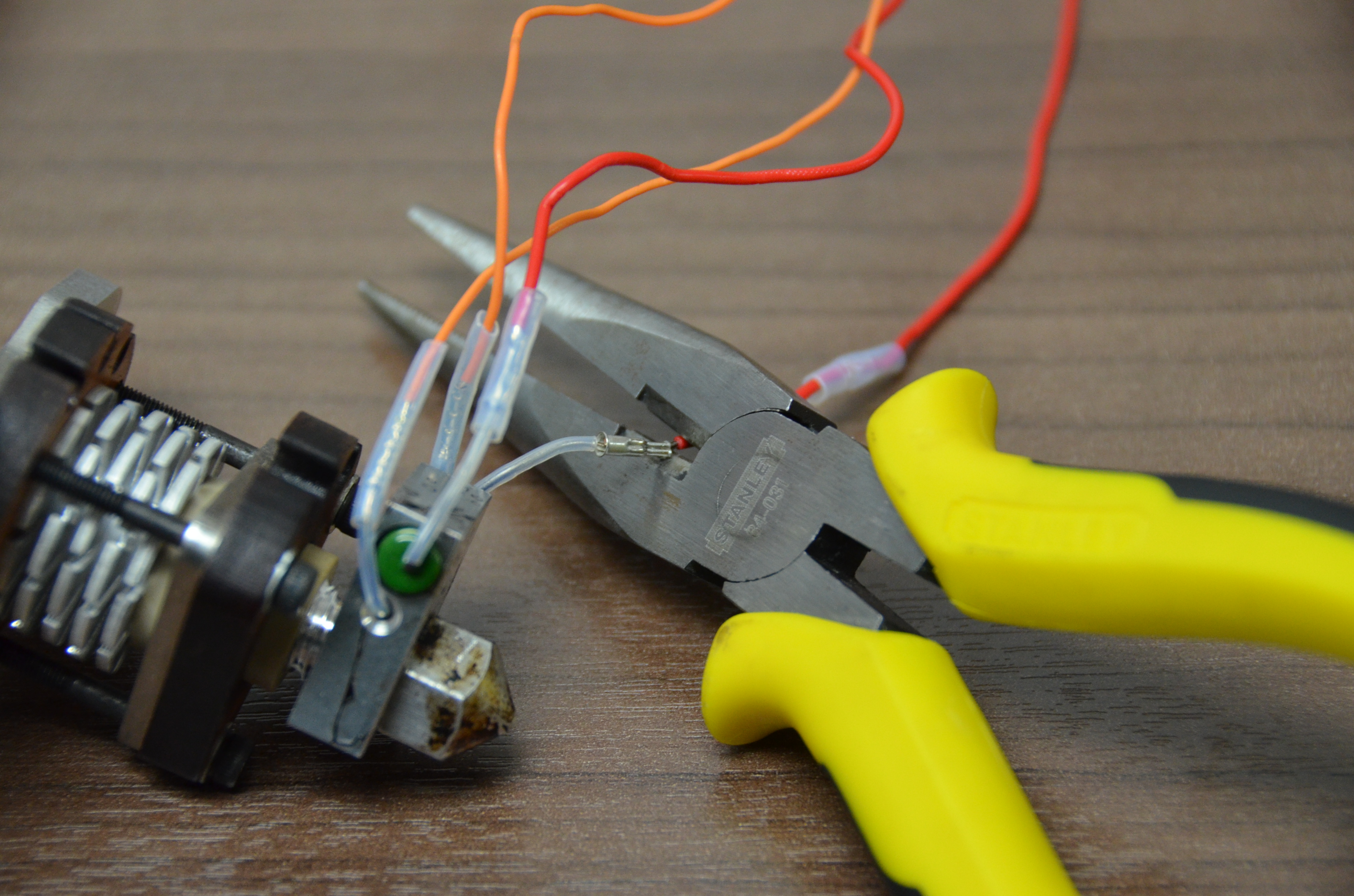
Tools Required
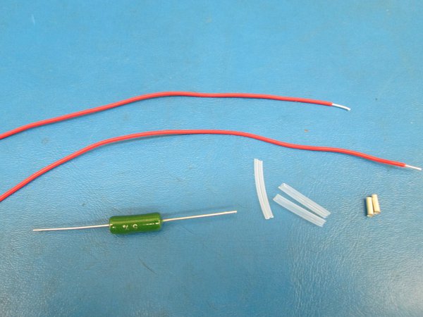
Parts Required
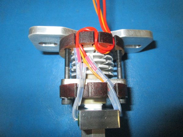
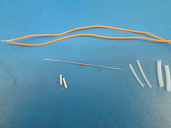
Wire Insulation:
2x PTFE Insulation 11 AWGMcMaster-Carr 5239K11, 18mm length- saved from existing Budaschnozzle
Or Polyamide/Kapton Tape, only if existing PTFE sleeving is damaged or lost
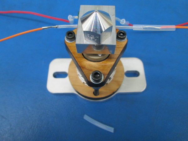
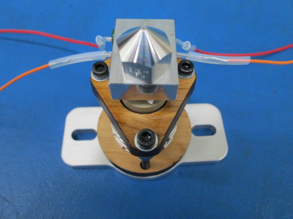
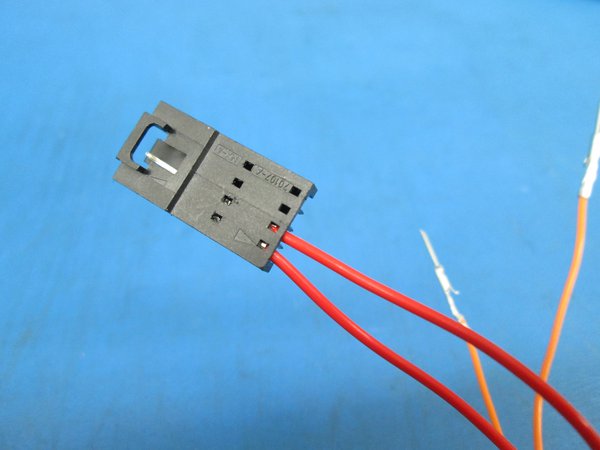
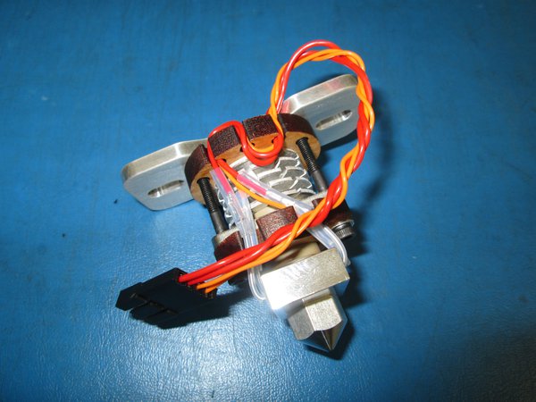
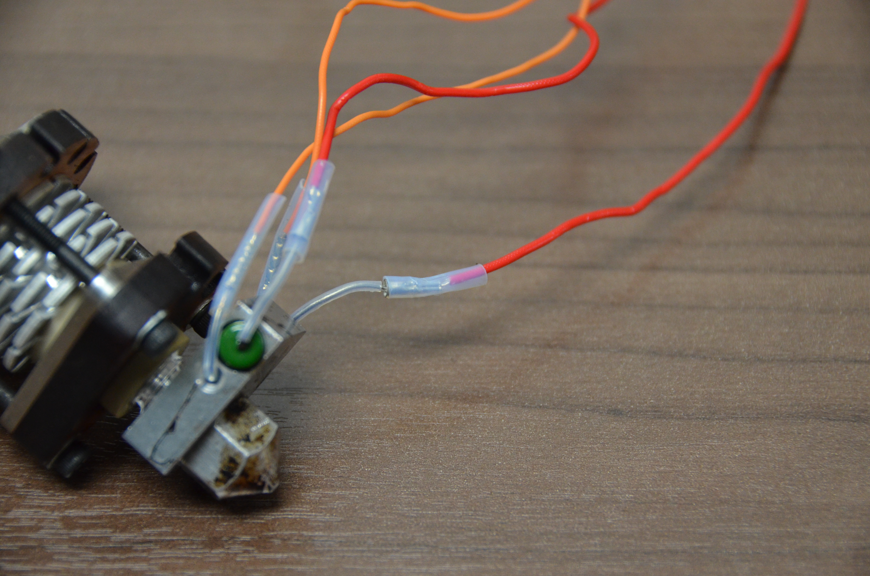
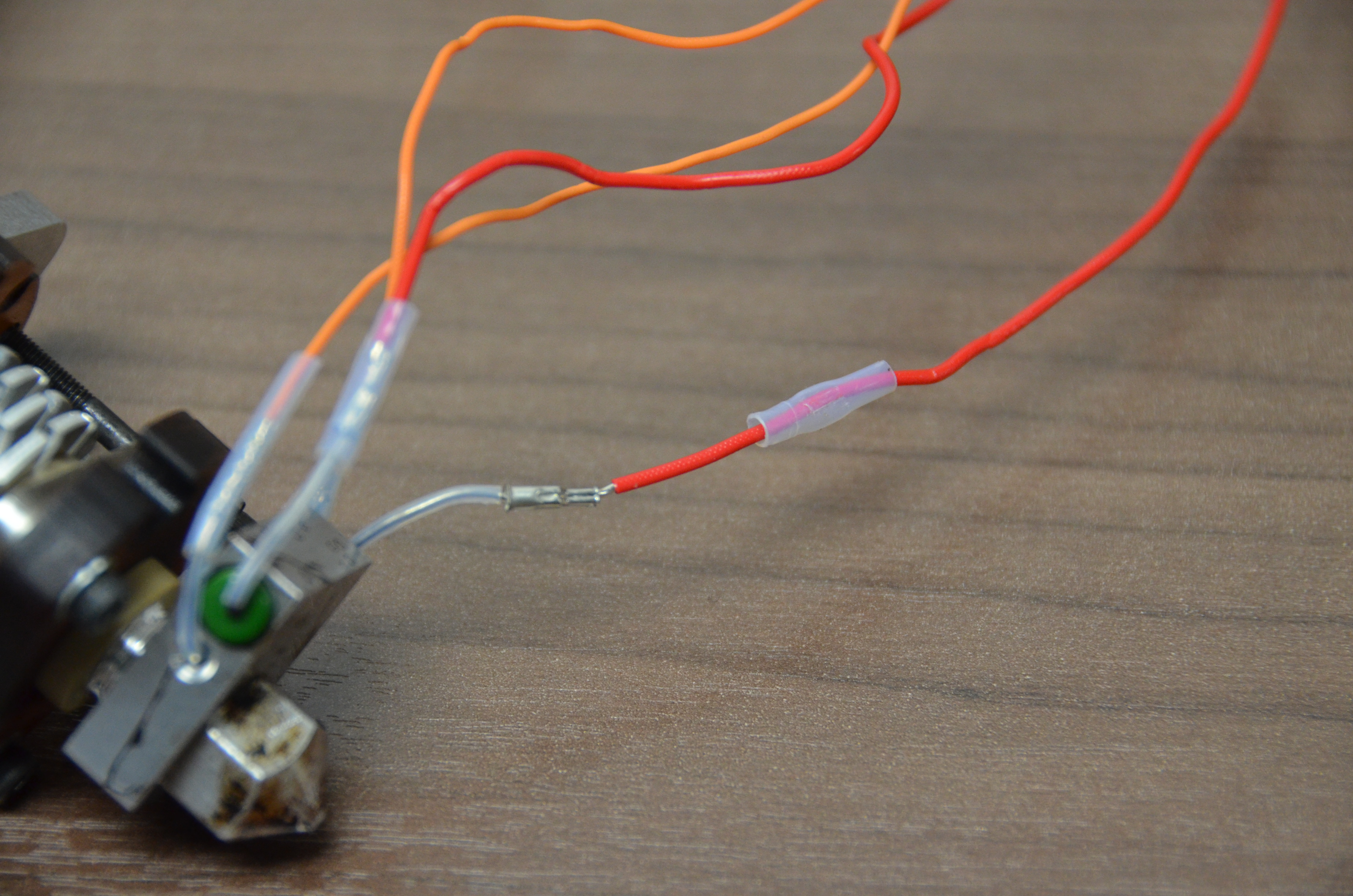
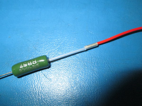
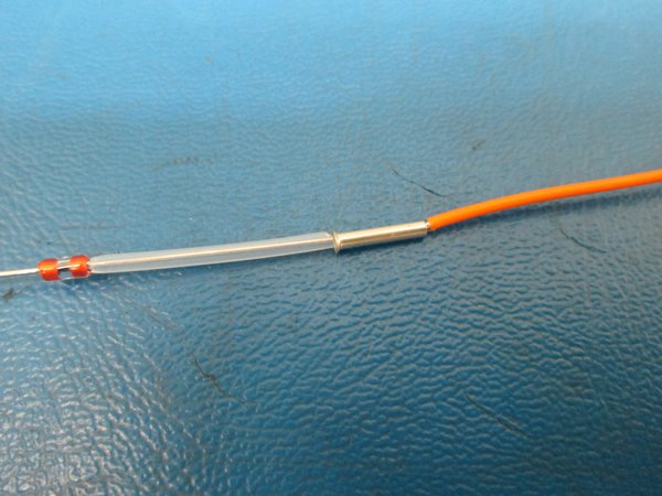
The RED wire pairs lead to the Heater Resistor and the ORANGE wire pairs go to the Thermistor.
Do not attempt to solder the connections for the hot end can reach temperatures high enough to fail- usually during a print.

Procedure:
Procedure:

Thermistor:
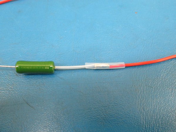
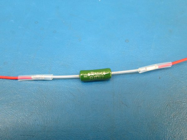
Heater Resistor:
Route the wires: