Open HardwareAssembly Instructions
Guides for installation and assembly of the LulzBot line of products made by FAME 3D LLC.
Guides for installation and assembly of the LulzBot line of products made by FAME 3D LLC.
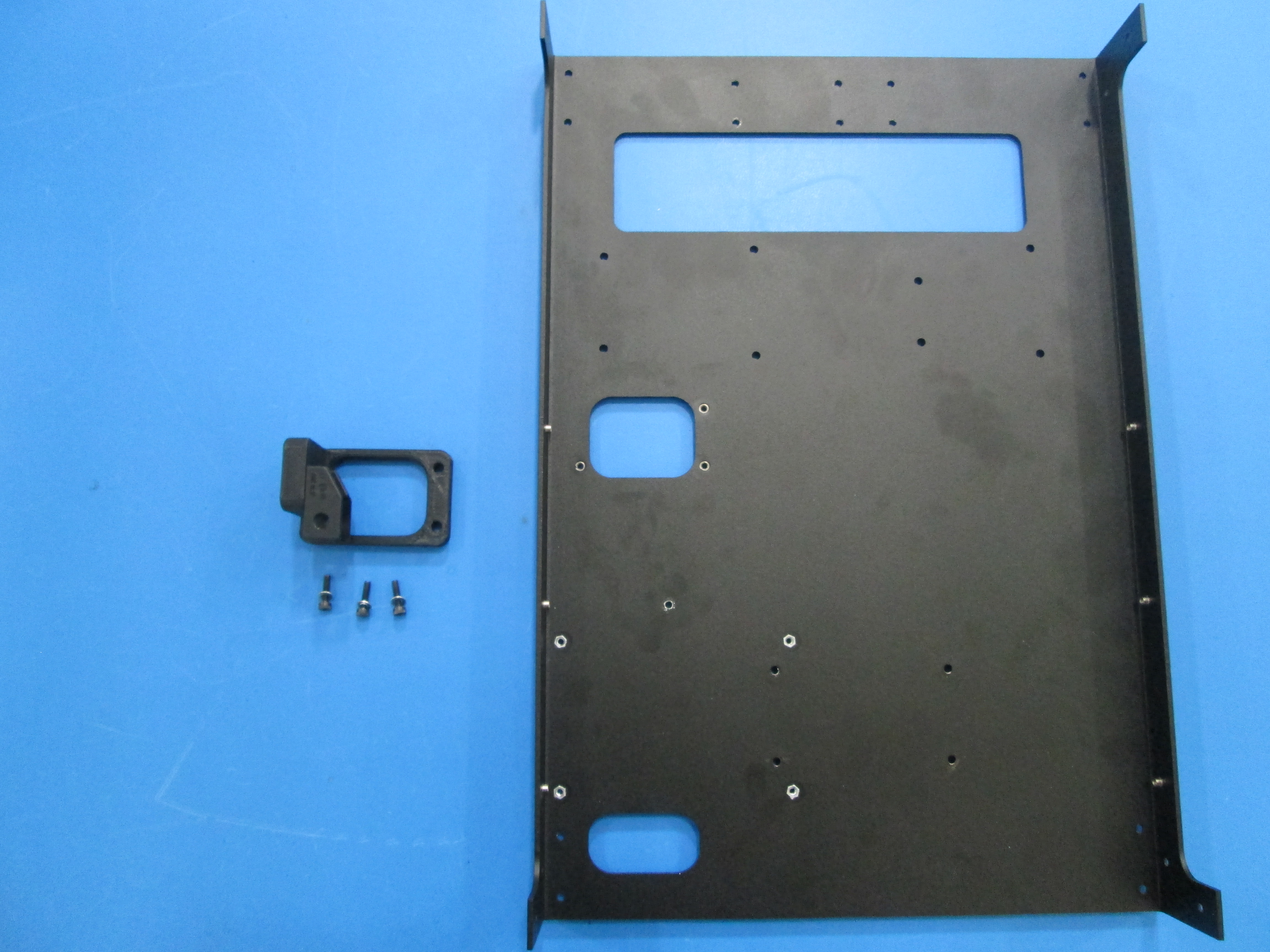
Components Required
Tools Required

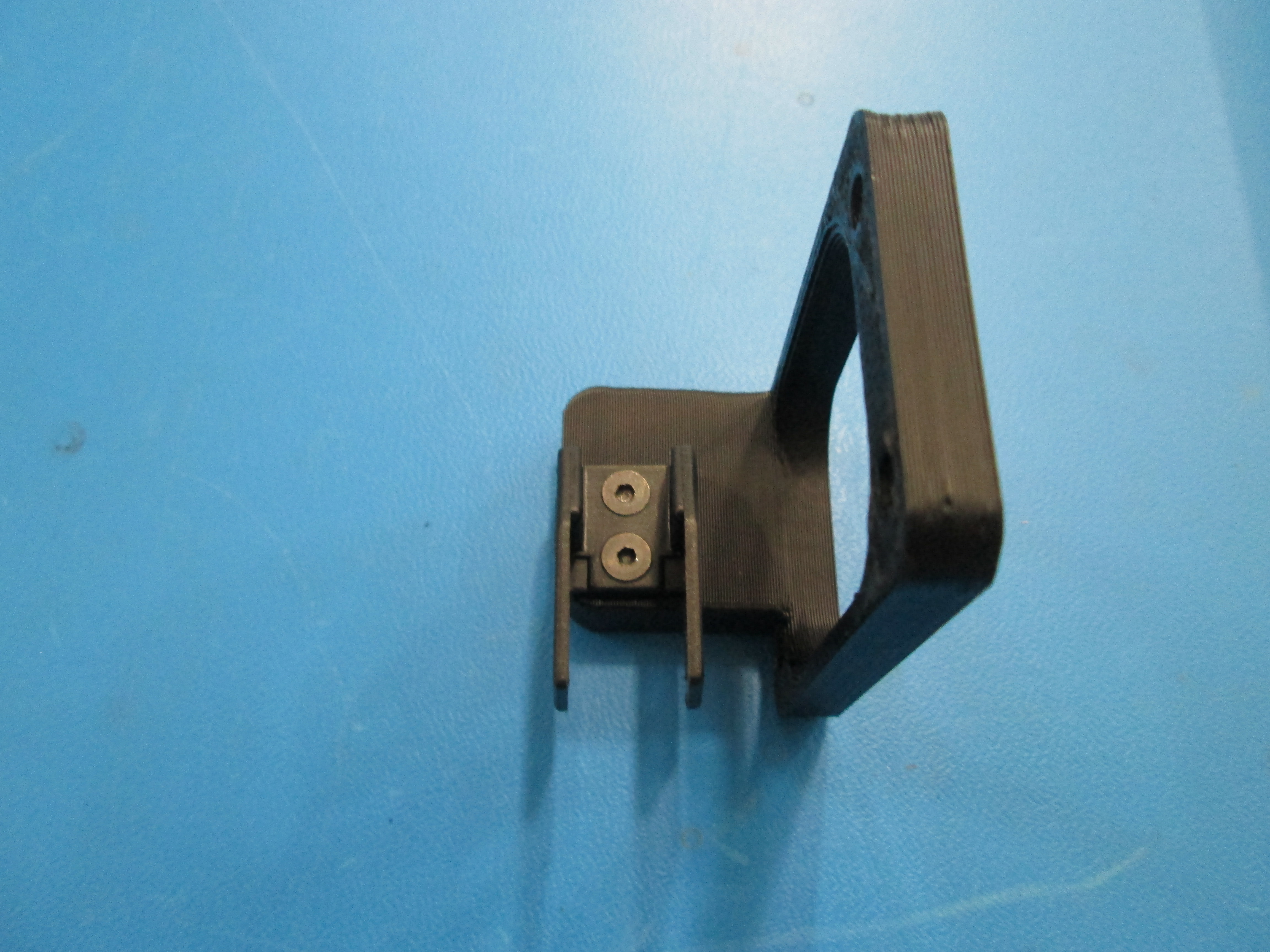
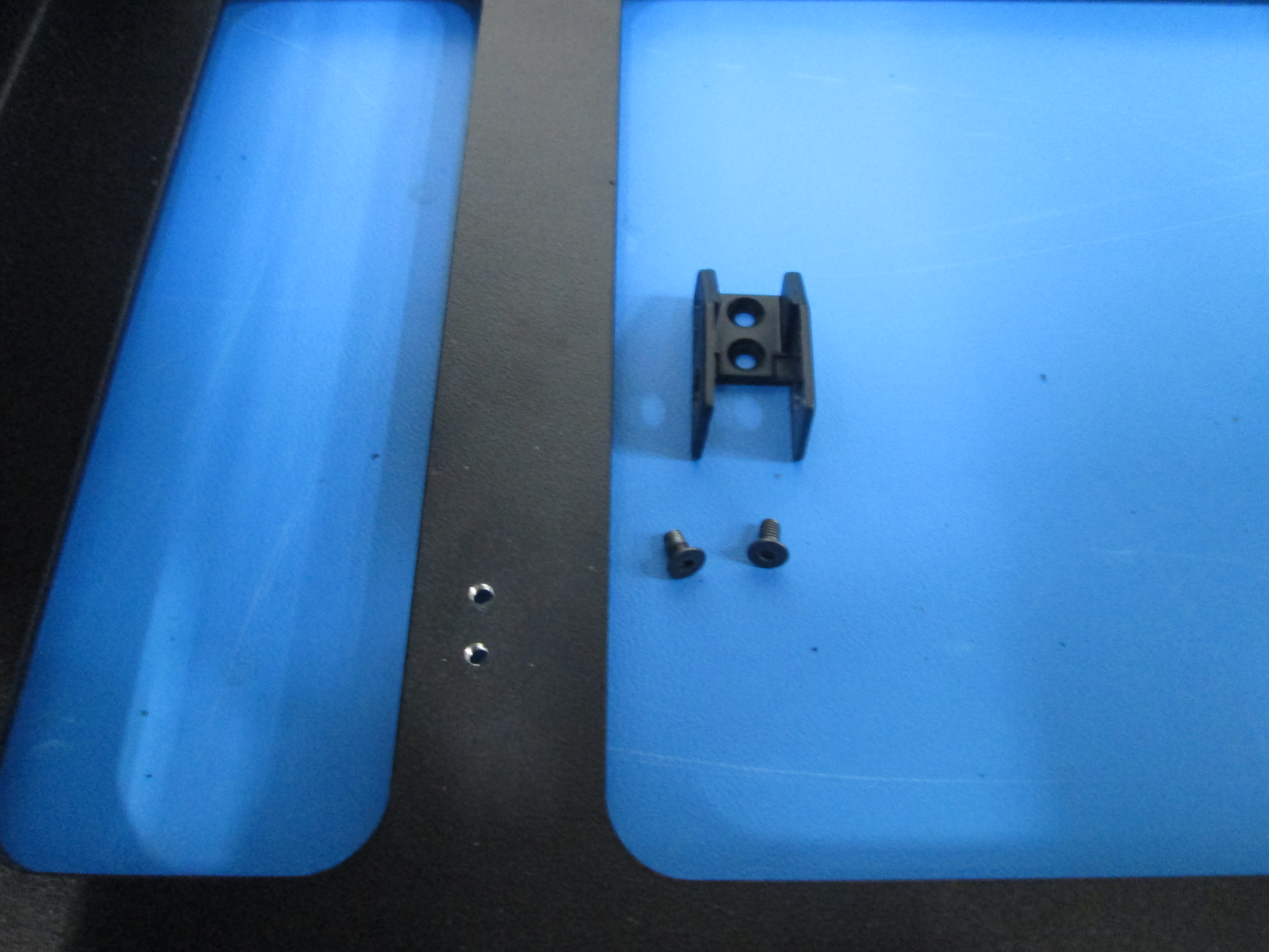
Prep the relief mount by attaching the female cable guide connector using 2x M3x6 flat head screws as shown, note orientation.
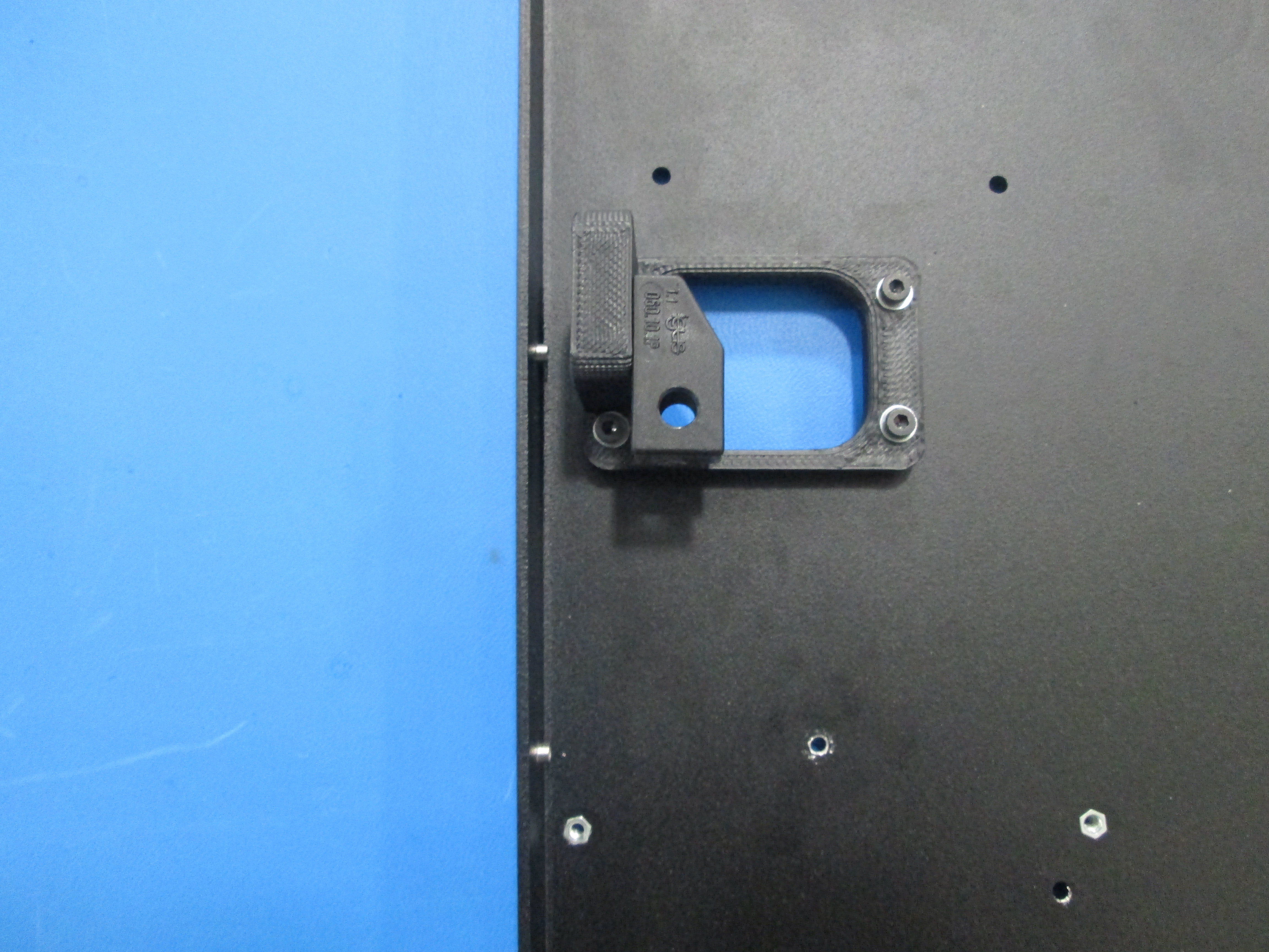
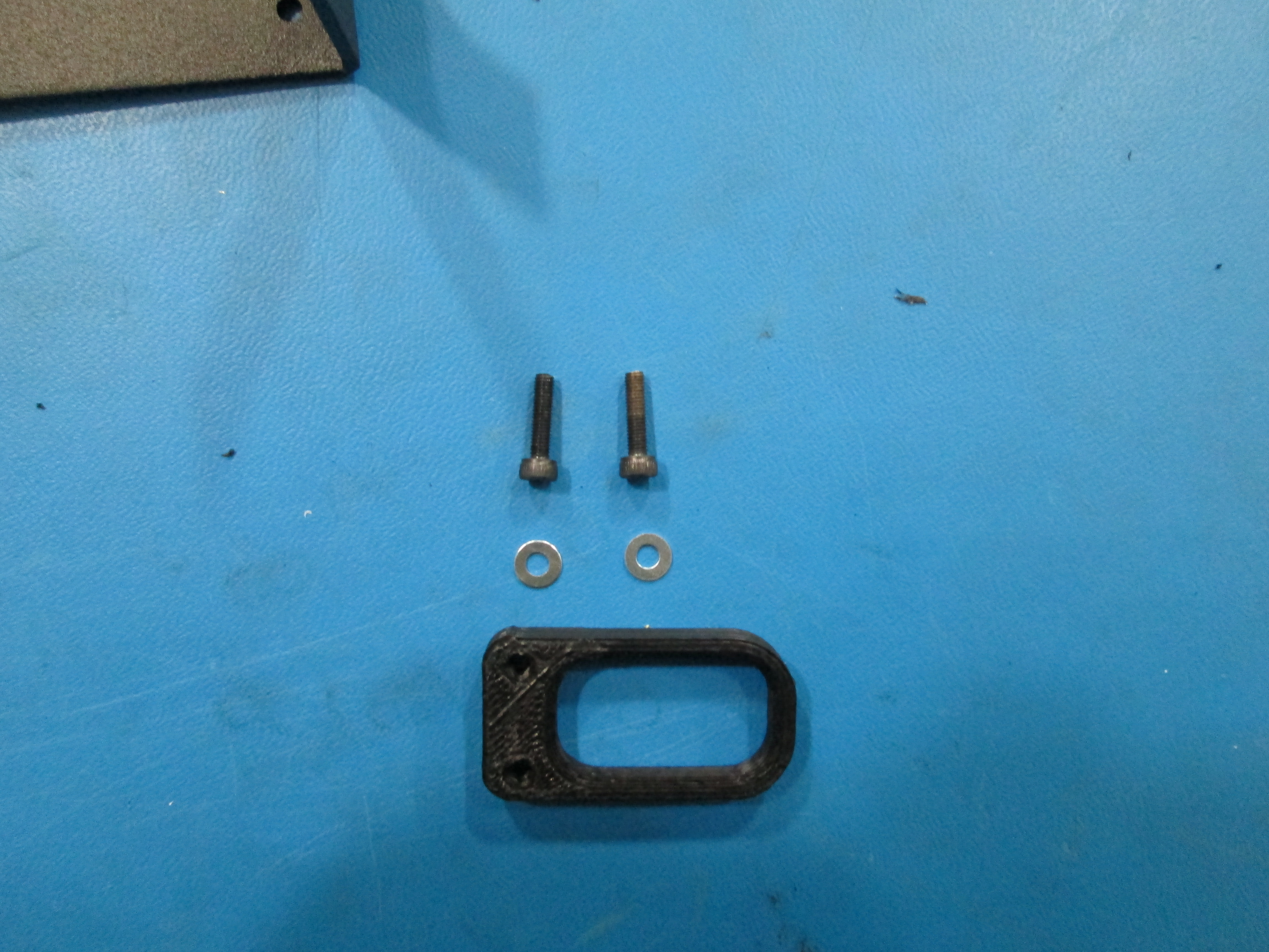
Mount the relief mount to the left plate using 3x M3x12 SHCS with M3 washers as shown, note orientation.

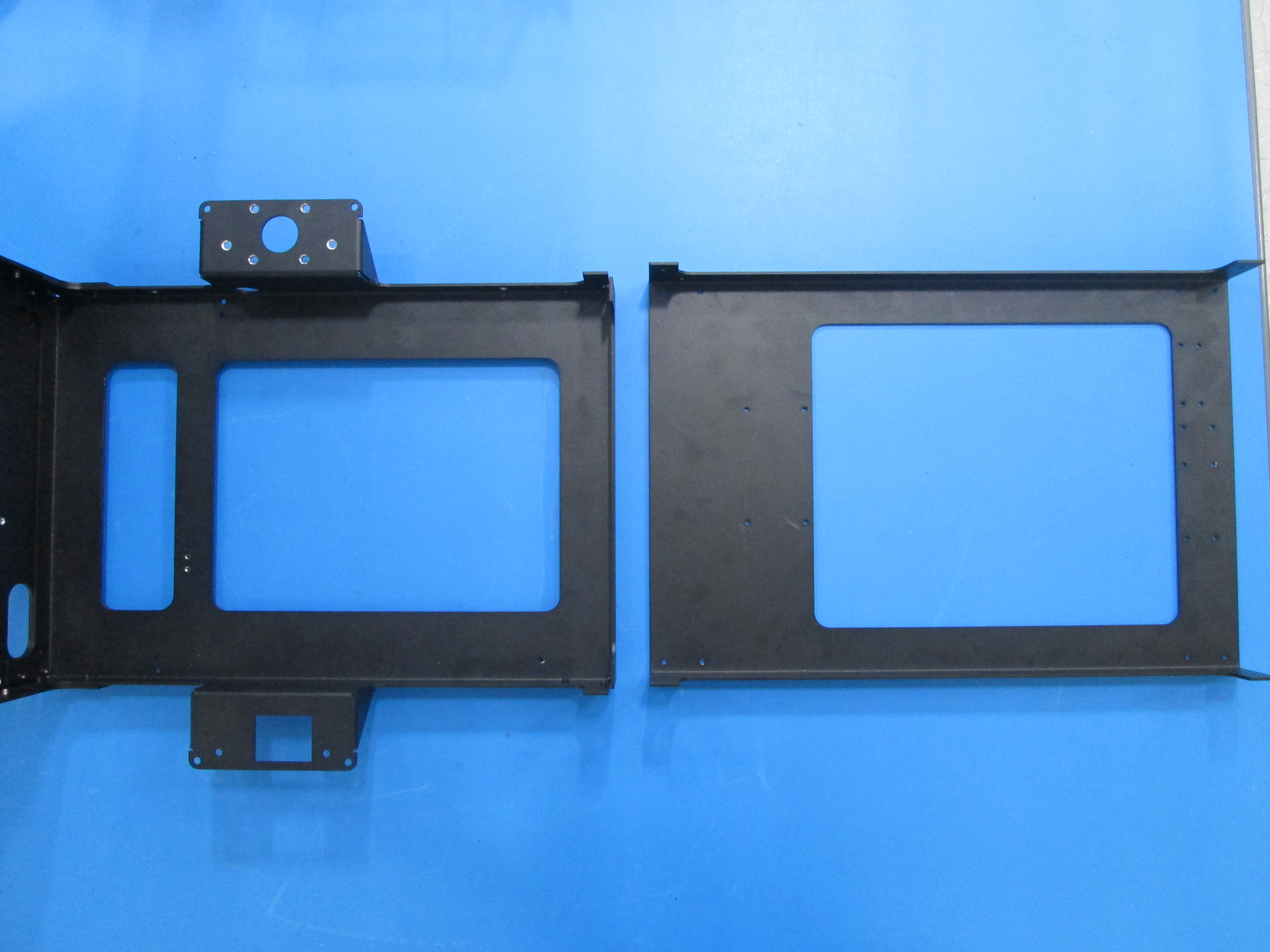
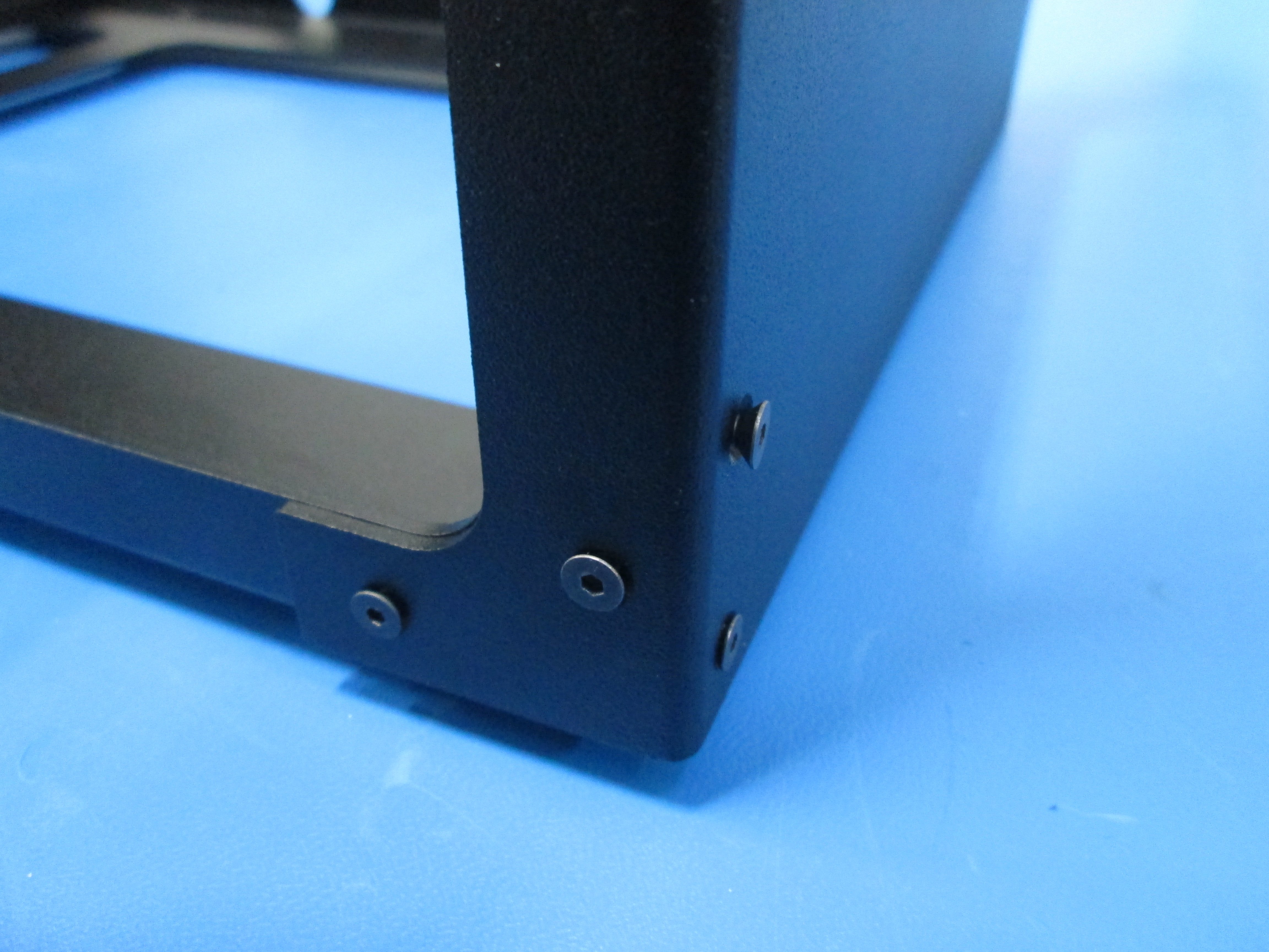
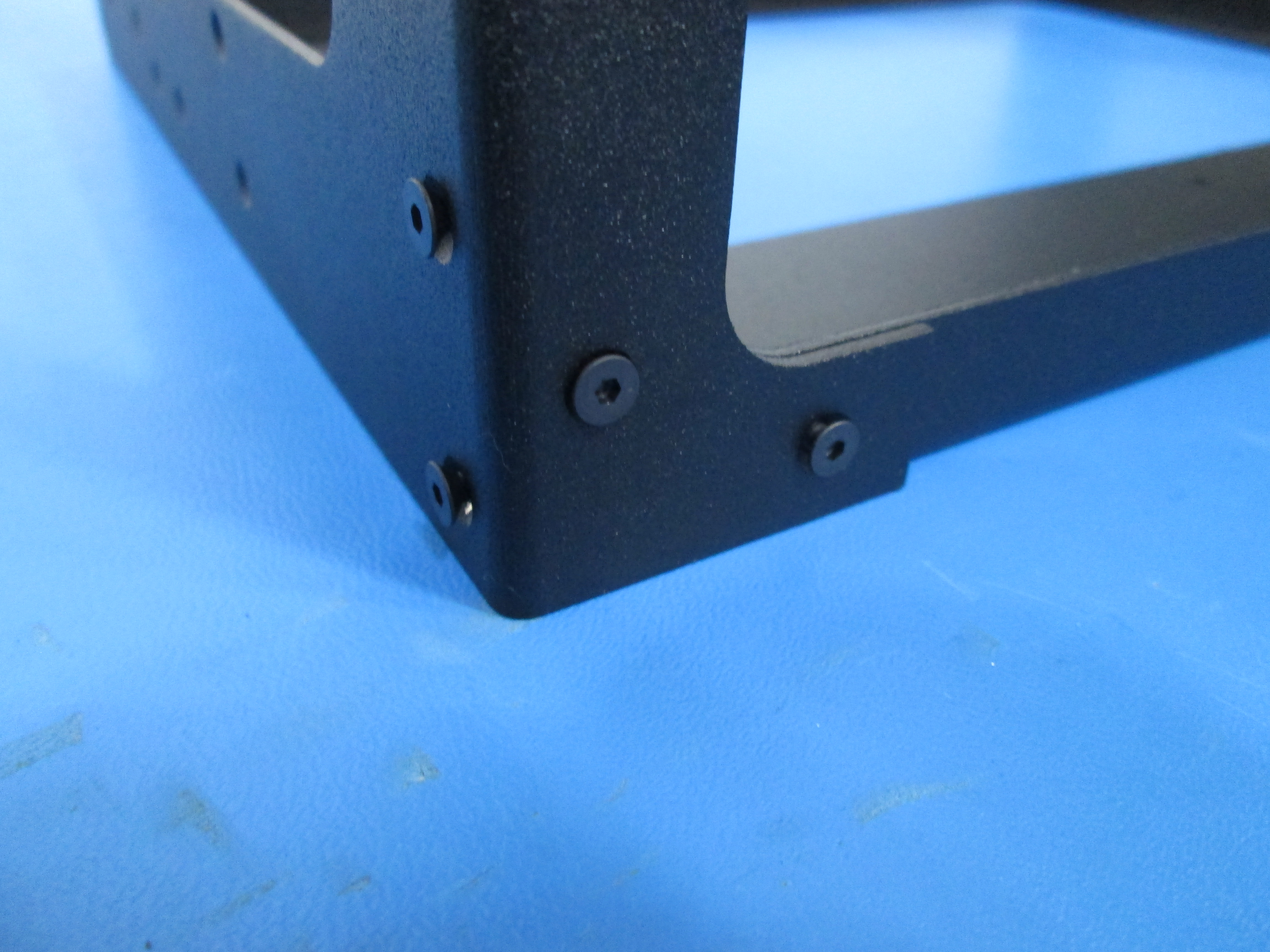
Attach the left plate to the bottom plate using 8x M3x6 flat head screws as shown, noting orientation.
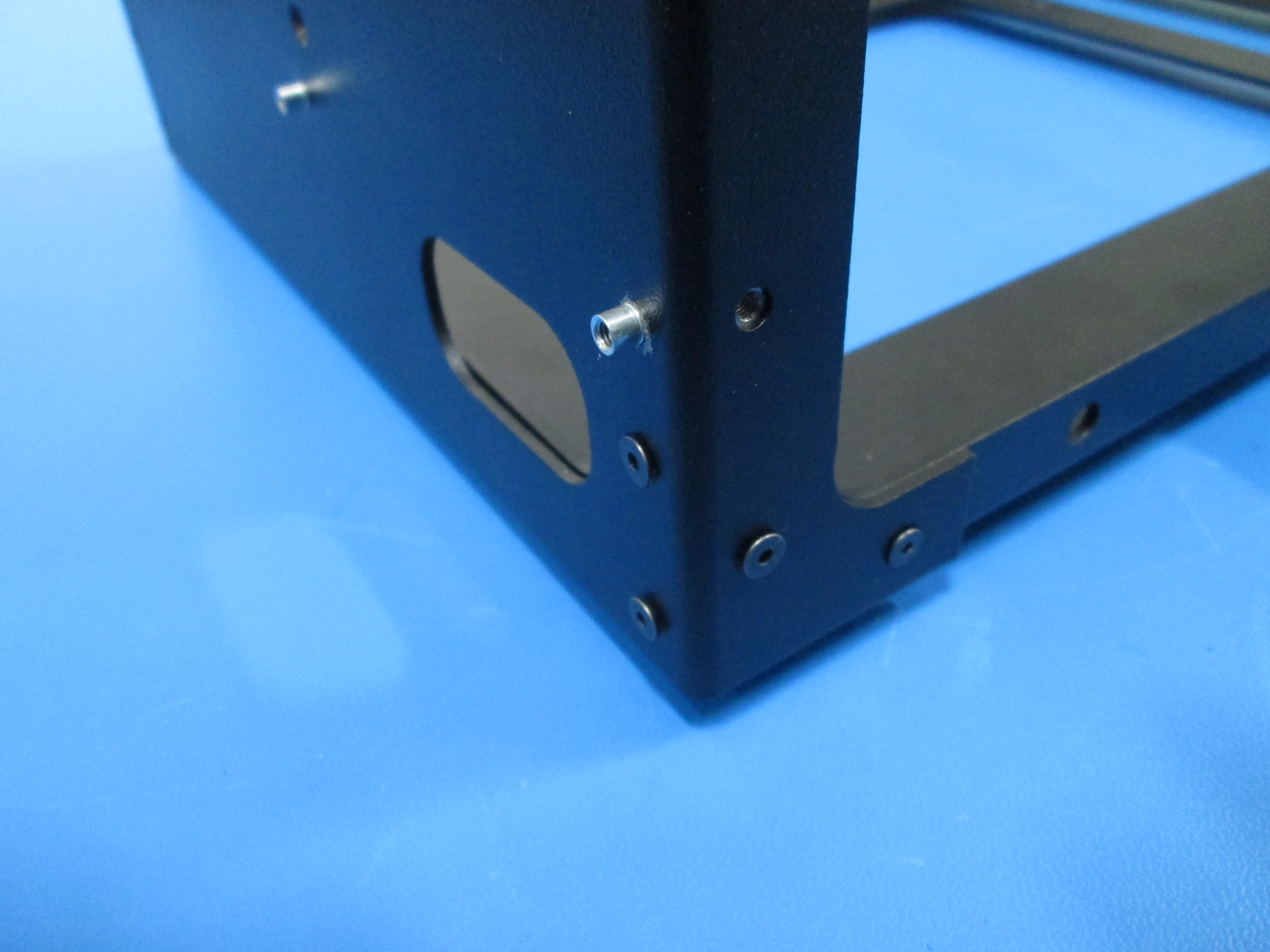
Next attach the lower relief mount using 2x M3x12 SHCS and M3 washers. Note orientation.
Start the screws but leave them loose for now.
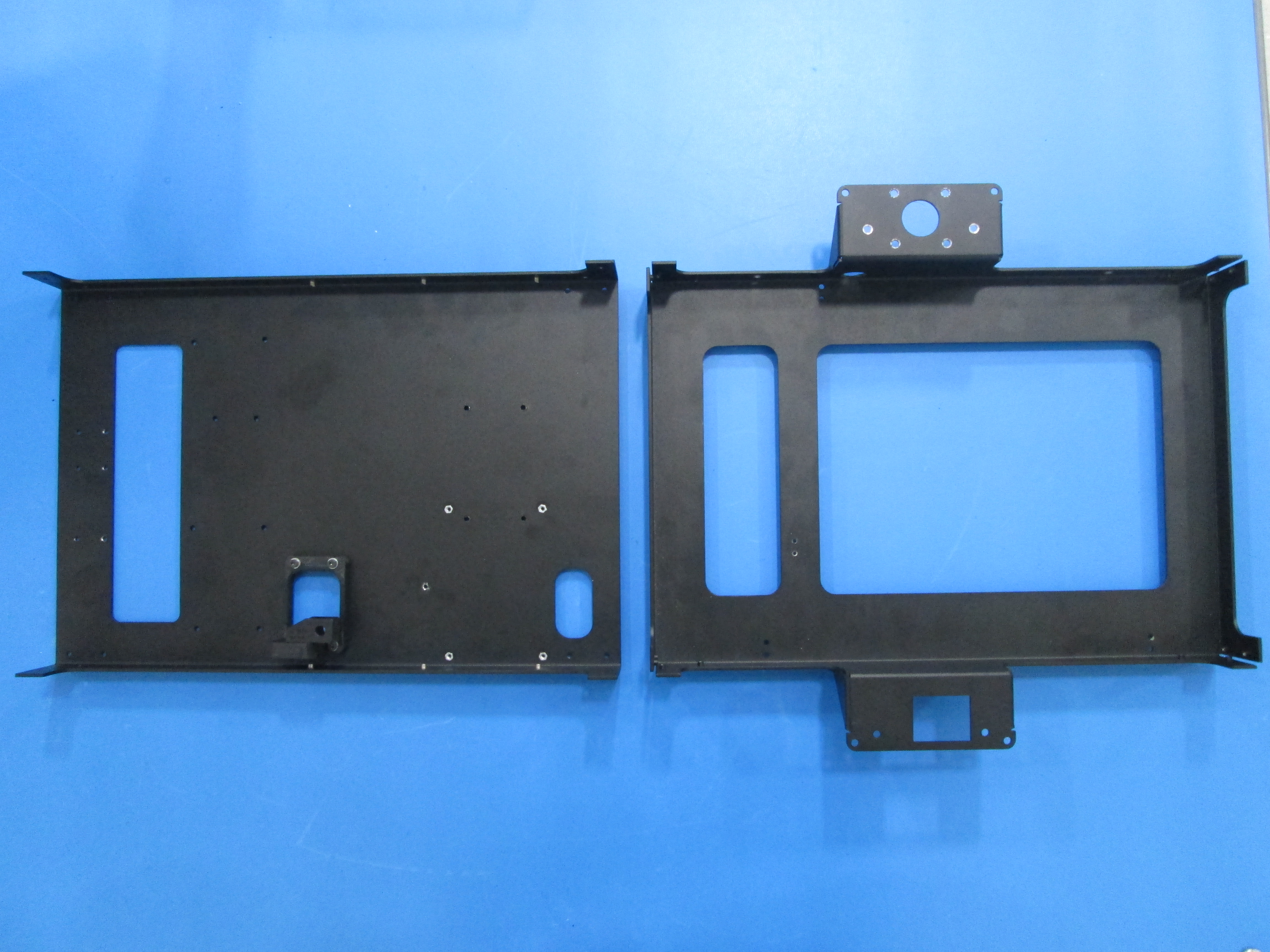

Attach the right plate to the bottom plate using 8x M3x6 flat head screws as shown, noting orientation.
Leave the screws loose for now.
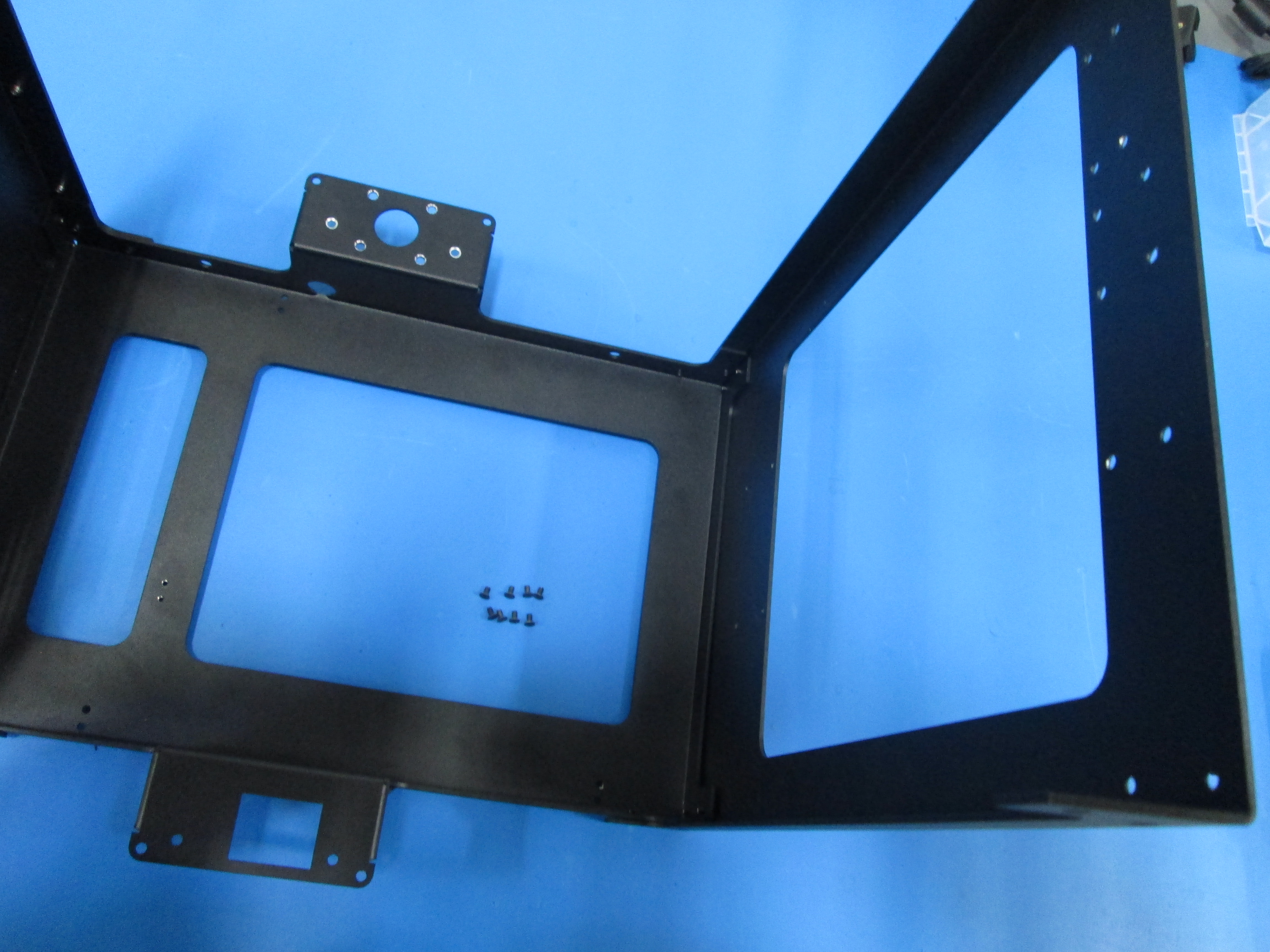
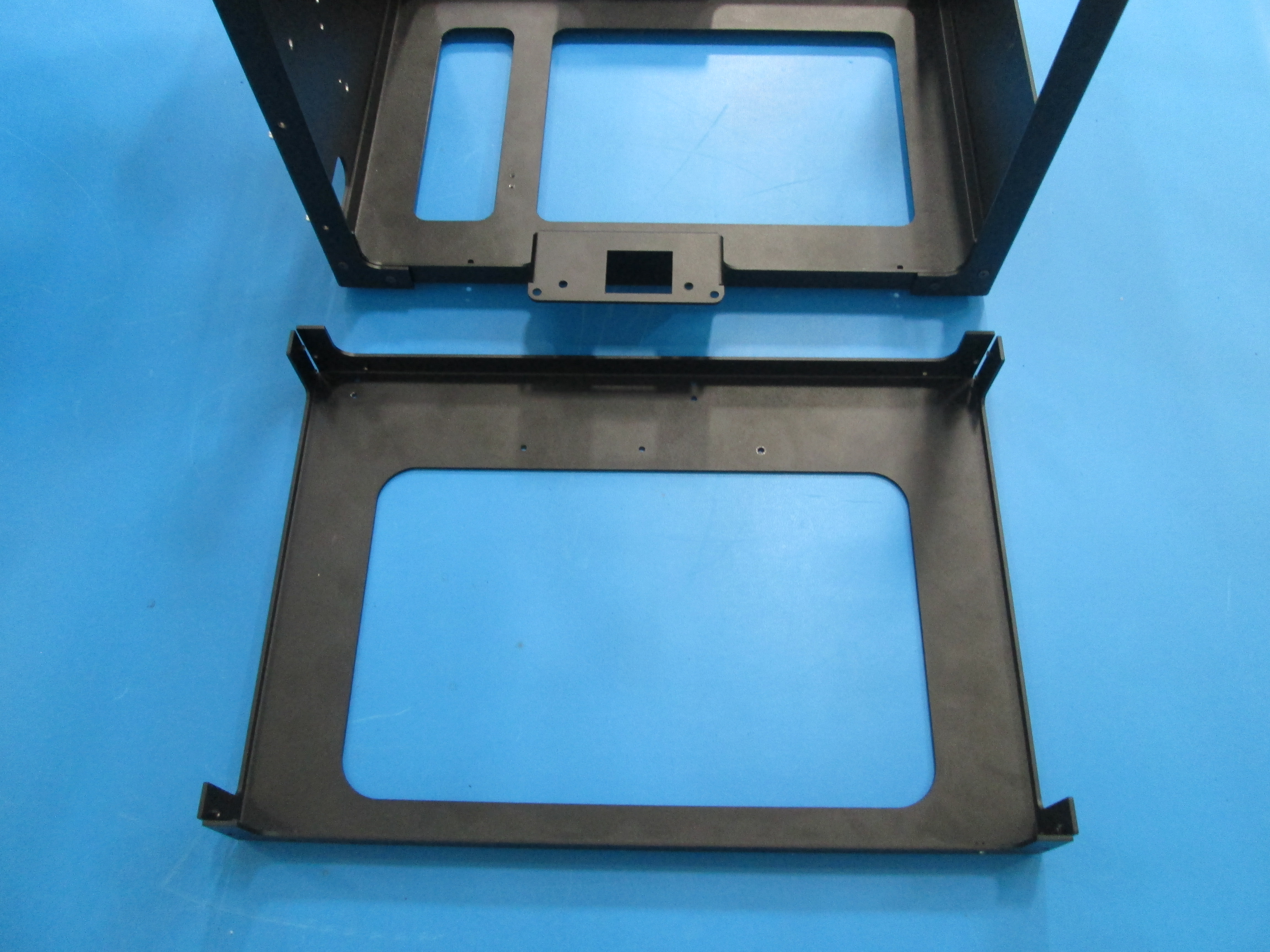
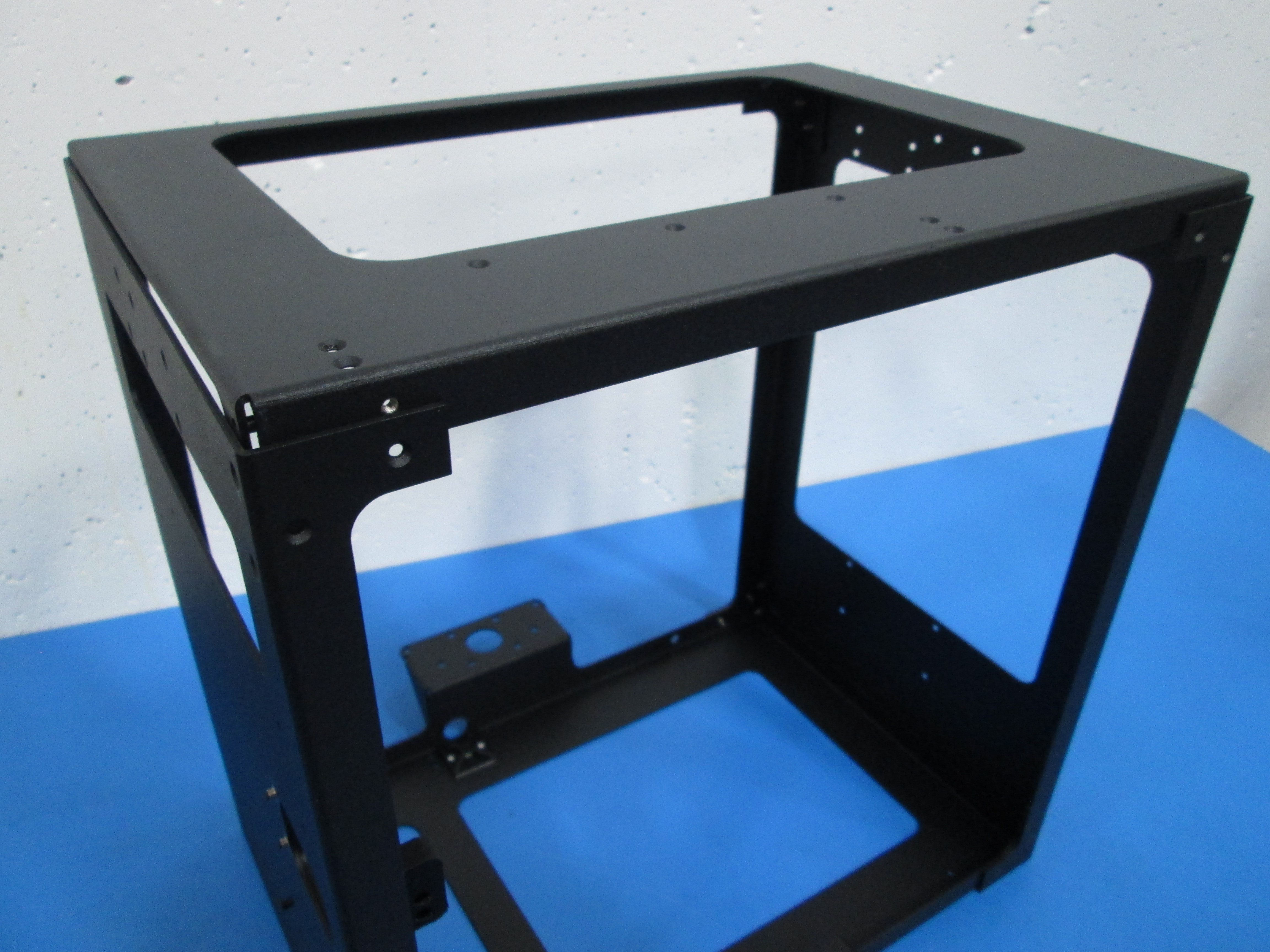
Attach the top plate to the left and right plates.
Once the top plate is in position, flip frame assembly upside down so that the top is facing down.
Using 16x M3x6 flat head screws as shown, attach the top plate while making sure that the frame assembly is squared. Note orientation.
Note, if you are using the hand drill DO NOT put the torque setting over 2.
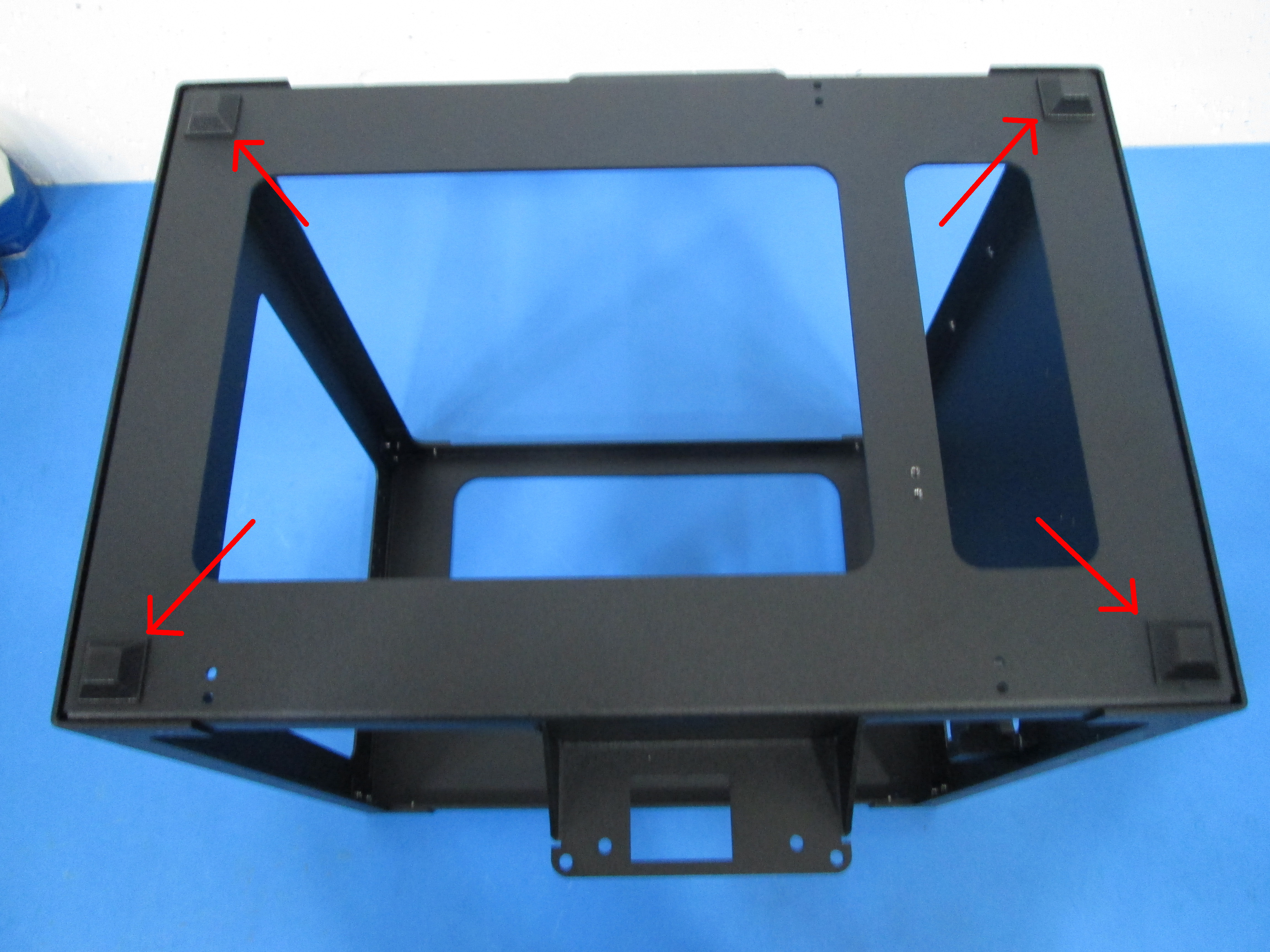
Add 4x rubber feet to the bottom of the bottom plate as shown.
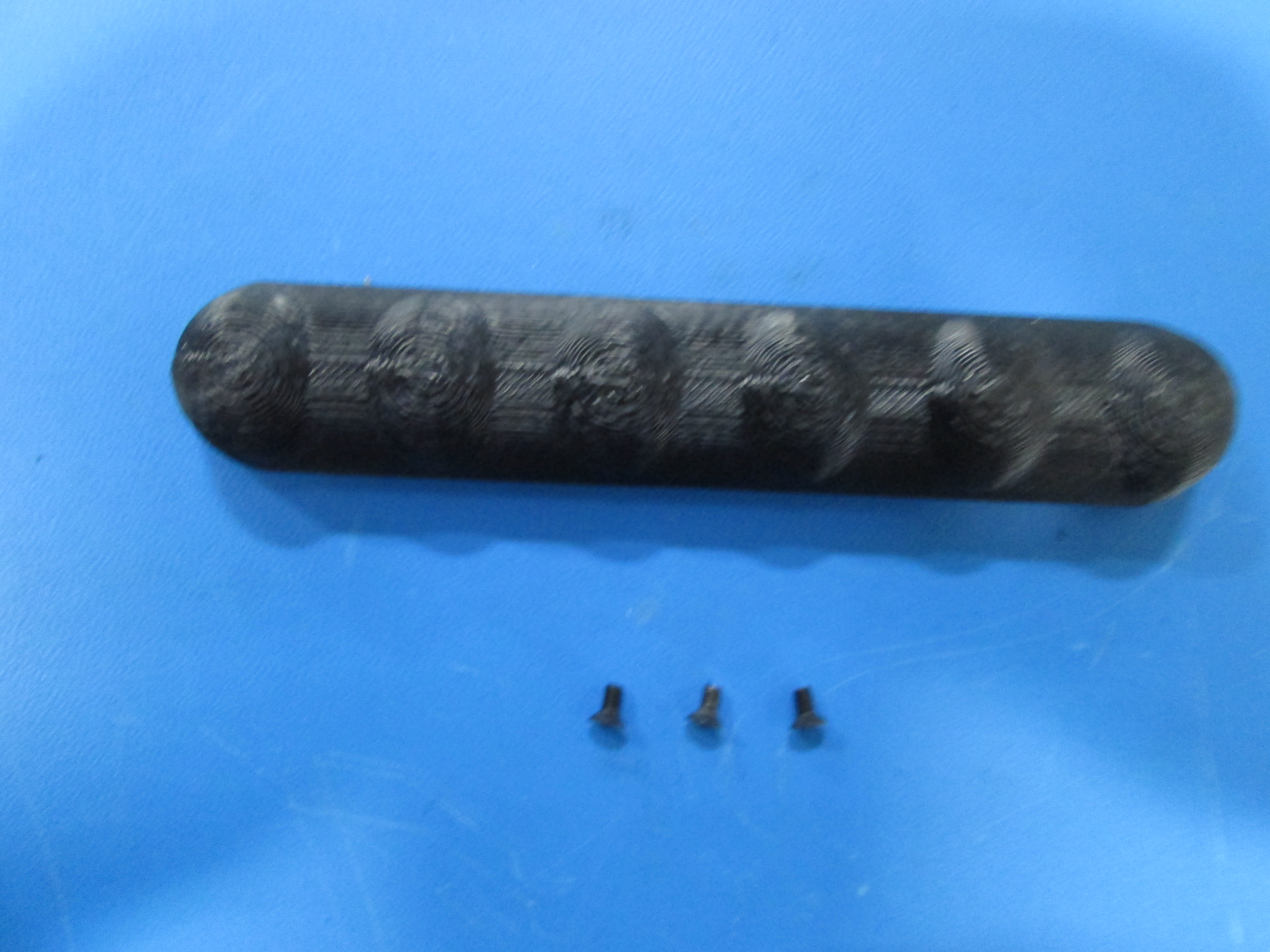
Attach the handle to the top plate using 3x M3x6 flat head screws as shown.
DO NOT use the drill for those screws.

Attach the female cable guide connector to the bottom plate using 2x M3x6 flat head screws as shown, note orientation.

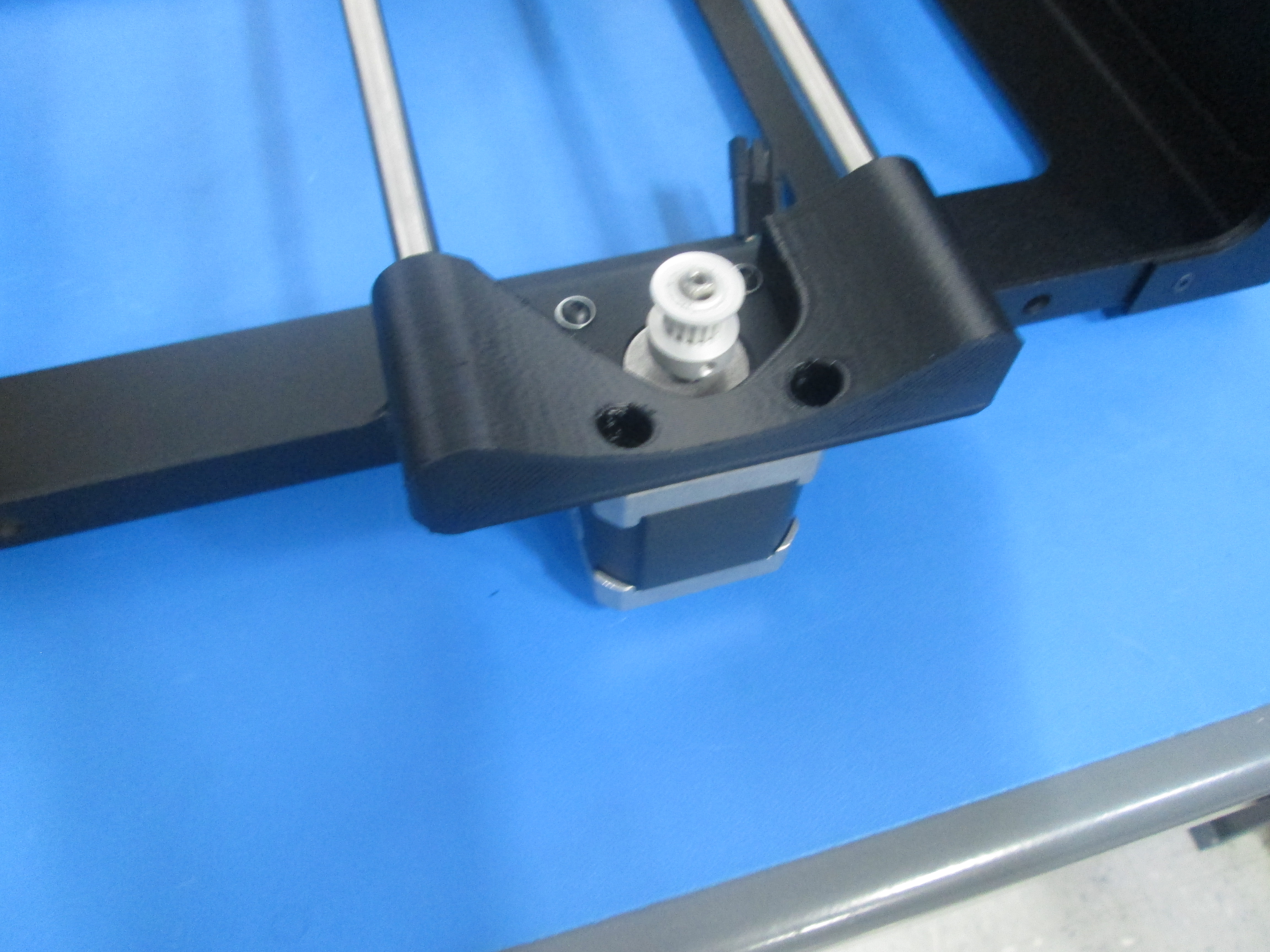
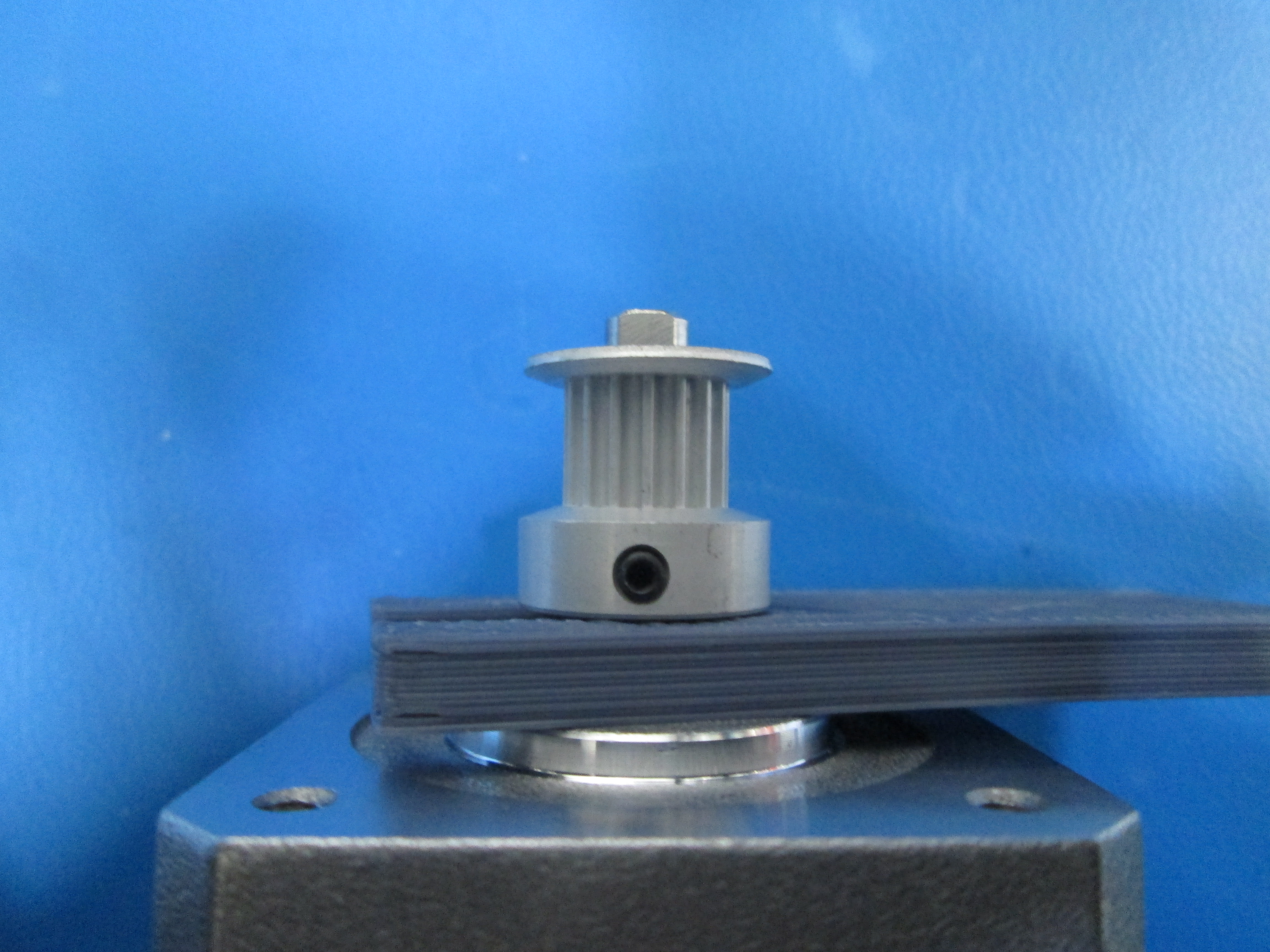
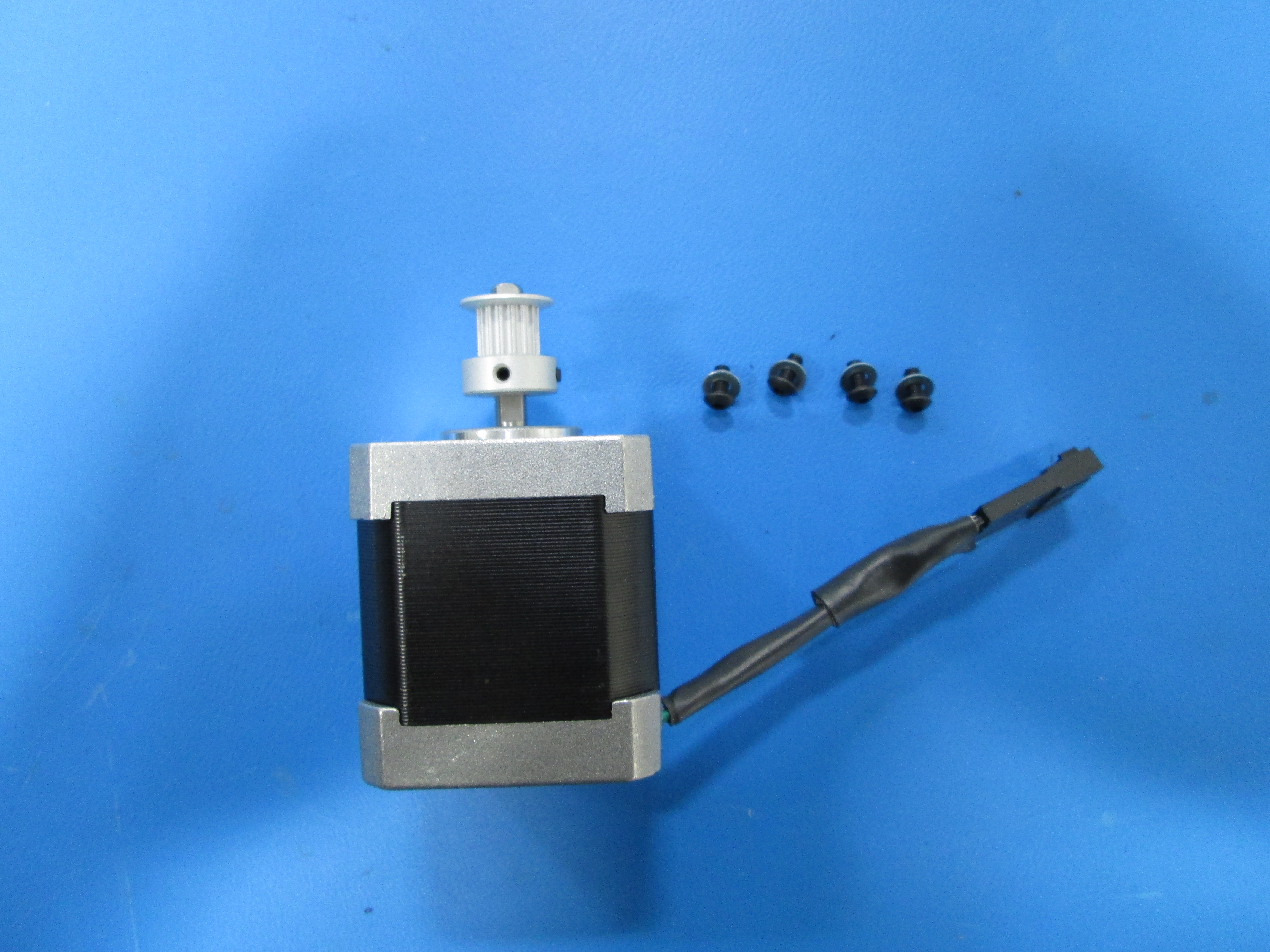
Prep the motor by putting the pulley on using the fixture to set the height. Make sure one of the set screws is on the flat of the motor and tighten both.
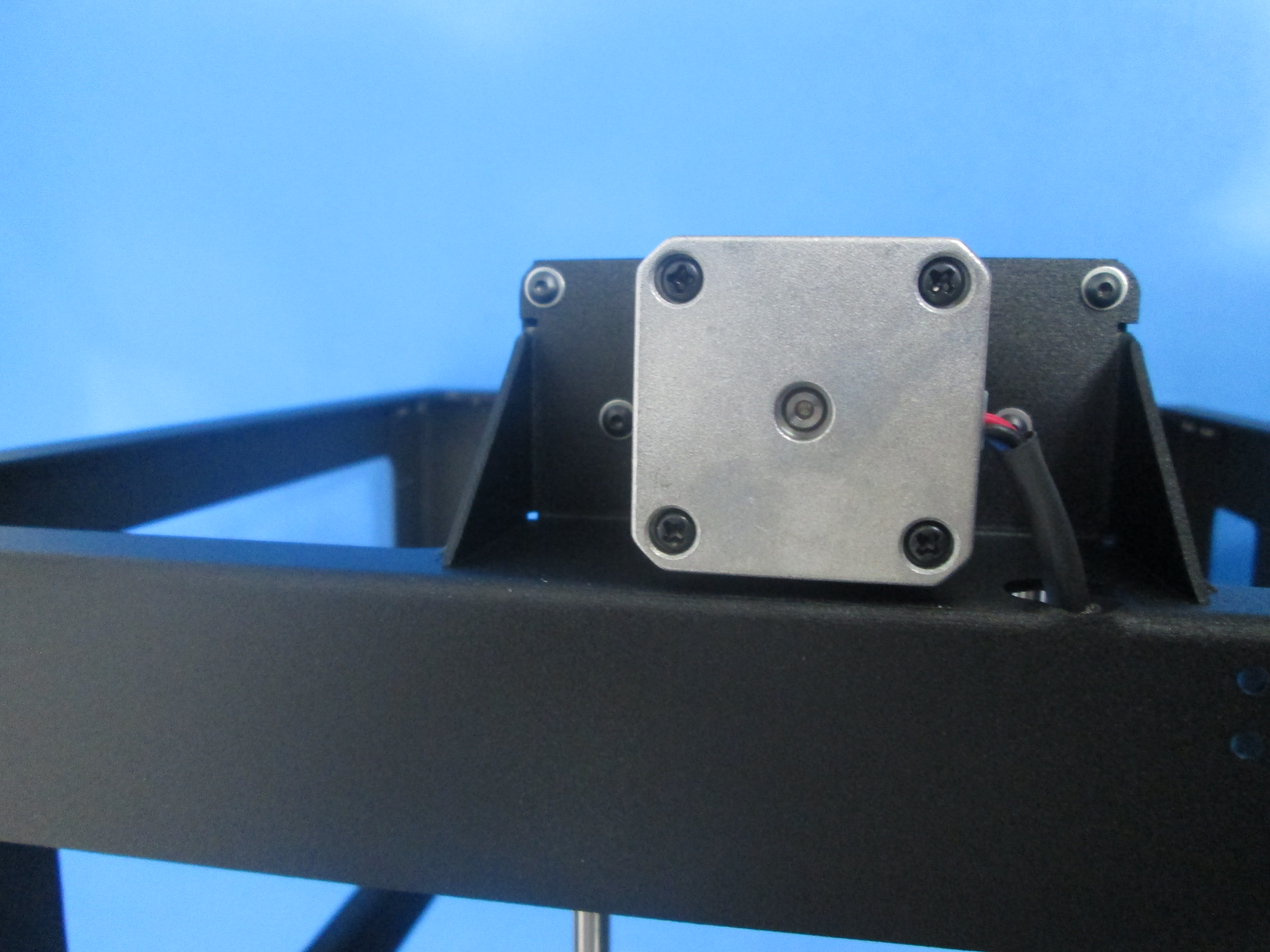
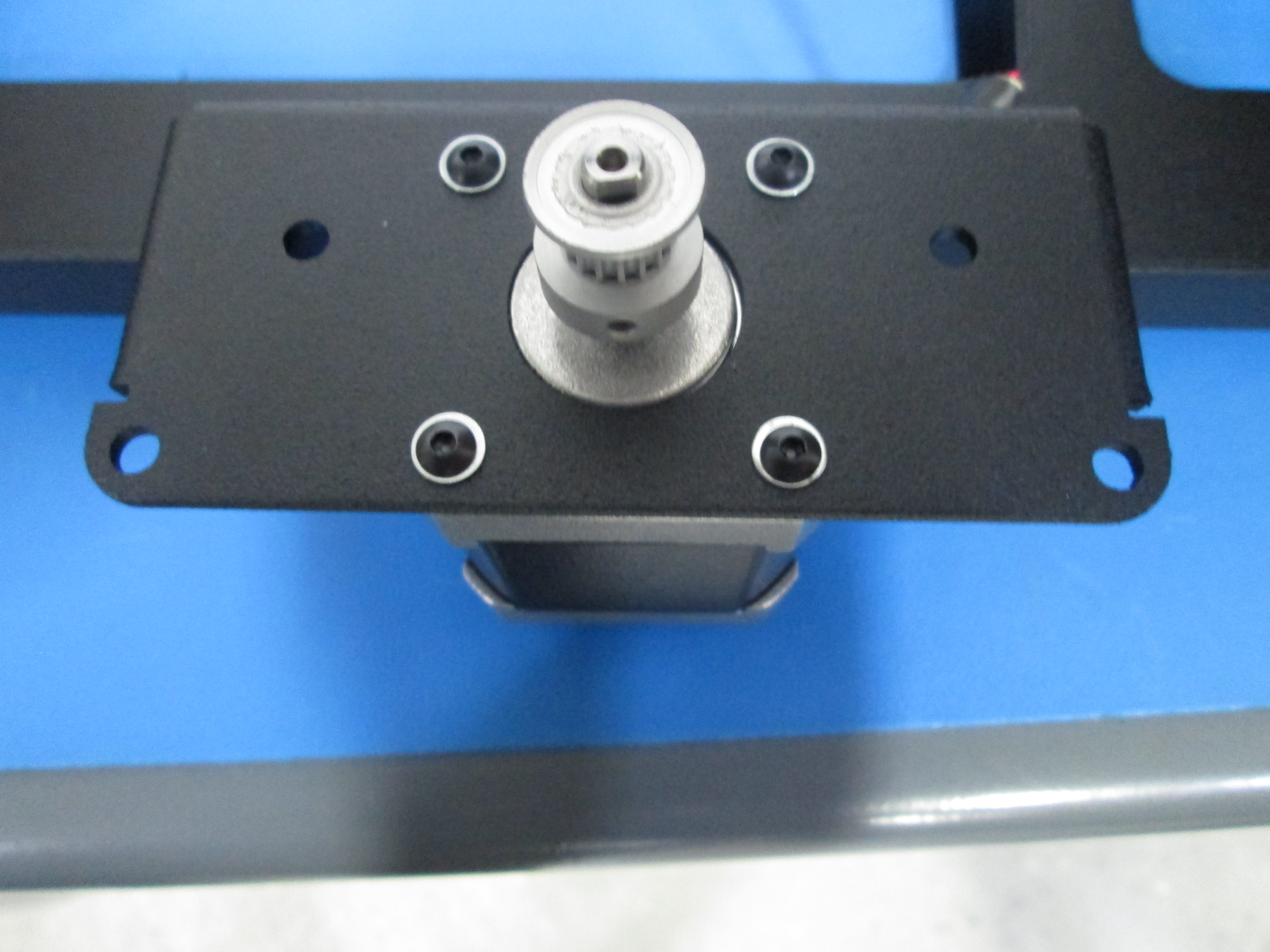
Attach the motor to the side of the frame with the circle cut out using 4x M3x6 BHCS ball head screws and M3 washers as shown, note orientation of motor.
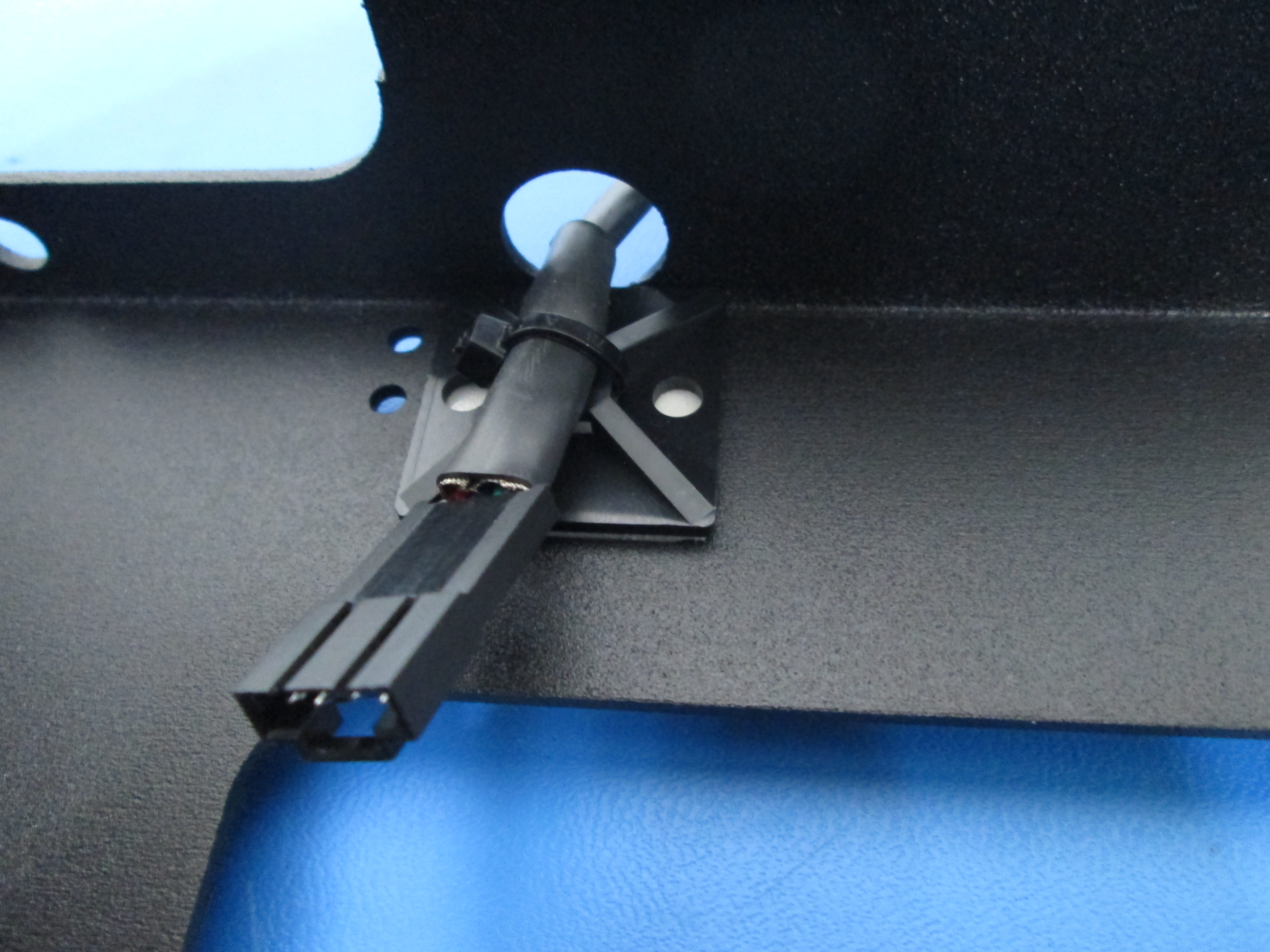
Zip tie motor wire to the inside of the fame as shown.

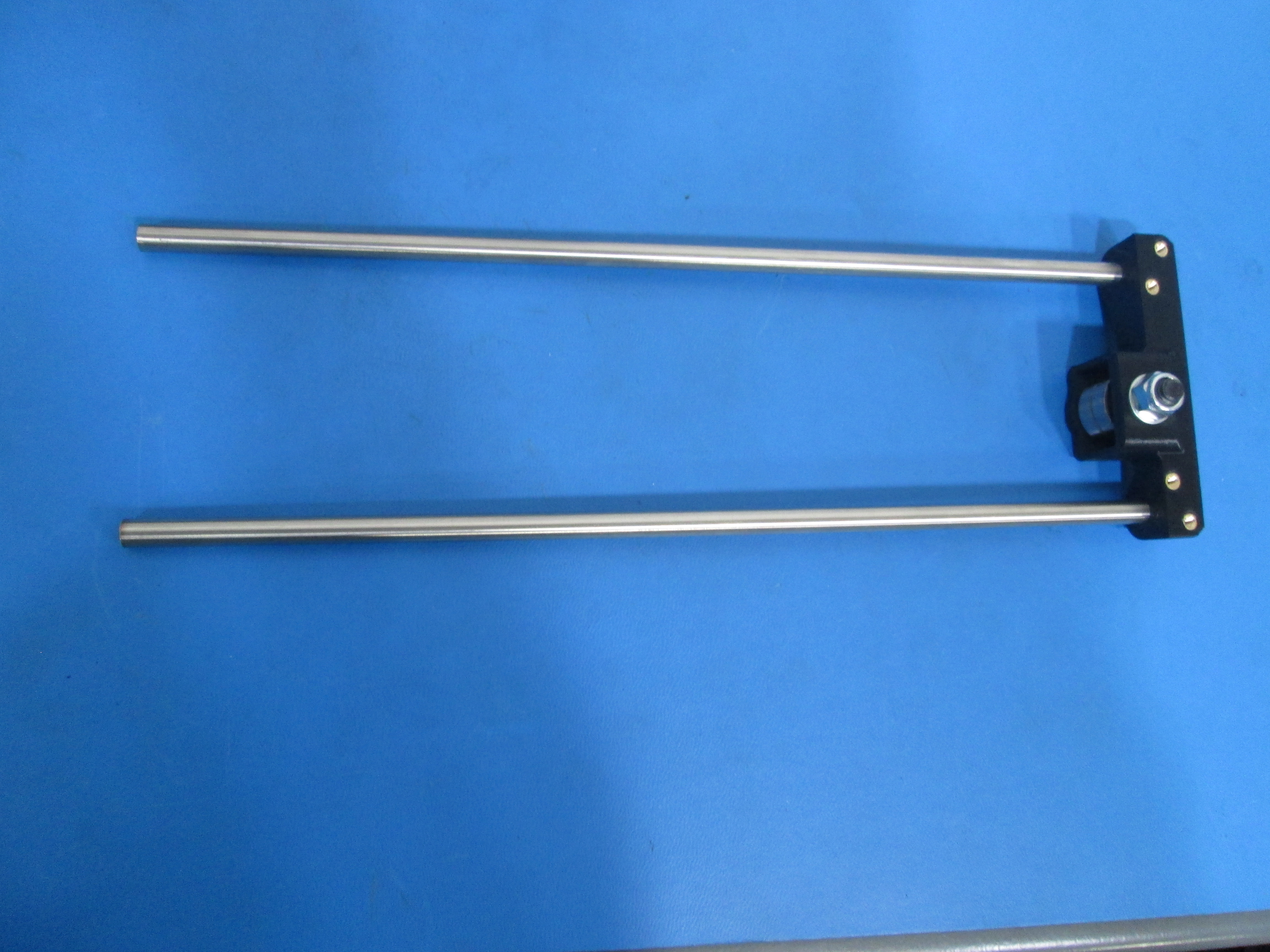
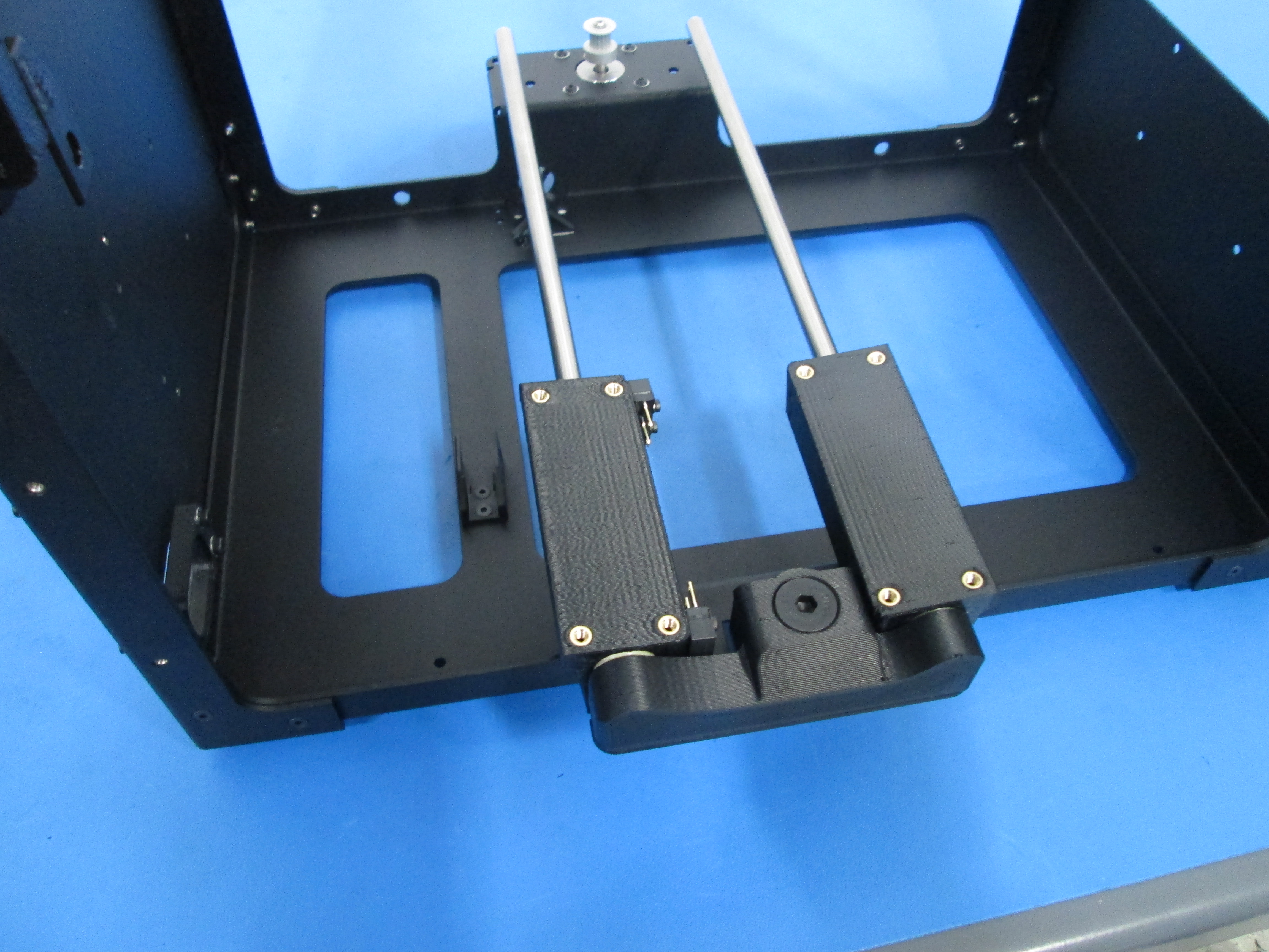
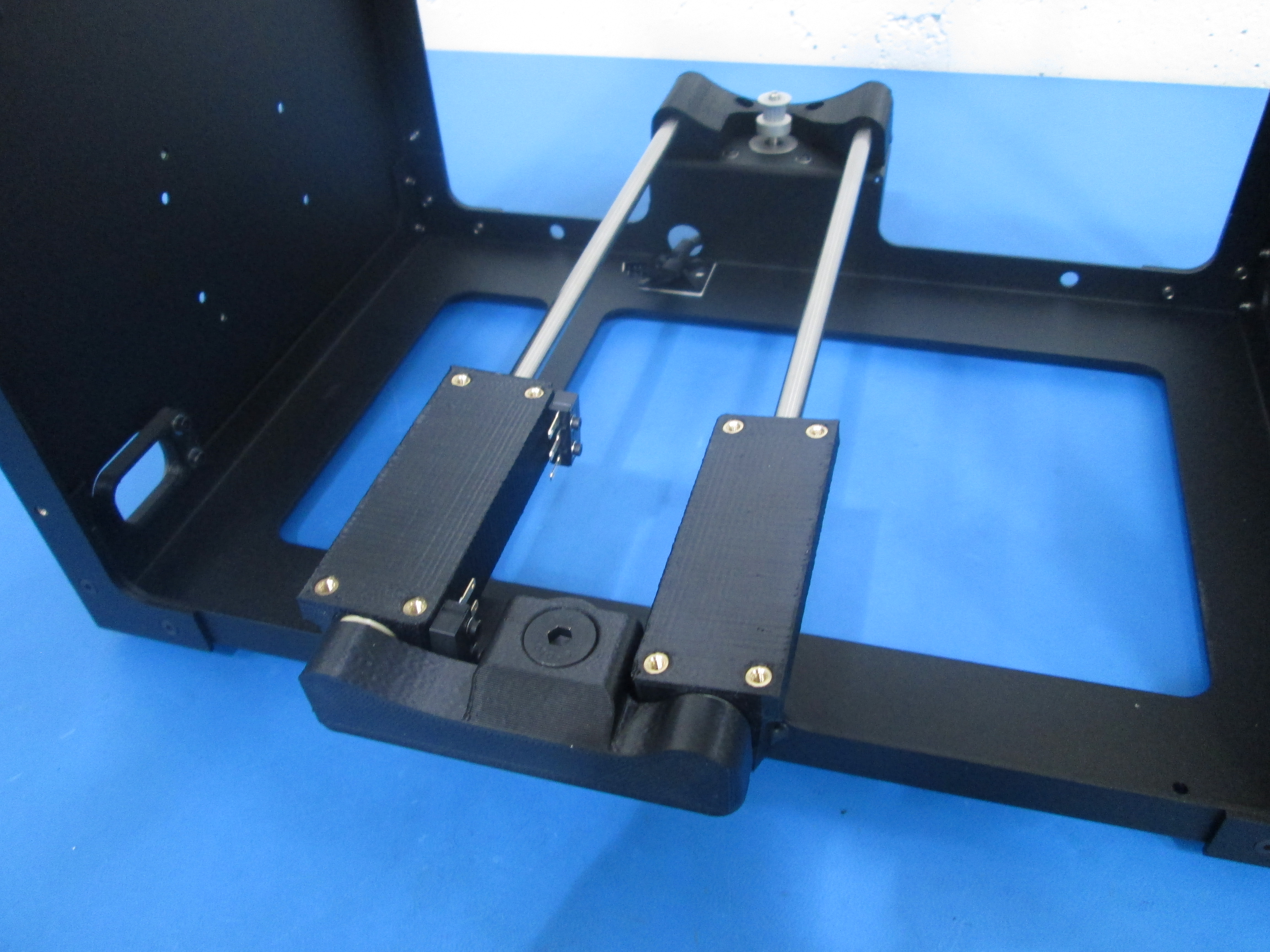
Slide 2x smooth rods into the Y idler mount as shown.
Slide 2 smooth rods into the Y idler end as shown.
Using 4 3x6 BHCS and M3 washers, attach Y idler with smooth rods to the frame as shown.
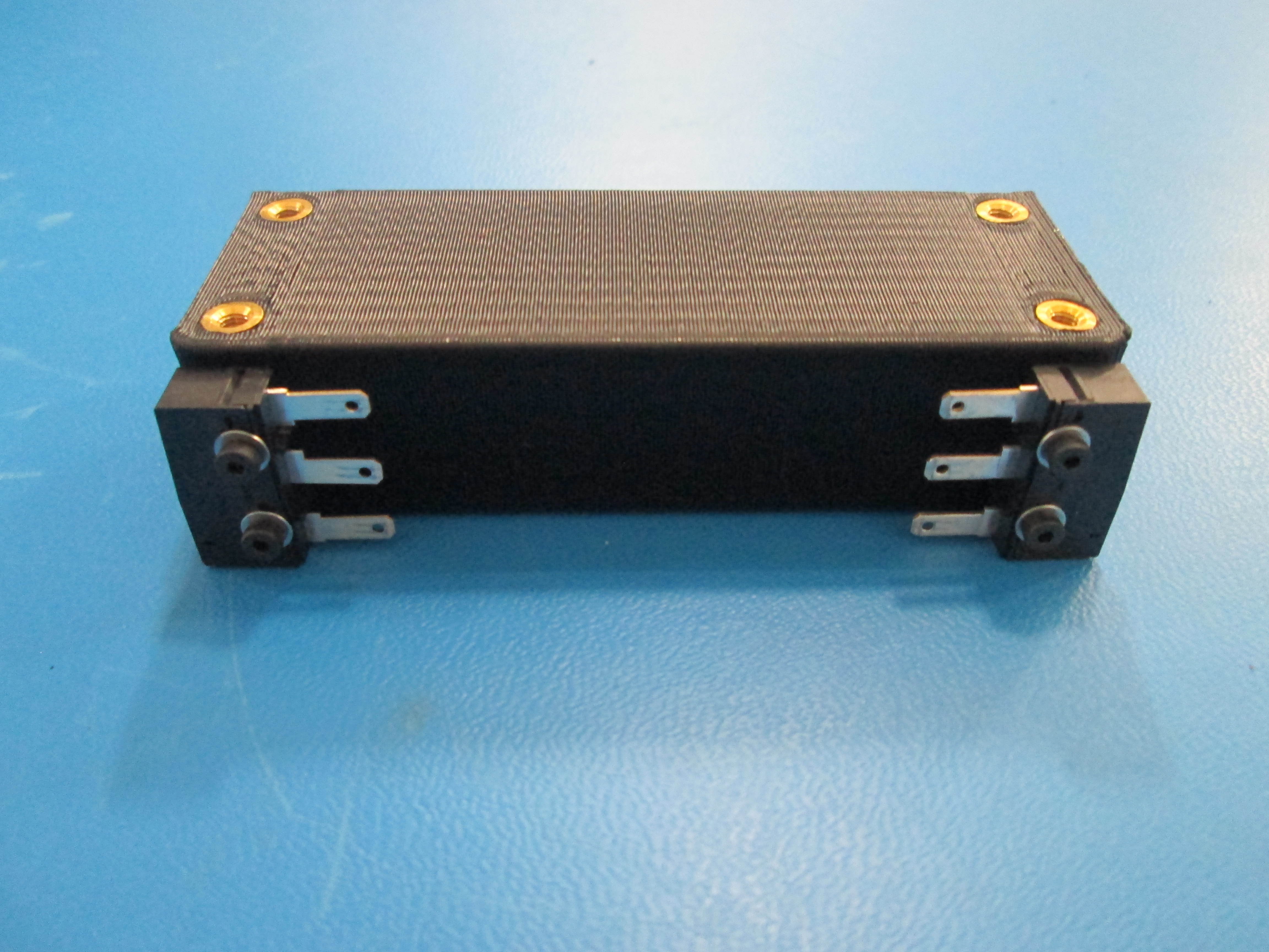
Slide the two bearing holders onto the rods, note orientation.
Slide the bearing that has the switches on it back and forth making sure the switch can make contact with the ends.
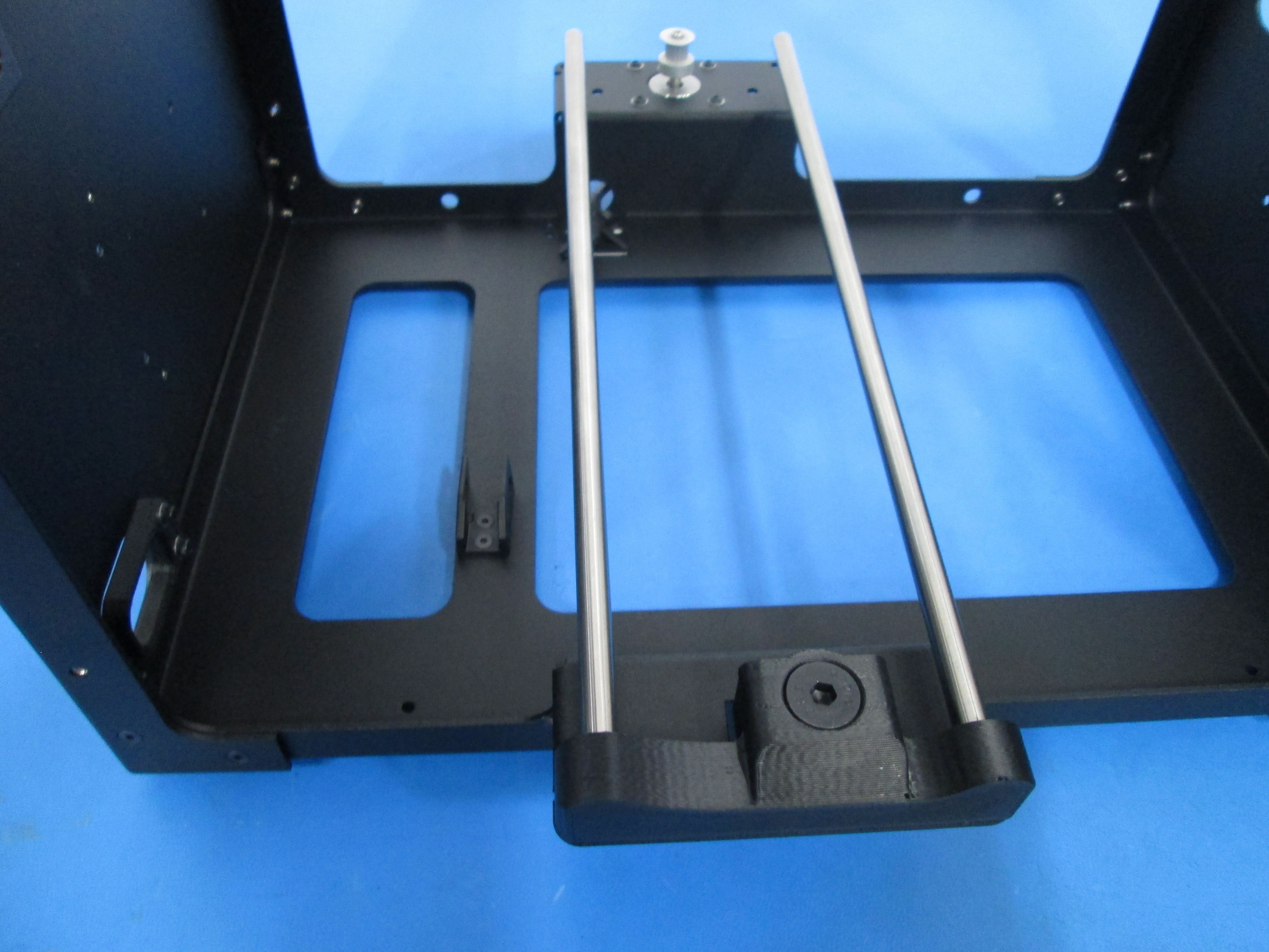
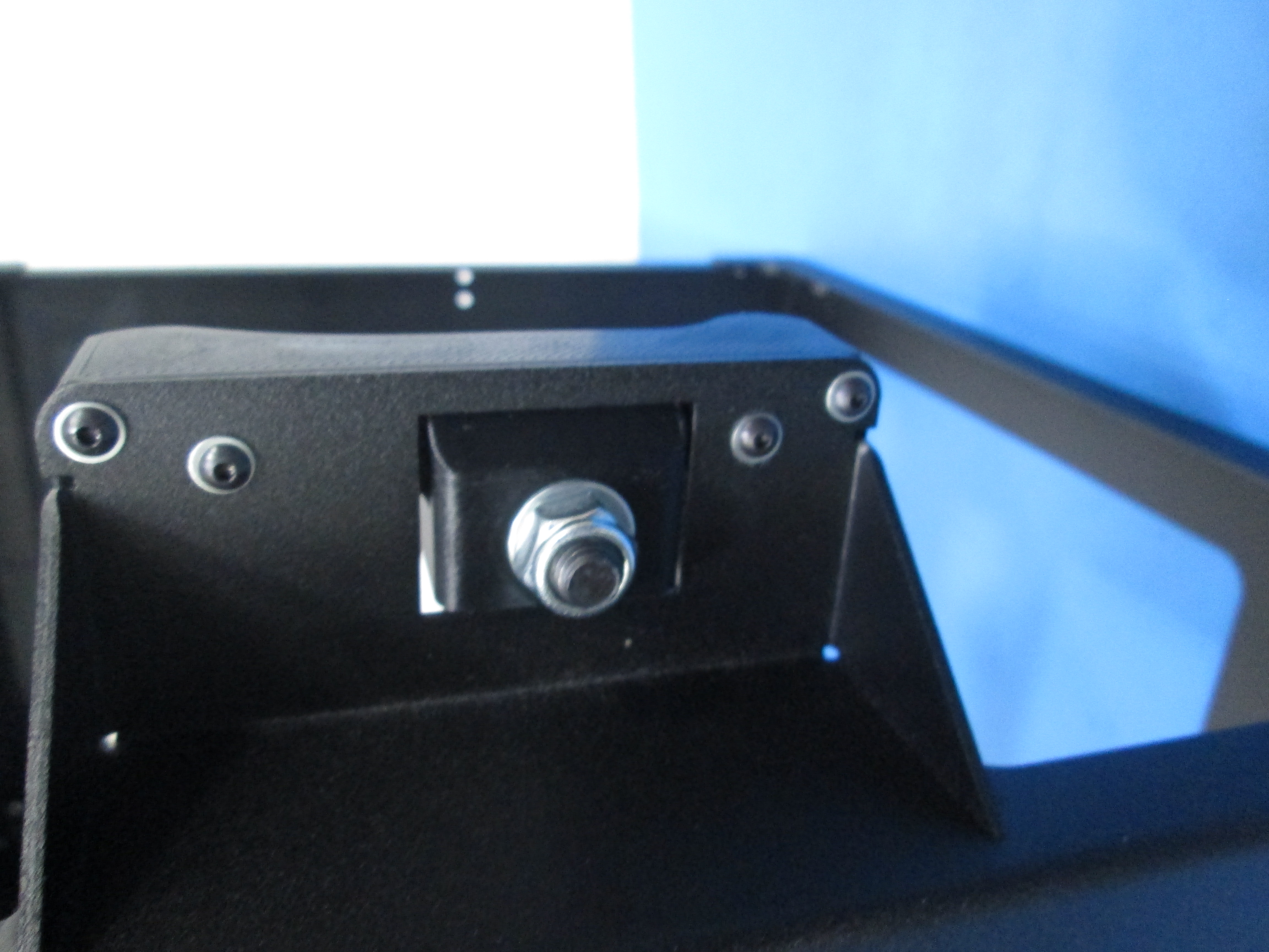
Slide the Y motor rod mount onto the smooth rods and secure it to frame using 4 3x6 BHCS and M3 washers. Make the rod mount flush with the frame.