Open HardwareAssembly Instructions
Guides for installation and assembly of the LulzBot line of products made by FAME 3D LLC.
Guides for installation and assembly of the LulzBot line of products made by FAME 3D LLC.
Qty Part Number Description
-1x PC-AS0041 Plastic Laser Cut LCD cover for UL
-1x EL-HR0074 Cable Harness, DC Power Harness v1.0 TAZ6
-1x EL-HR0075 Cable Harness, X Harness
-1x EL-HR0076 Cable Harness, TAZ 6 CB Switch to PSU white
-1x EL-HR0077 Cable Harness, TAZ 6 CB Switch to PSU Black
-1x EL-HR0078 Cable Harness, TAZ 6 plug to ground green
-1x EL-HR0079 Cable Harness, TAZ 6 CB PS to Ground
-1x EL-HR0080 Cable Harness, TAZ 6 CB Plug to Switch Harness
-1x EL-HR0081 Cable Harness, TAZ 6 CB Bed Harness Internal
-1x EL-HR0082 Cable Harness, TAZ 6 Bed Power Harness Internal
-1x EL-HR0083 Bed Power Harness External, TAZ6
-1x EL-HR0084 Cable Harness, TAZ 6 CB X Harness
-1x EL-HR0087 Cable Harness, TAZ 6, Extruder 0 harness internal
-1x EL-HR0088 Cable Harness, TAZ 6 CB Y-Z Harness
-1x EL-HR0091 Cable Harness, TAZ 6 Y-Z Harness
-1x EL-HR0092 Cable Harness, TAZ 6 External Harness
-1x EL-HR0101 Cable Harness, TAZ 6, CB Dual Extruder Harness
-2x AS-CB0068 Cable Harness, CB LCD Harness v2
-1x EL-FA0036 Pelonis FAN 24V 80x15mm Low flow
-1x EL-MS0144 connector cover
-1x EL-MS0346 MOD PWR ENTRY INLET W/FUSE 6A - IEC C14 Receptacle – AC Filter 6A 250VAC
-2x EL-MS0347 Fuse Ceramic 6.3A 250VAC 5X20MM
-1x EL-PS0031 Mean Well Switching Power Supplies 504W 24V 21A Power Supply W/PFC
-1x EL-SW0023 SWITCH ROCKER DPST 20A 250V, illuminated red
-1x PC-AS0056 LCD LB_GLCD
-1x PC-BD0094 RAMBO Electronics v1.4a
-6x HD-BT0053 Screw, Flat Head Phillips Machine 18-8 SS 4-40 x 1/4 Black Oxide Finish
-4x HD-BT0054 Screw, Socket Head Cap, M2.5 x 12MM, Black Oxide
-4x HD-BT0104 Screw, Button Head Cap, M3 x 8 SST
-2x HD-BT0116 Black Alloy Steel Flat-Head Socket Cap Screw, Class 10.9, M3 Size, 10mm
-14x HD-BT0137 Screw, Button Head Cap, M3 x 8 Black-Oxide
-6x HD-BT0146 Screw, Button Head Cap, M3 x 12 Black Oxide
-5x HD-BT0155 Screw, Flat Head Socket Cap, M4 x 6 Black Oxide
-4x HD-BT0171 Screw, Button Head Cap, M3 x 20, Black Oxide
-4x HD-MS0058 Wire Tie, 8" Black
-4x HD-MS0249 Cable Tie Holder, 4-Way, Black, Adhesive Backed
-3x HD-MS0336 Bumper, Square, 3/4" Wide, 1/4" High, Black Adhesive-Back
-2x HD-NT0001 Nut, M3, Nylon-Insert, Zinc-Plated Steel
-4x HD-NT0004 M3 nut
-4x HD-WA0013 Washer, Flat, M2.5 screw size
-6x HD-WA0027 Washer, Internal-Tooth Lock, Metric 18-8 Stainless Steel, M3 Screw Size
-24x HD-WA0038 Washer, Flat, 18-8 Stainless Steel, M3 Screw Size, Black-Oxide
-1x PP-FP0075 Laser Etched TAZ 6 Electronics Chassis v0.3 PP-MP0110
-1x PP-FP0076 Laser Etched TAZ 6 Electronics Cover PP-MP0109
-1x PP-FP0078 Laser Etched TAZ 6 Interconnect Cover v0.5 PP-MP0107
-4x PP-GP0089 LCD_spacer
-1x PP-GP0220 Interconnect housing v0.1, TAZ
-1x PP-GP0230 LCD bezel
-1x PP-GP0435 Flexy LCD Knob
-1x PP-GP0235 SD Card bezel
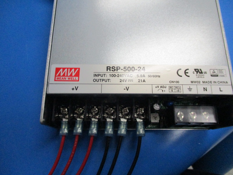
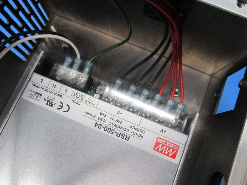
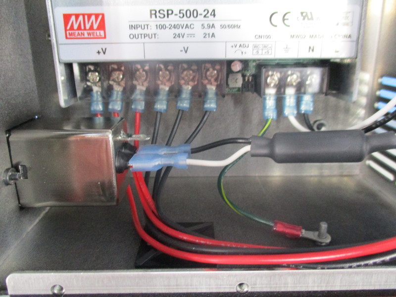
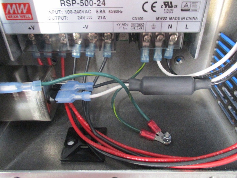
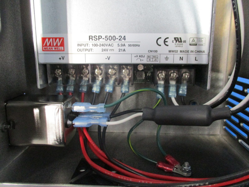
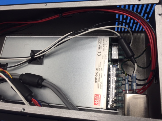
Connect EL-HR0074 CB DC Power Harness (3 red (+3) and 3 black (-3)) to power supply. Secure screws to finger tight then ¼ turn past.
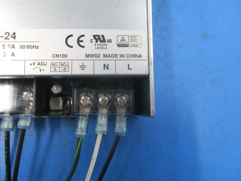
Connect EL- HR0077 “TAZ 6 CB Switch to PS black” to the “L” terminal. Secure screw to finger tight then a ¼ past.
Connect EL-HR0076 “TAZ 6 CB Switch to PS White” to the power supply “N” terminal. Secure screw to finger tight then a ¼ turn past.
Connect EL-HR0079 “TAZ 6 CB Plug to GND” (green/ yellow wire) to the power supply (ground) terminal. Secure screw to finger tight then ¼ turn past.
Replace the clear Terminal shield.
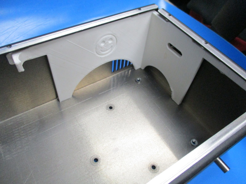
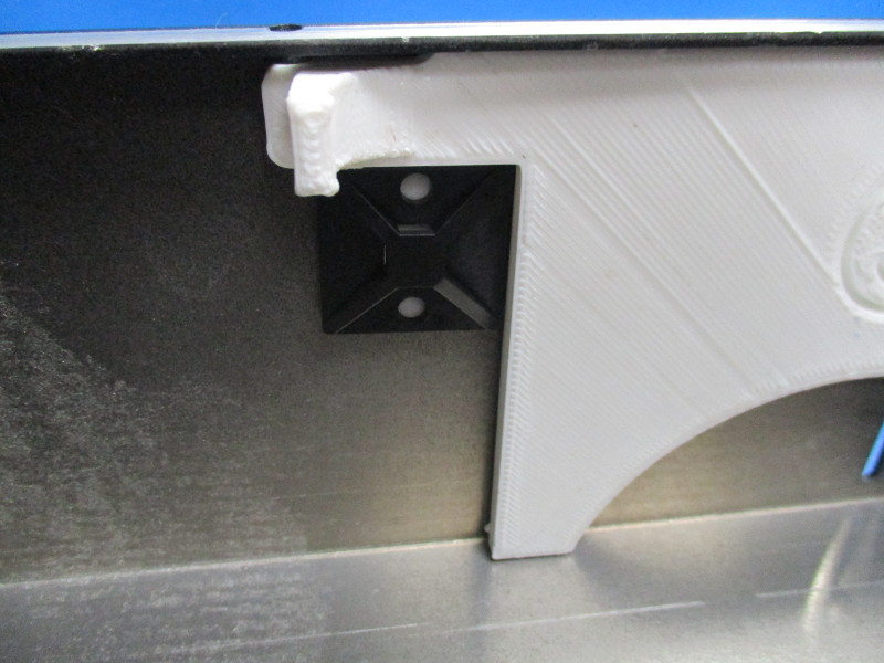
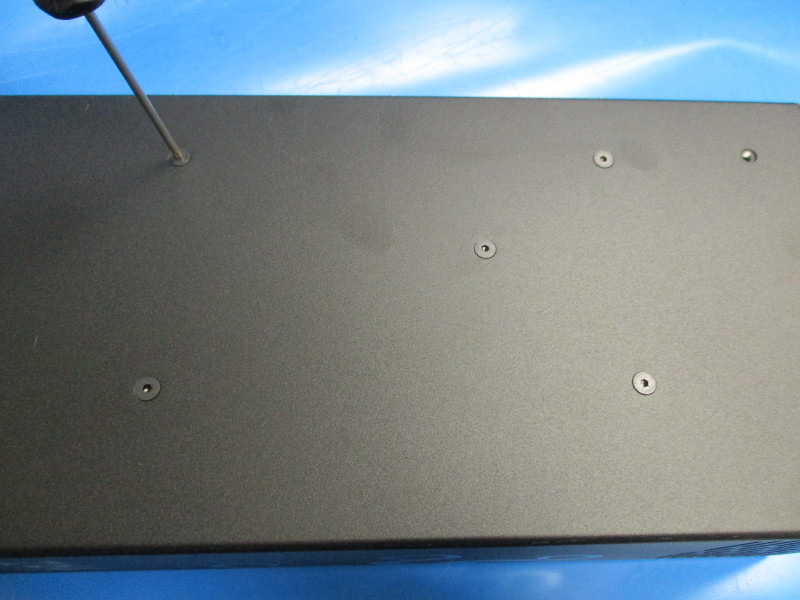
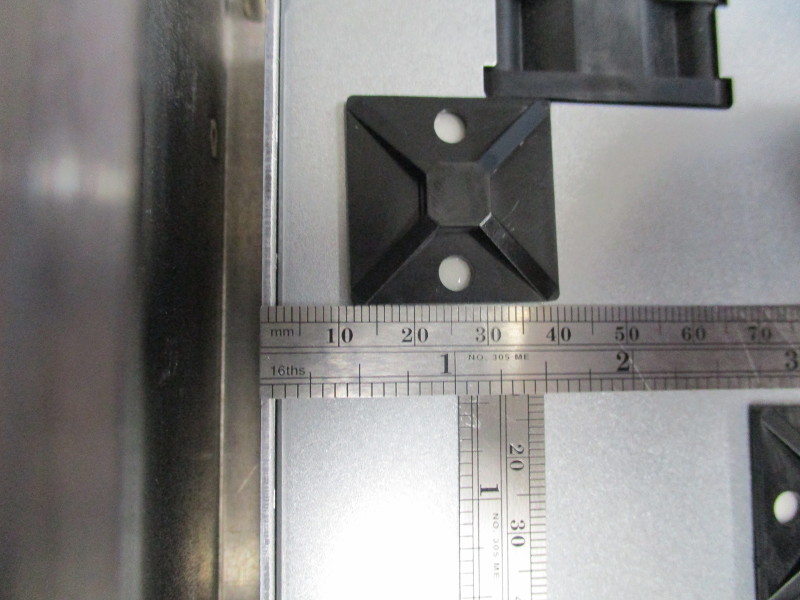
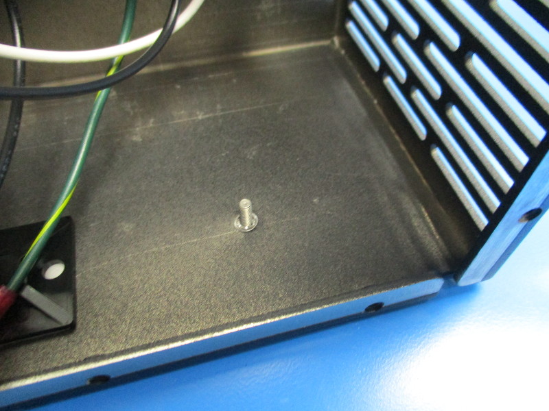
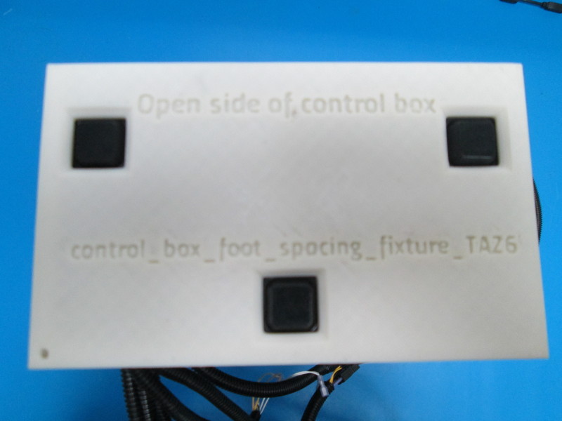
Install HD-MS0249 Tie holder adhesive square to the case using the white printed jig as shown.
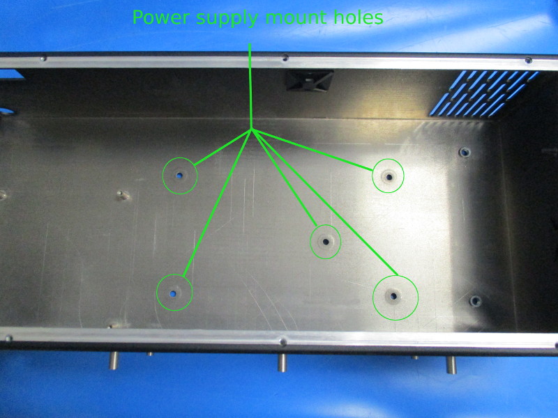
Install Power supply
Place the power supply in the case. Note orientation of the power supply. Align the power supply with the power supply mount holes. Secure the power supply using 5x- M4x6 FHCS. Torque to 5in*lbs
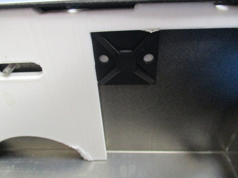
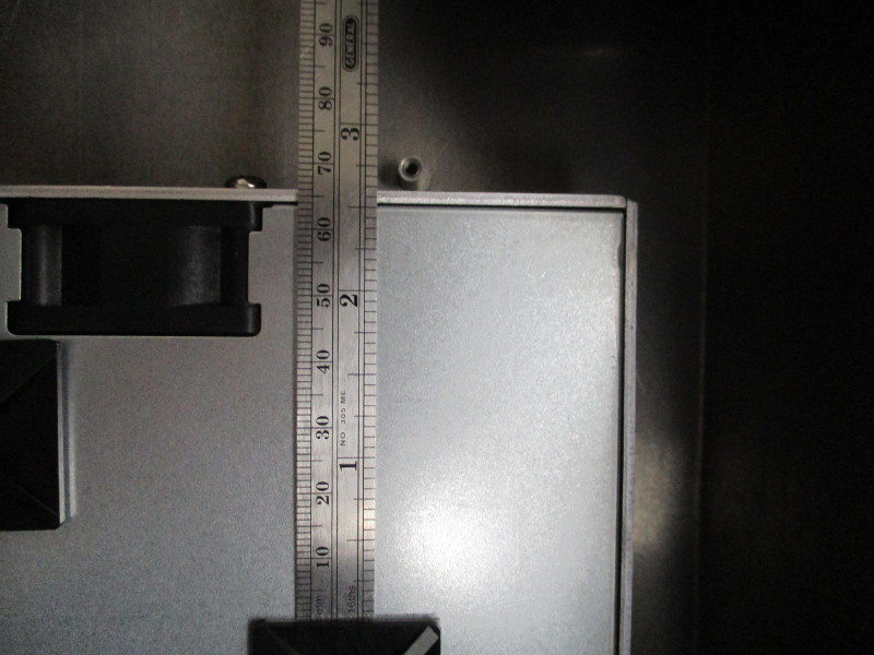
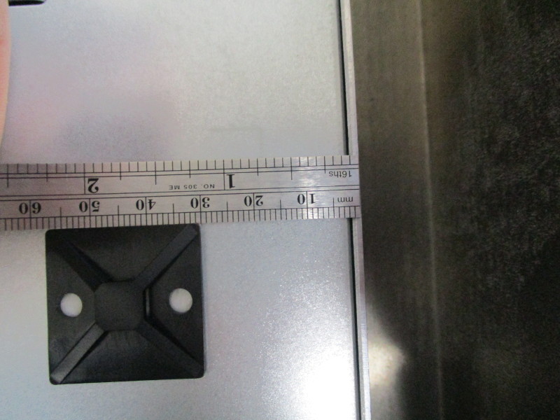
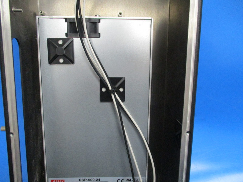
Install HD-MS0249 Tie holder adhesive square to the revealed face of the power supply.
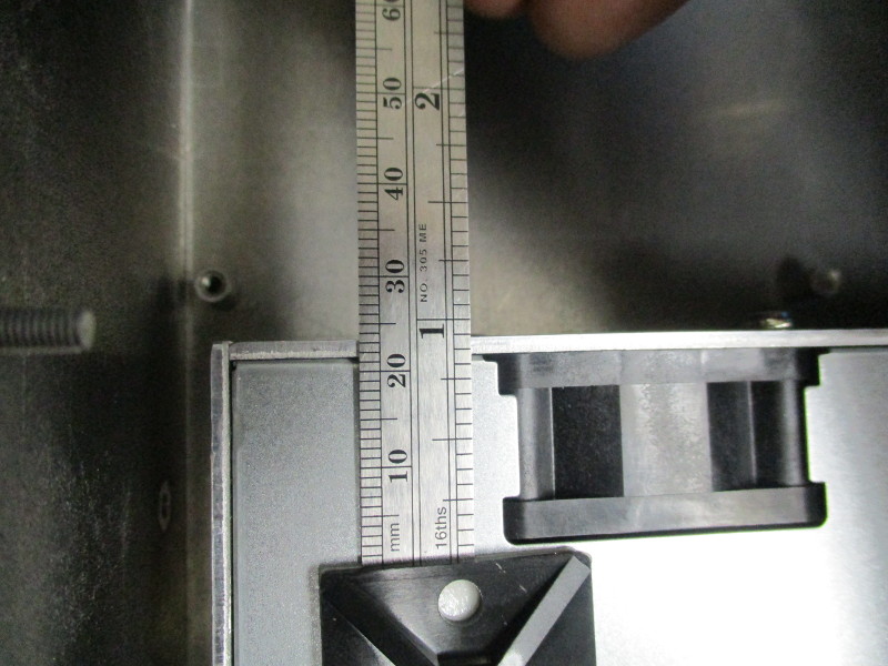
1x HD-MS0249 positioned approximately 23mm from the top in the left corner approximately 12mm from the left edge.
1x HD-MS0249 positioned 65mm from the top edge and 30mm from the right edge.
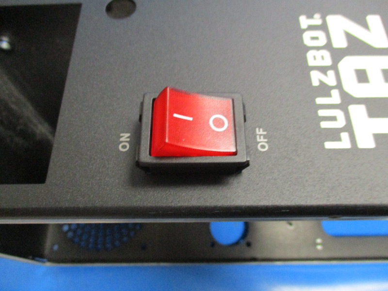
Install EL-SW0023 “Switch Rocker”
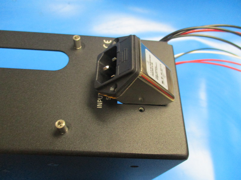
Install EL-MS0346 “Power Entry module”
The dual prongs need to be towards the bottom of the chassis. Secure with 2x M3x10 FHCS [HD-BT0116] at 5 inch-pounds
Connect EL-HR0077 “TAZ 6 CB to PS Black” and EL-HR0076 "CB Switch to PS White”.
EL-HR0077 Connects to the upper left terminal on the switch. EL-HR0076 connects to the upper right terminal on the switch.
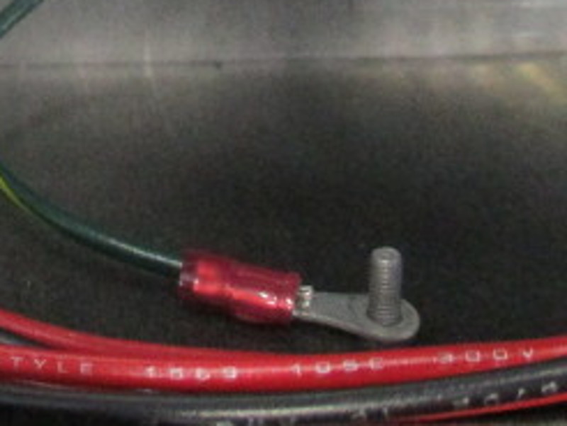
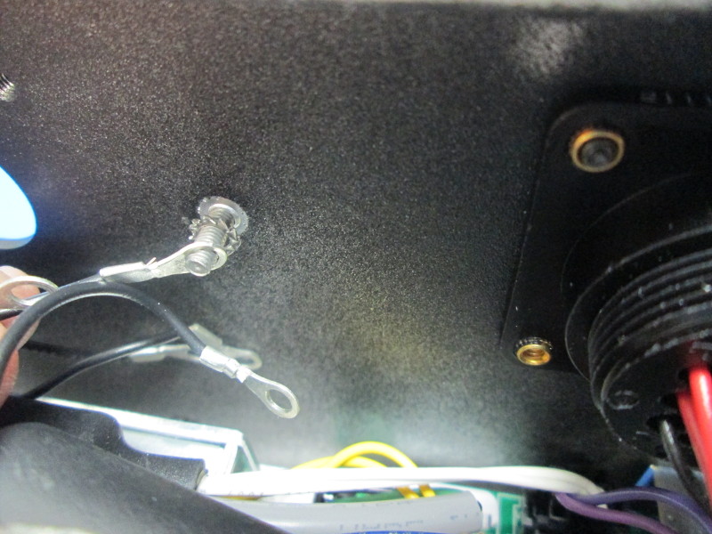
Connect EL-HR0079 “PS to GND” to the power entry ground post using a ground washer (HD-WA0027)
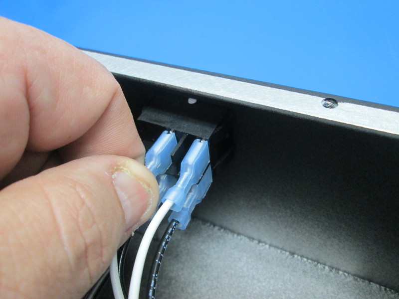
Connect EL-HR0080 “CB Plug to Switch Harness”, with the ferrite closest to the power entry module, into the power entry module. White wire on the left upper terminal, black wire on the right lower terminal. Connect opposite ends of the harnesses to the power switch, White wire on the right terminal and the black wire on the left terminal.
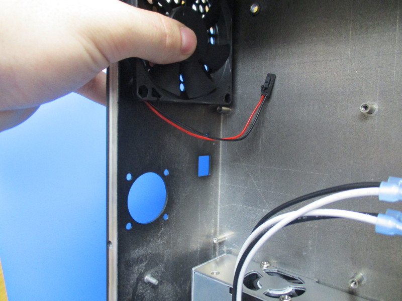
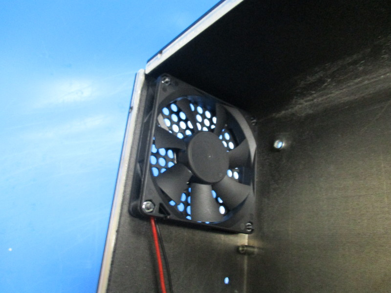
Install fan (EL-FA0036) with the fan label facing toward the inner wall of the control box, wiring exiting the fan away from the case top. Use 4x M3x20, 4x M3 washers and 4x M3 nuts to secure the fan to the case. Hand tighten.
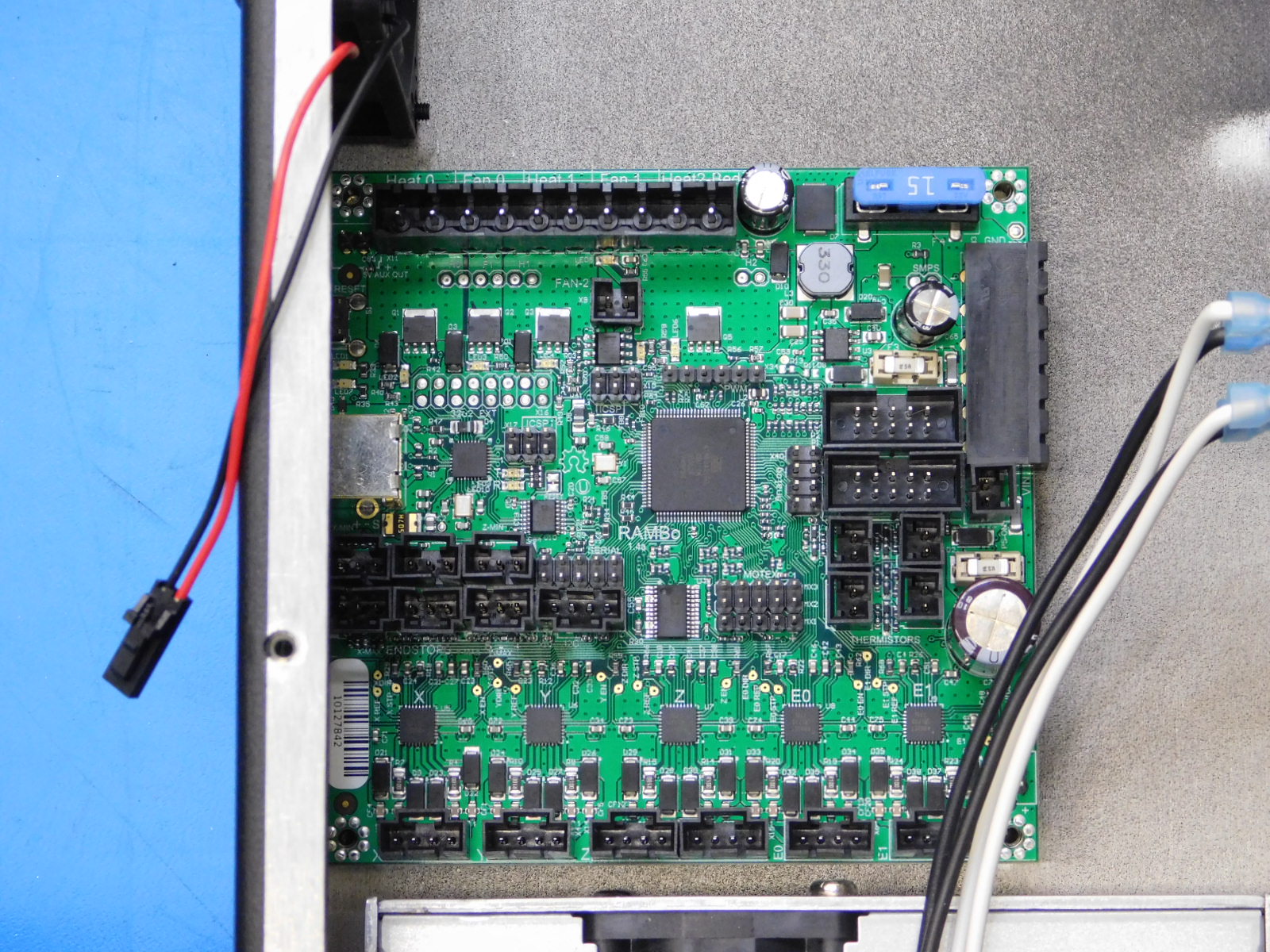
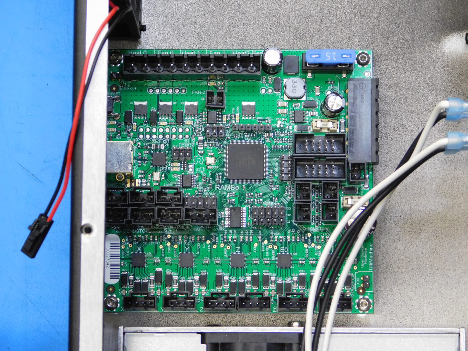
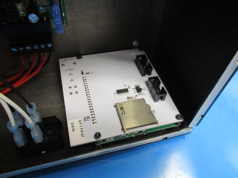
Align RAMBo with the mounting standoffs located above the power supply. Align the USBB port on the RAMBo with the cut out on the case. Secure with 4x M3x8 SS BHCS. Torque to 5in*lbs
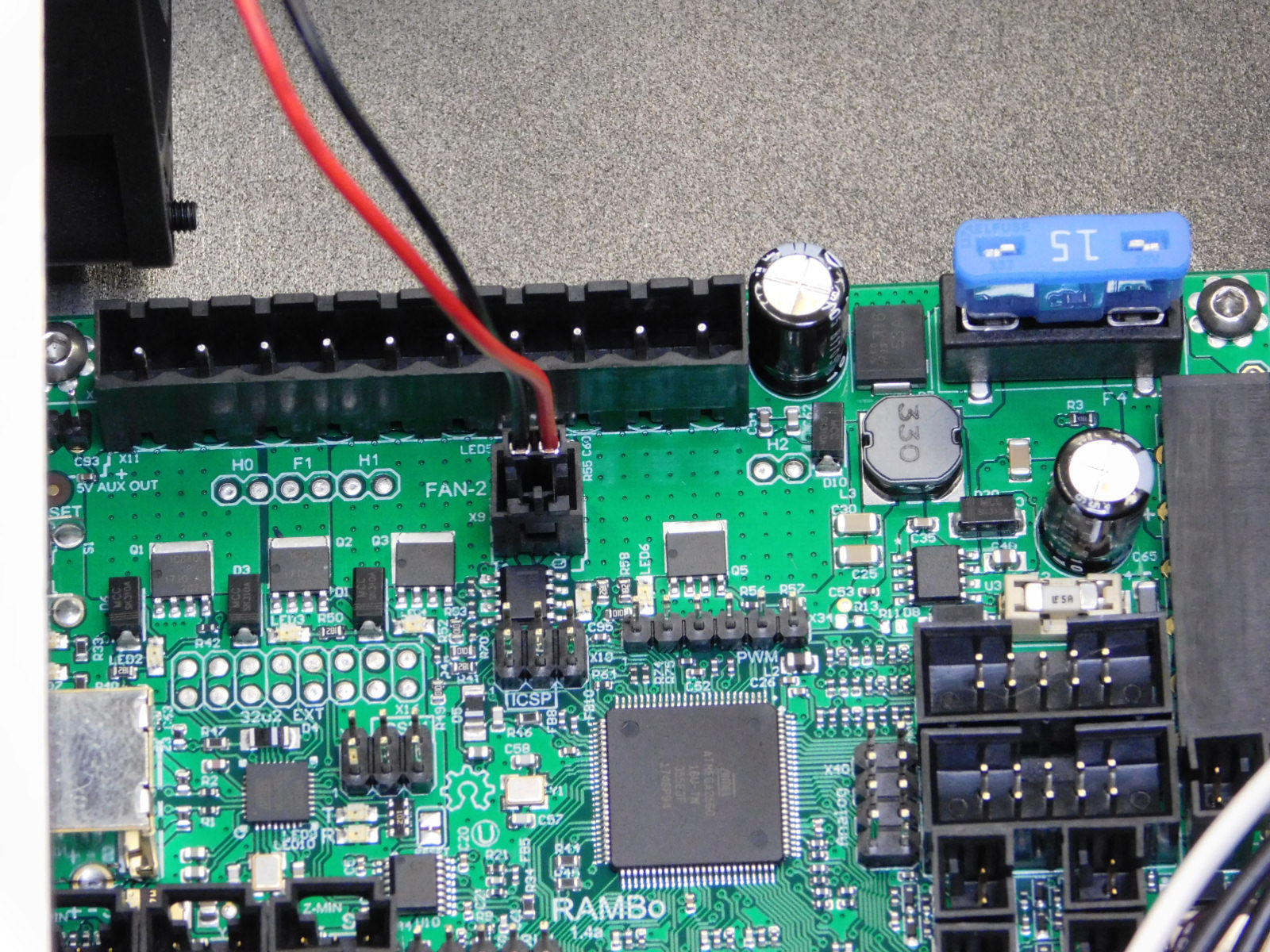
Plug fan into RAMBo
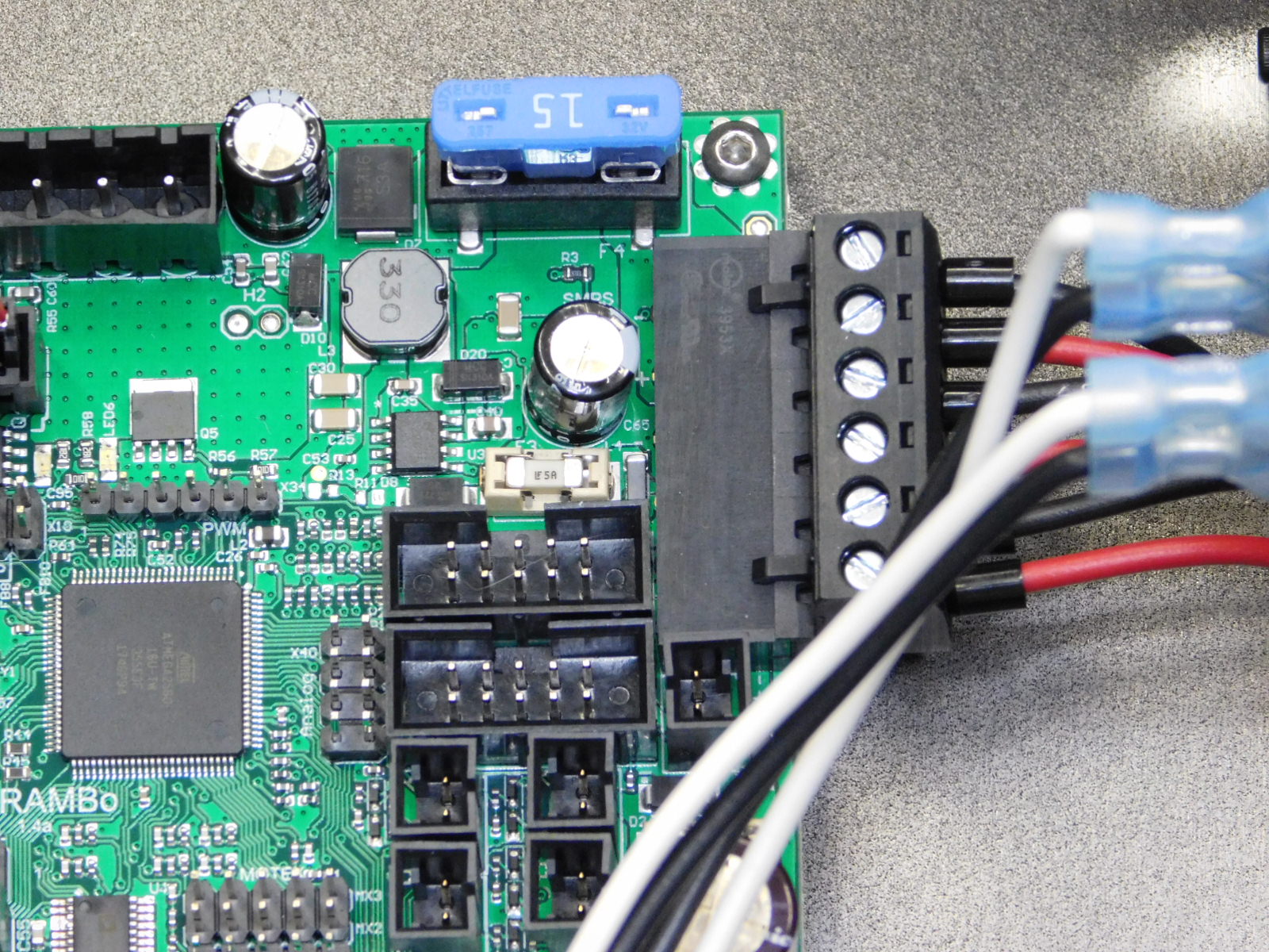
Connect CB DC power to RAMBo
Zip tie EL-HR0074 “CB DC Power” to both tie downs that were installed on the case walls.
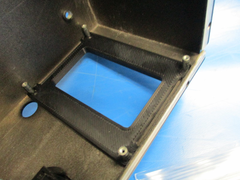
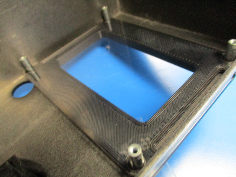
Install LCD bezel against the case, then the LCD screen protector against the LCD bezel
Remove LCD clear protective plastic
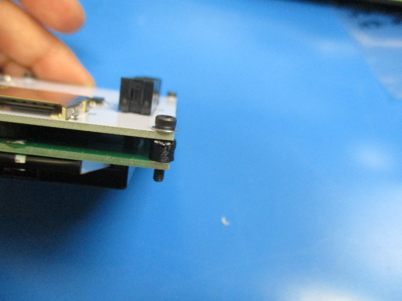
Install printed LCD spacers into LCD assembly screw mount hole locations (4x);
Install 4x- M2.5x12 SHCS and 4x- M2.5 washers into the four mount holes in the corners of the LCD PCBA
Align LCD with mounting standoffs- install screws to 3in*lbs
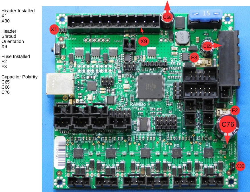
THESE STEPS MUST BE COMPLETED IN THE DEFINED SEQUENCE FOR FCC APPROVALS
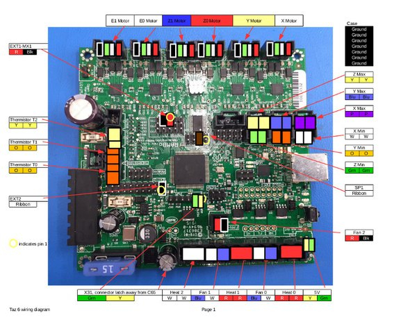
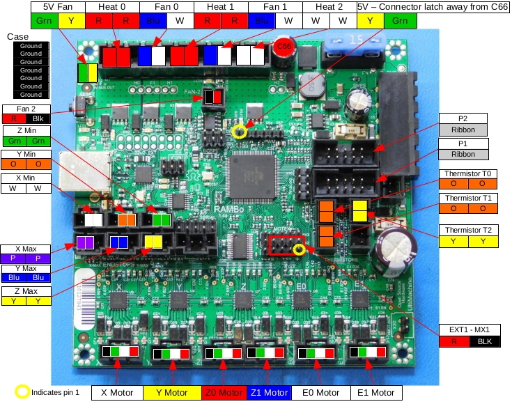
For steps requiring connection to the RAMBo refer to the TAZ 6 Wiring connection document
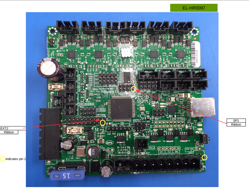
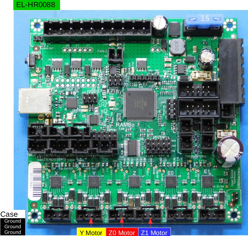
Plug in EL-HR0088 CB Y-Z Harness into RAMBo then pass its 16 position connector through to the interconnect housing transition
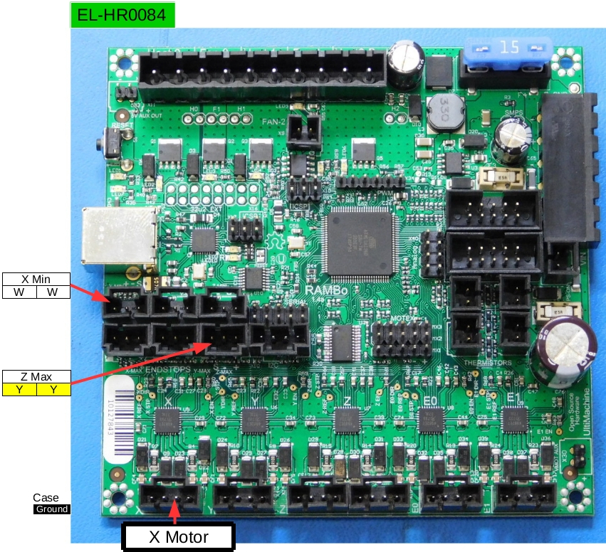
Plug in EL-HR0084 CB X Harness into RAMBo then pass its 12 position connector through to the interconnect housing transition
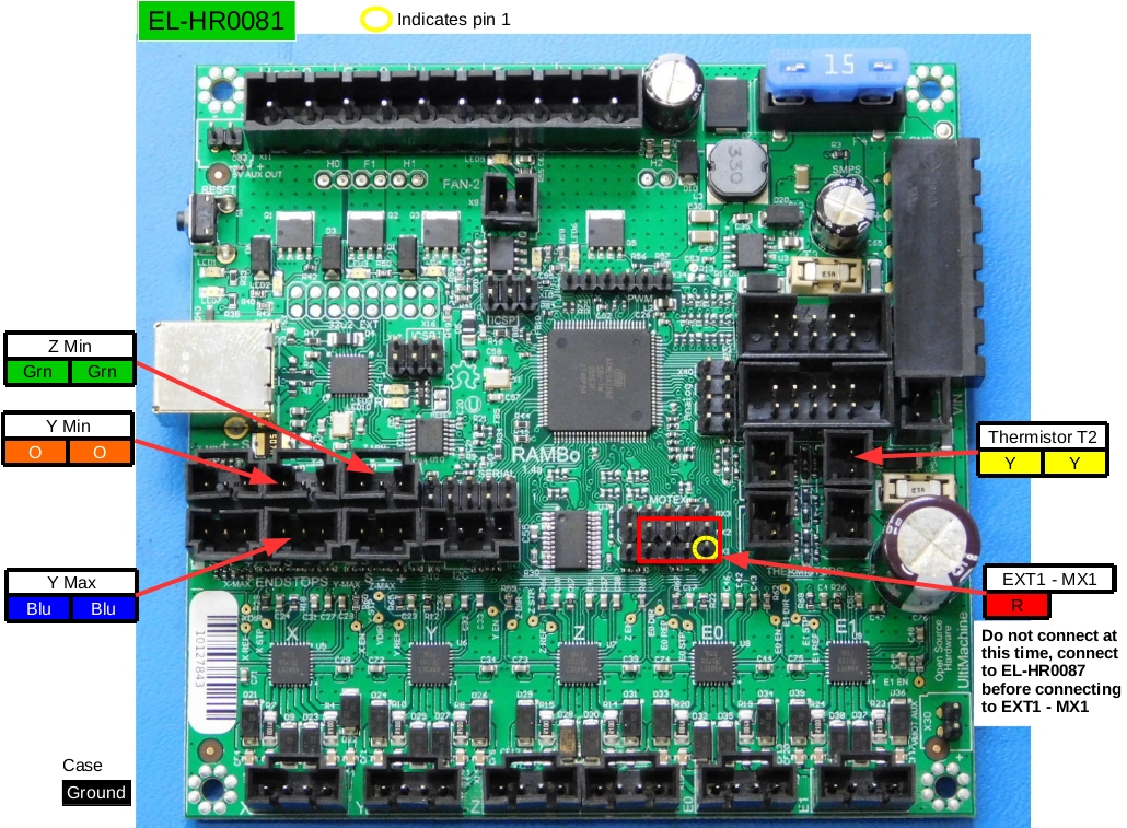
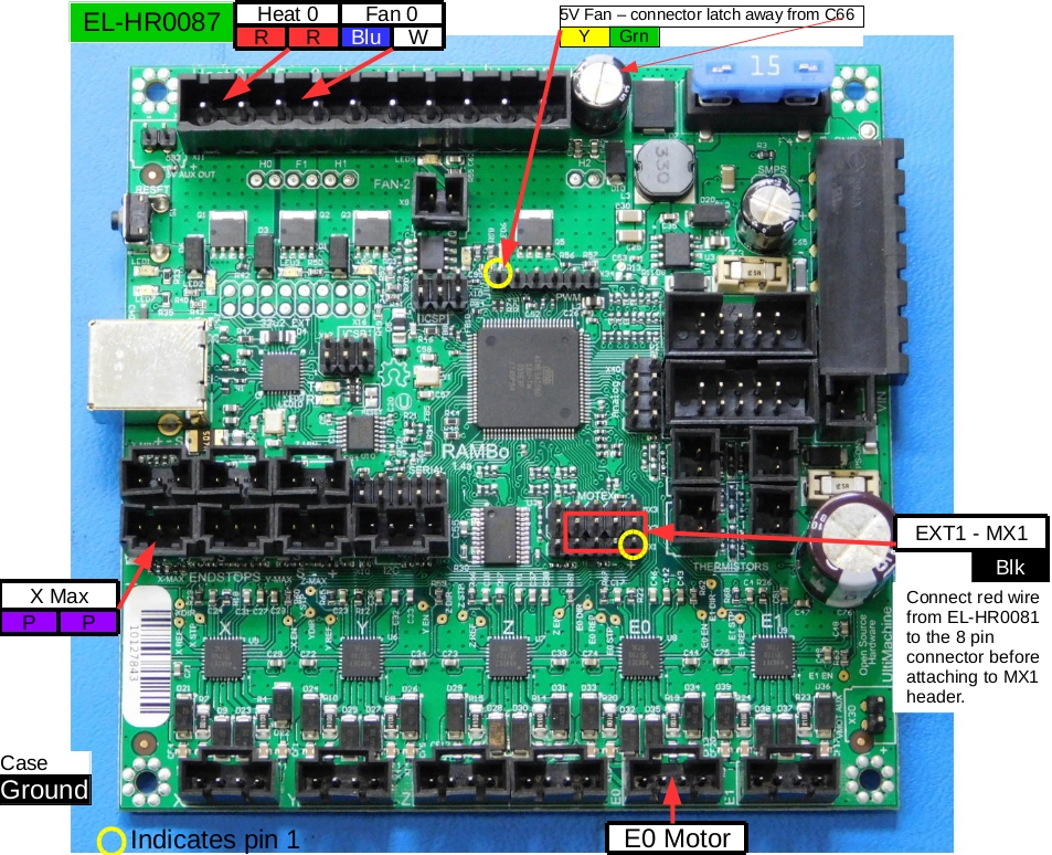
Plug in EL-HR0081 CB Bed Harness into RAMBo then pass its 10 position connector through to the interconnect housing transition- a single red wire without connector will remain unconnected until a later step
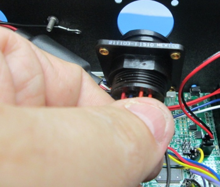
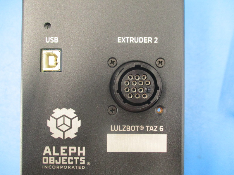
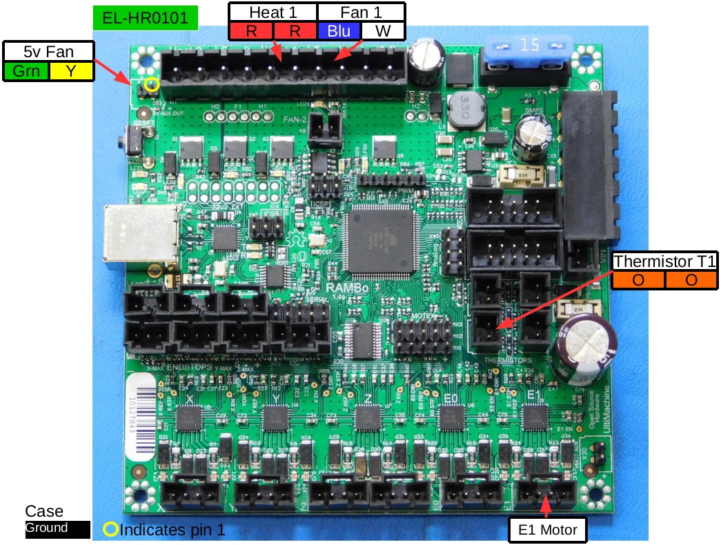
Install the Dual Extruder harness (EL-HR0101) from the inside the case, set the orientation of the connector so socket #5 (empty socket) of the connector is away from the USB connector; secure the connector with 3x- 18-8 FHS Black Oxide; tighten to 3in*lbs; Connect the cable to the RAMBo
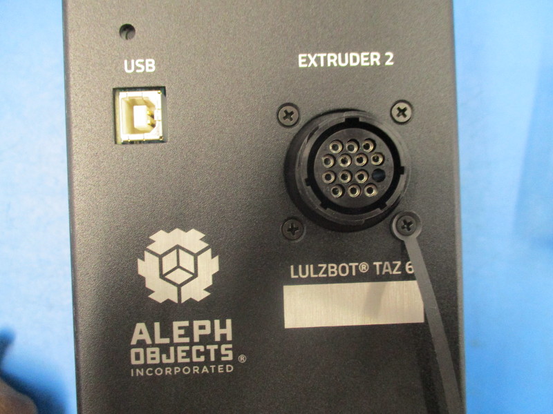
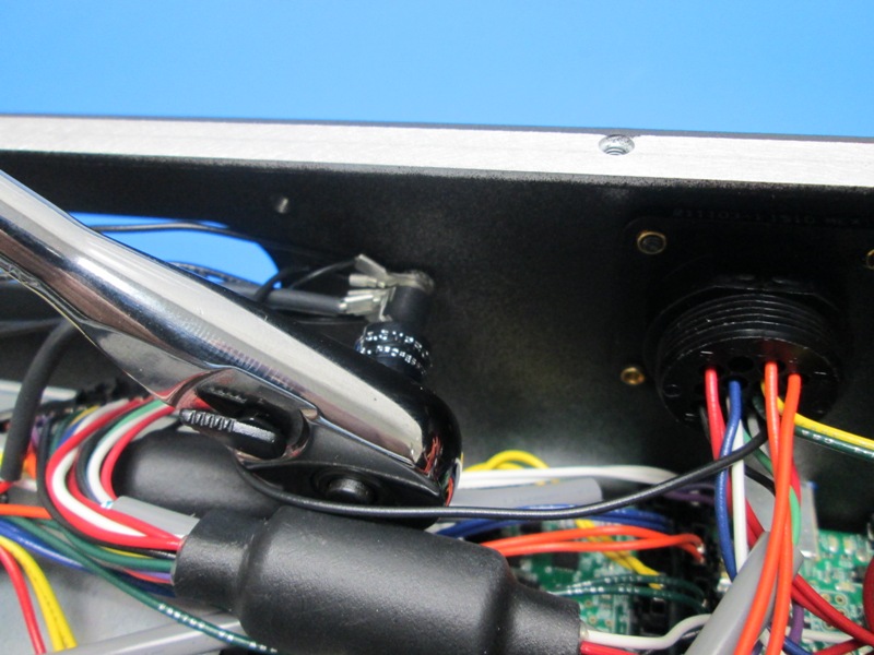
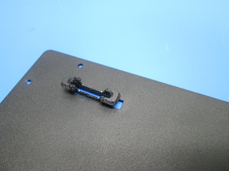
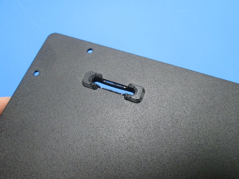
Position the EL-MS0144 (Sealing Cap) strap so the strap will double over itself when the cap is installed onto the 16position round connector, secure the sealing cap with 1x- 18-8 FHS Black Oxide; tighten to finger tight, the cord should not be able to rotate once tightened. Cover the connector with the sealing cap.
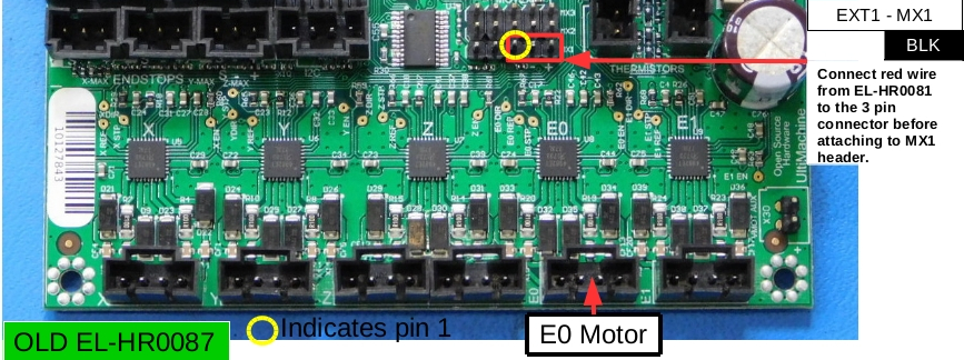
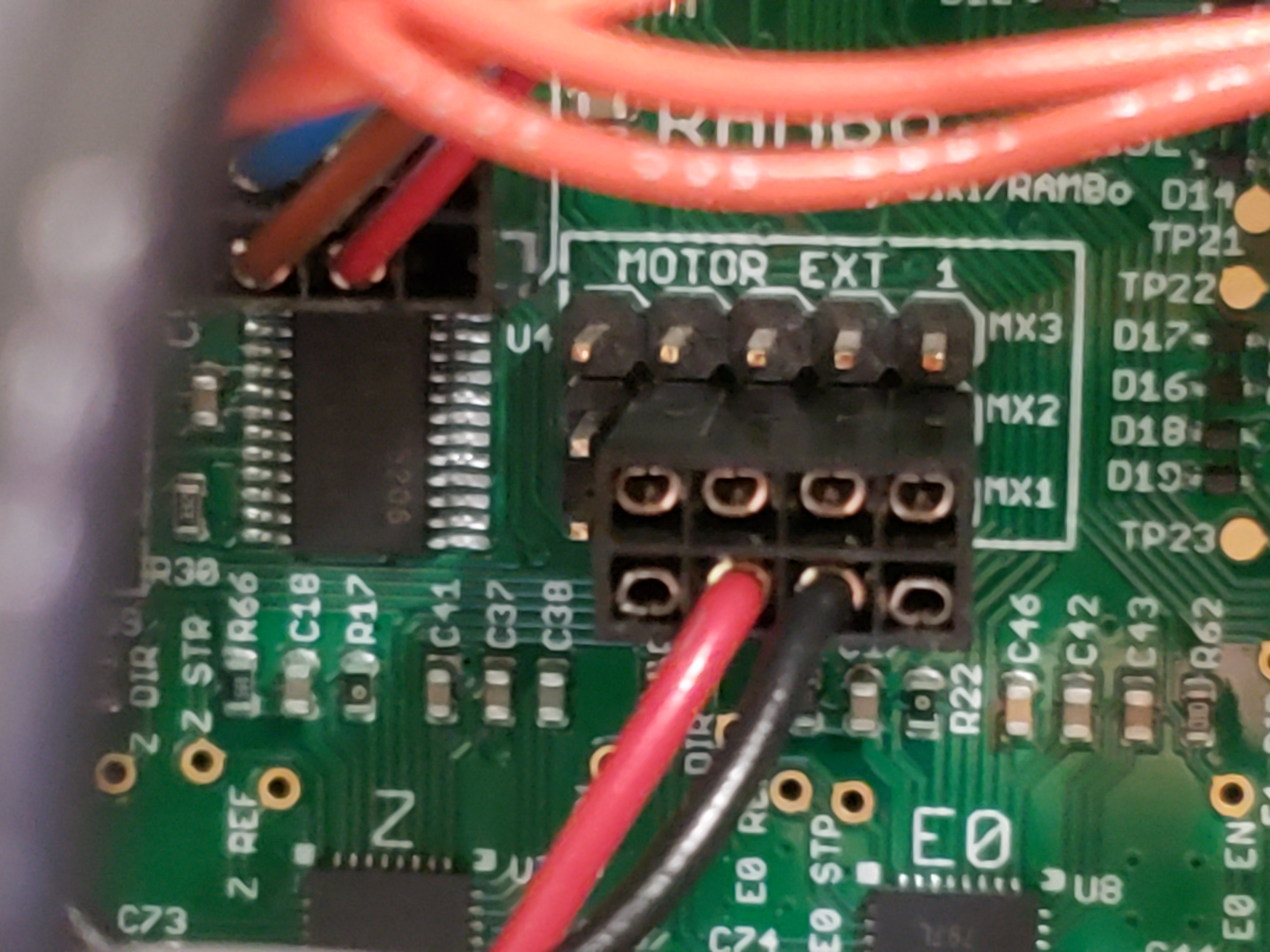
Plug in ELHR0087 CB Extruder Harness into RAMBo then pass its 20 position connector through the interconnect housing transition- Connect the single black wire with connector to the single red wire from EL-HR0081, insert red wire into connector position 1 which is marked MX
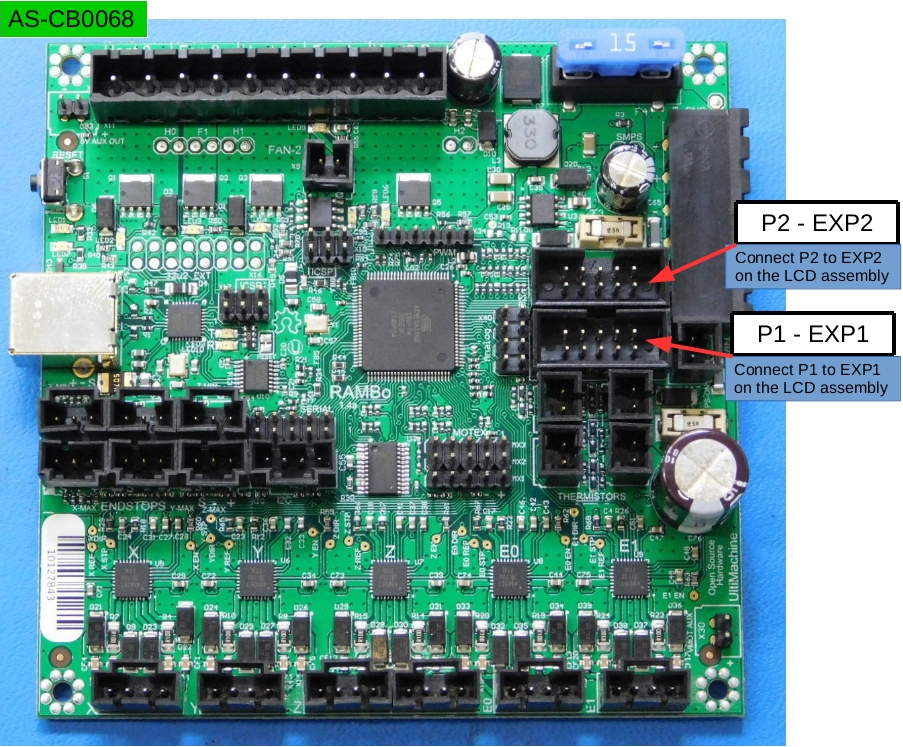
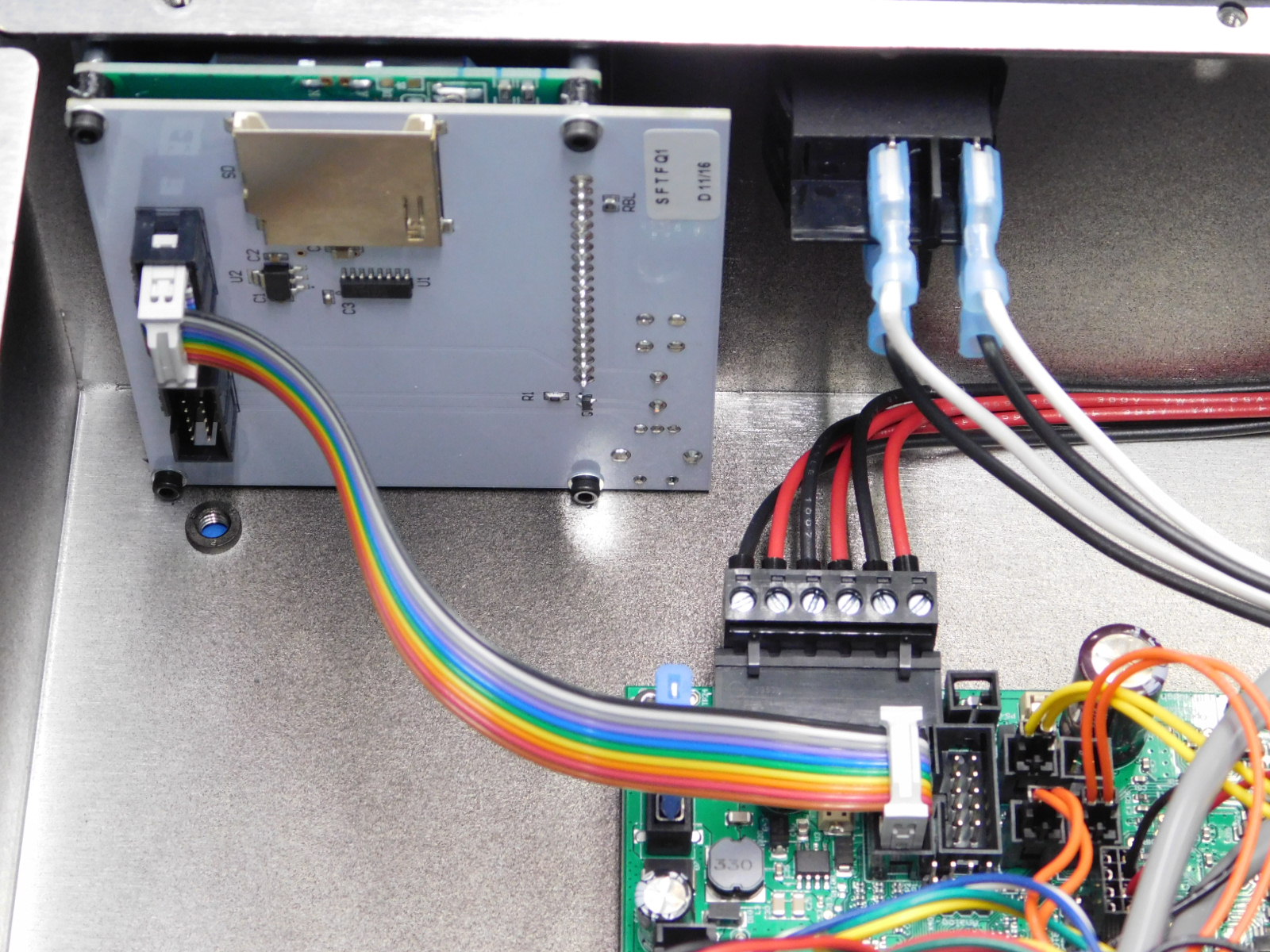
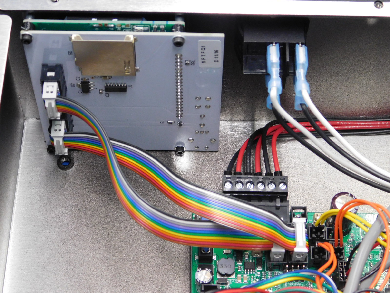
Plug in 2x AS-CB0068 CB LCD Harness v2 to the RAMBo and LCD; Connect LCD EXP1 to RAMBo P1; connect LCD EXP2 to RAMBo P2
Plug in Case fan to RAMBo FAN2 location
Plug in EL-HR0082 CB Bed Power Harness to the RAMBo then pass the 2 position connector through to the interconnect housing transition
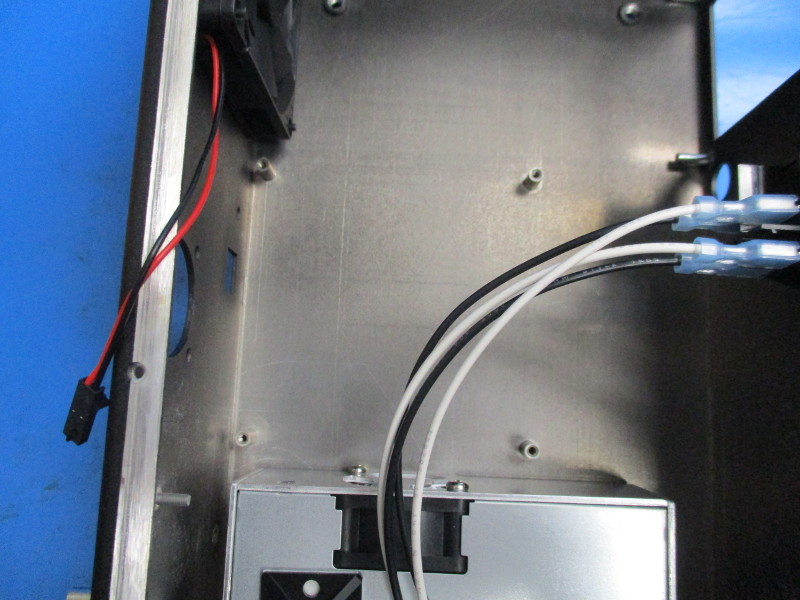
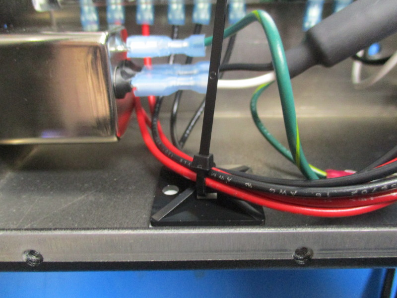
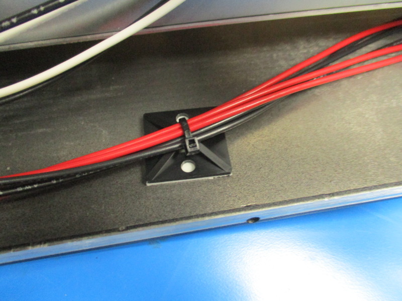
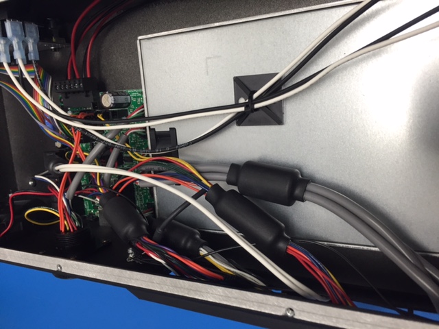
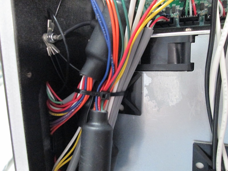
Route Red and Black Power Supply wires to second tie down, ensure sufficient service loop and bend radius is maintained (see picture), secure wire with Ty Wrap with the securing latch positioned toward the case opening
Install 1x- M3 star washer to the case ground lug near the RAMBo, install 7 ground wires from the internal cable harness to the ground lug, secure with 1x- M3 Nyloc nut tightened to hand tight (if using a ratchet beware of over-tightening the nut)
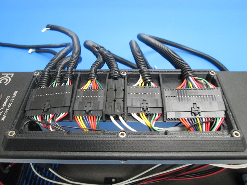
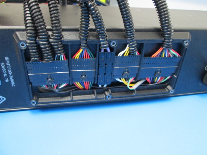
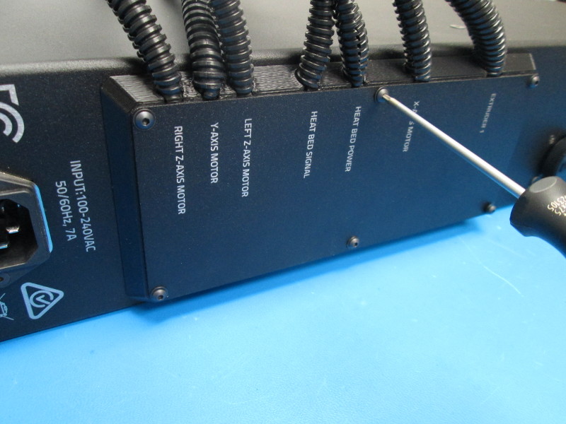
Install Interconnect Housing on case exterior, verify slot in interconnect Housing aligns with slot in case
Route connectors from each of the internal harnesses into the Interconnect Housing, connectors sizes indicate proper position in the Interconnect Housing
Connect external cables to each of the internal connectors:
Internal Harness (# of connector positions) and mating External harnesses
EL-HR0088 CB Y-Z Harness (16) to EL-HR0091 Y-Z Harness (16)
EL-HR0084 CB X Harness (12) to EL-HR0075 X Harness (12)
EL-HR0087 CB Extruder Harness (20) to EL-HR0092 Extruder Harness (20)
EL-HR0081 CB Bed Harness (10) to EL-HR0083 Bed Power Harness (10 & 2)
EL-HR0082 CB Bed Power Harness (2) to EL-HR0083 Bed Power Harness (10 & 2)
Secure Panduit in Interconnect Housing for 10- 15 mm of Panduit to extend from Interconnect Housing front into the housing; Panduit must be pushed down into the interconnect housing retention slot; wires must be inside the conduit so they are safe from damage when the interconnect cover is installed
Install interconnect housing cover with 6x- M3x12 BHCS and 6x- M3 washer; tighten to hand tight; ensure the cover is flush to the interconnect housing and the interconnect housing is flush to the case. DO NOT TIGHTEN screws past hand tight to force either the cover or the interconnect housing into place.
Inspect wiring layout to ensure all connections are made and wires are laying correctly
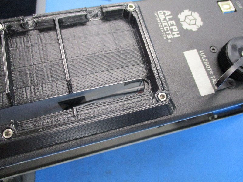
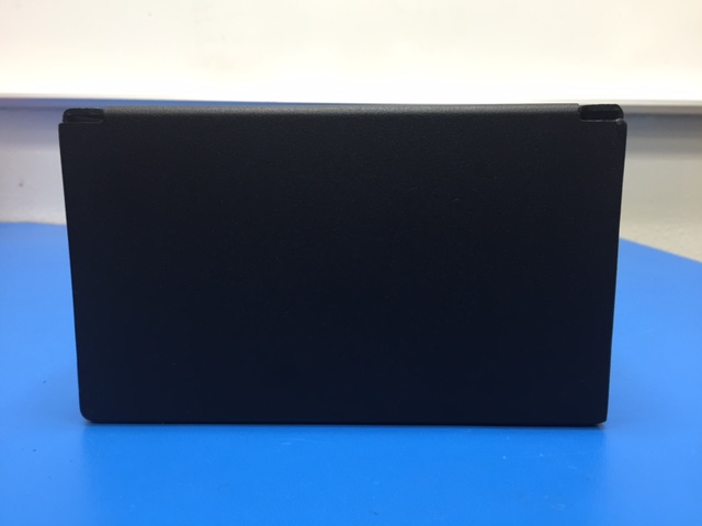
Install SD card Bezel into the case cover (entry direction is from the painted side of the cover); install cover onto case with the SD card slot aligned with the SD card reader
Secure the case cover with 14x- M3x8 BHCS and 14x- M3 washers; tighten to 5in*lbs
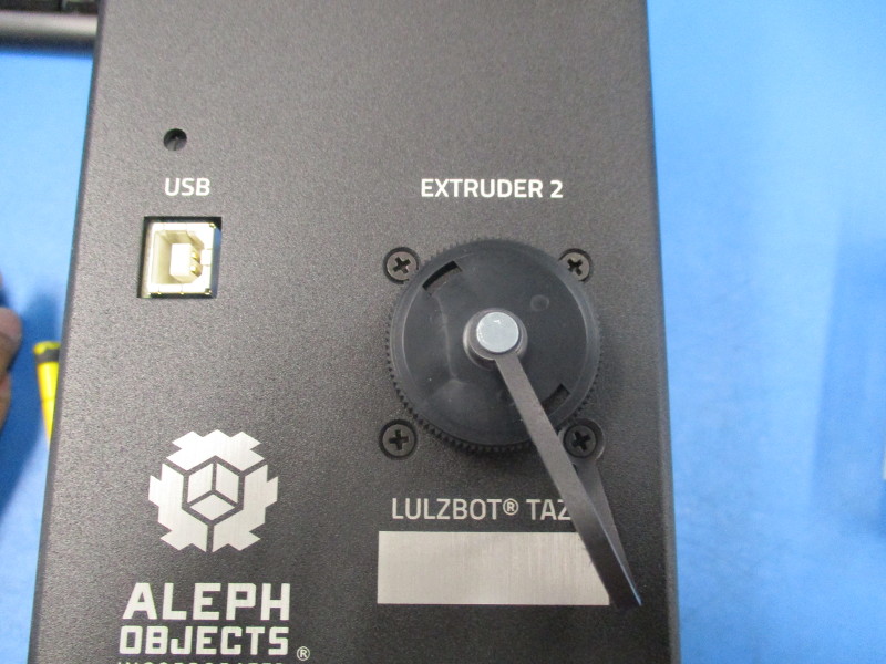
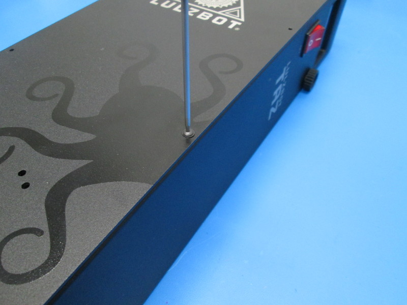
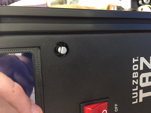
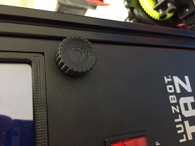
Install Flexy LCD Knob
Wipe down the bottom of the case with Alcohol; remove three (3) 3/4” square, 1/4” high bumpers from their protective backing apply the bumpers to the case
Install LulzBot test firmware; test unit to ensure all motors (6) correctly rotate, all fans (3) correctly rotate, all switches (7) properly operate, and the LCD display properly lights up, makes sounds as the LCD menu is navigated, and the control Knob functions.
Refer to the diagrams for instructions for connecting the Rambo 1.3L that was in use prior to 1.4a.