Open HardwareAssembly Instructions
Guides for installation and assembly of the LulzBot line of products made by FAME 3D LLC.
Guides for installation and assembly of the LulzBot line of products made by FAME 3D LLC.
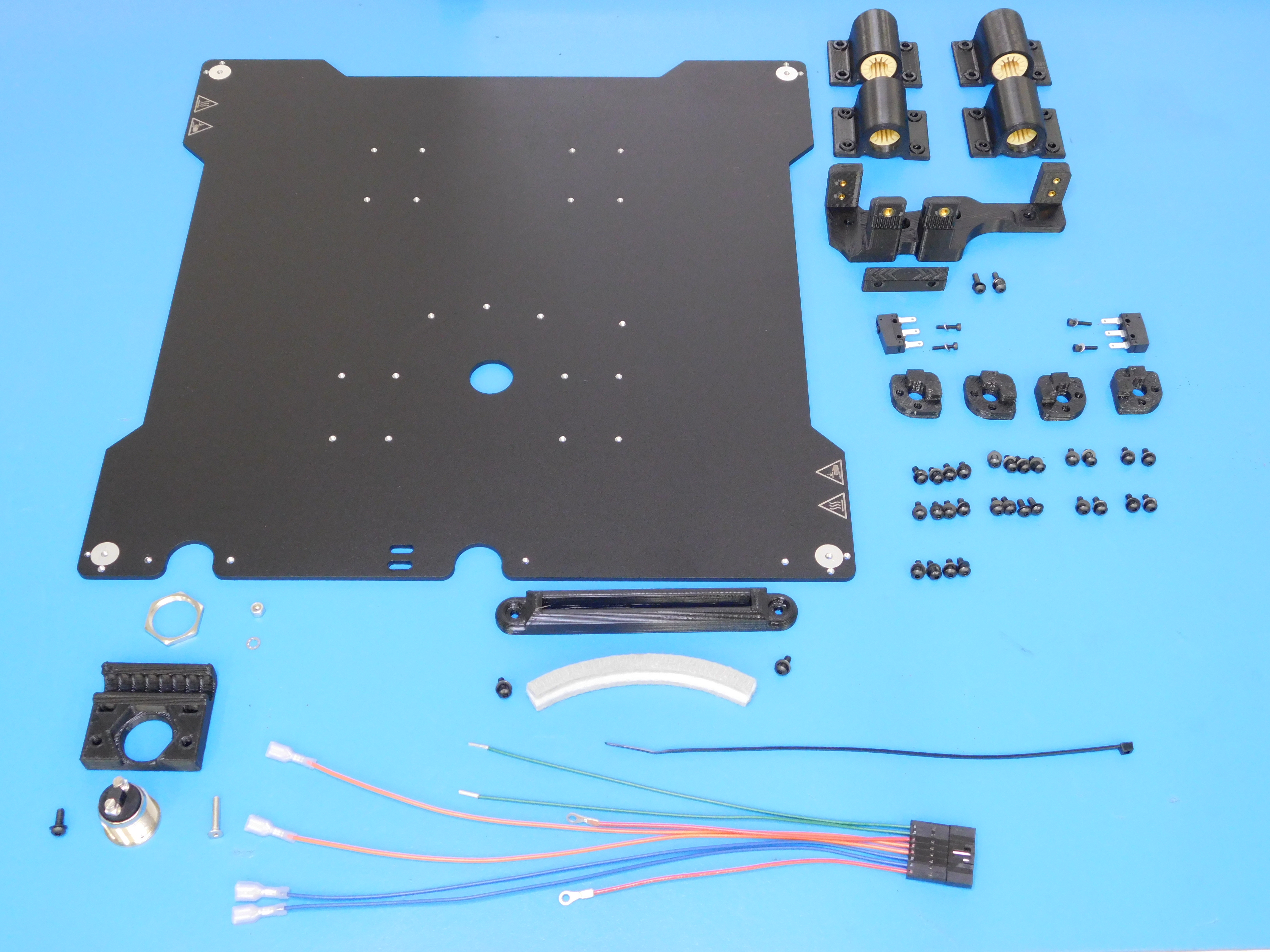
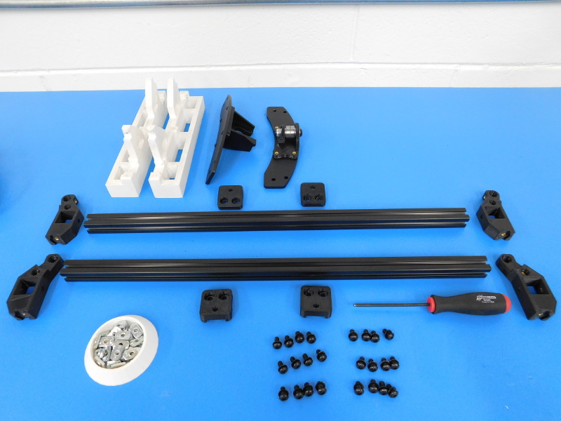
Parts:
1x- Z switch mount (PP-GP0216)
1x- Y-Belt Mount (AS-PR0024)
1x- Y-Belt Clamp (PP-GP0304)
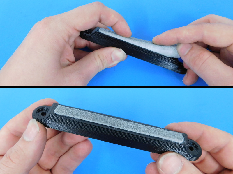
1x- Wiper Mount (PP-GP0231)
1x- Wiper pad (AS-PR0023)
4x- 10mm Single Bearing Holder (with Bearings) [AS-PR0025]
4x- Bed corners (PP-GP0221)
1x- Y belt mount (AS-PR0024)
1x- Bed plate (PP-FP0080)
1x- Momentary switch (EL-SW0030)
2x- SPDT switches (EL-SW0022)
1x- M3x16 Stainless FHCS (HD-BT0082)
30x- M3x8 BHCS (HD-BT0137)
4x- M2x10 SHCS (HD-BT0107)
1x- M3x10 BHCS (HD-BT0148)
31x- M3 black washers (HD-WA0038)
4x- M2 washers (HD-WA0012)
1x- TAZ 6 Bed Harness Extension (EL-HR0089)
1x- M3 Nyloc Nut (HD-NT0001)
1x- Internal Tooth Lock Washer (HD-WA0027)
Tools:
5.5mm Nut driver
1.5 mm Hex driver
2.0mm Hex driver
Standard Screw Driver (small blade)
Flush Cutters
Instructions
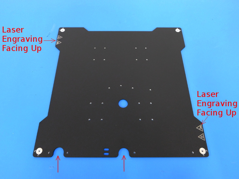
Carefully place a Bed Plate (PP-FP0080) on your workbench, with the notches facing towards you and the laser engraved side facing up.
Loosely attach the bed corner with two (2) M3X8 BHCS and two (2) M3 Black washers to each of the four (4) bed corners to the plate. These will be tightened later when the bed is attached.
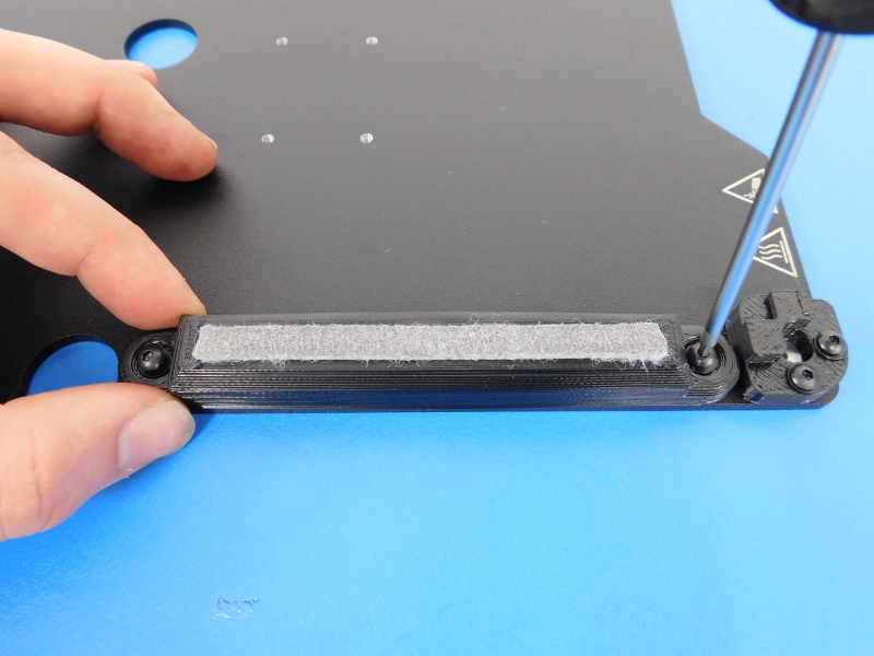
Using two (2) M3X8 BHCS with two (2) M3 Black washers loosely attach the wiper mount to the plate as shown. These will be tightened later when the bed is installed.
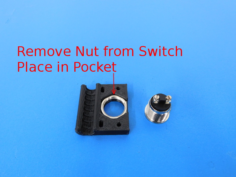
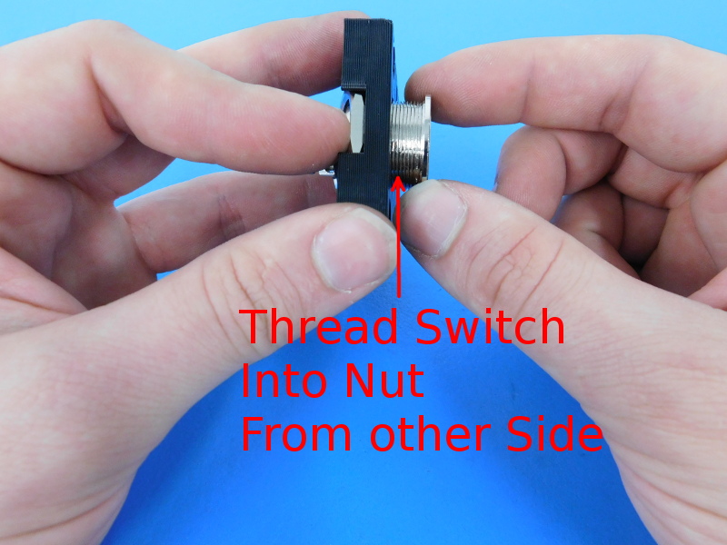
Install the Momentary Switch (EL-SW0030) into the Z-min Switch Mount (PP-GP0216) by first removing the retention nut from the switch and laying it inside the hexagonal shaped pocket on the underside of the Z-Min Switch Mount.
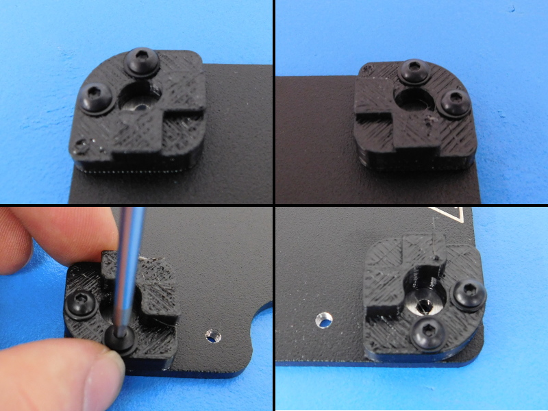
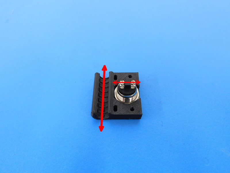
Tighten the switch onto the mount so that the terminals are perpendicular to the cable pathway, as pictured. You may need to loosen the retention nut to reposition in in the mount.
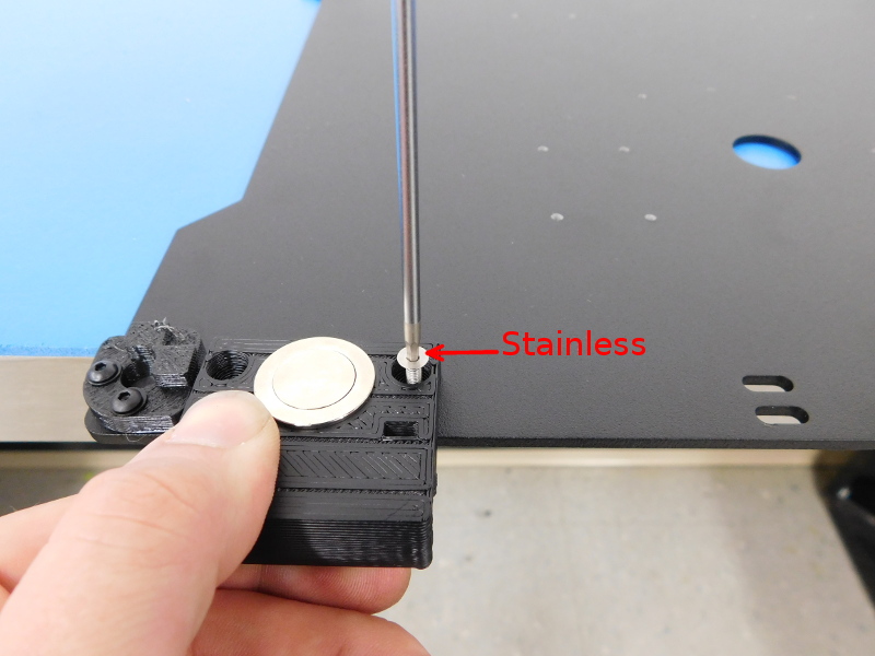
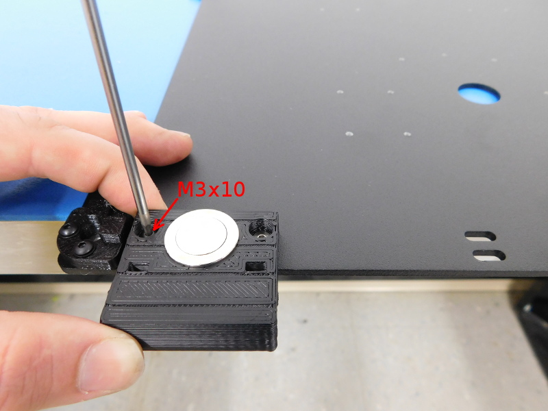
Secure the Z-Min Switch Mount to Bed Plate, using one (1) stainless M3X16 FHCS (HD-BT0082) towards the inside of the plate, one (1) M3X10 BHCS (HD-BT0148) and one (1) M3 Black Washer (HD-WA0038) on the other side.
Flip the plate over;
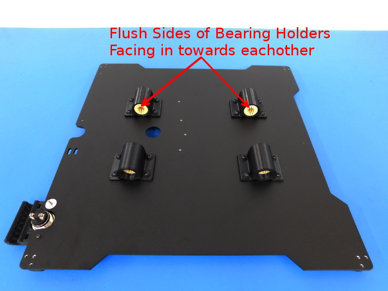
Loosely secure the 10mm Bearing Holders [AS-PR0025] to the bottom of the Bed Plate using sixteen (16) M3X8 BHCS (HD-BT0137) and sixteen (16) M3 Black Washers (HD-WA0038). Make sure to orient them as pictured, with the flush sides of the bearing holders facing towards each other.
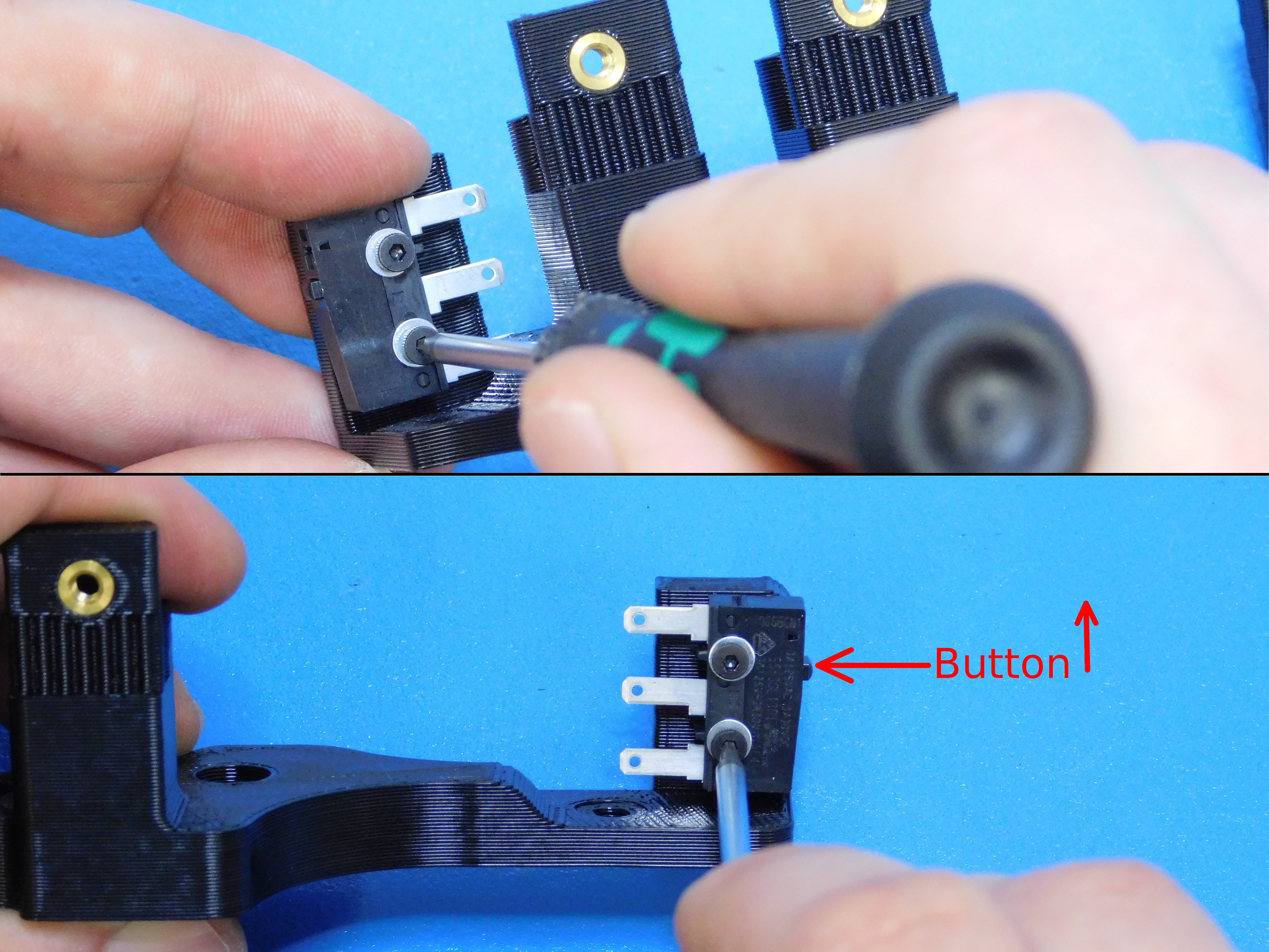
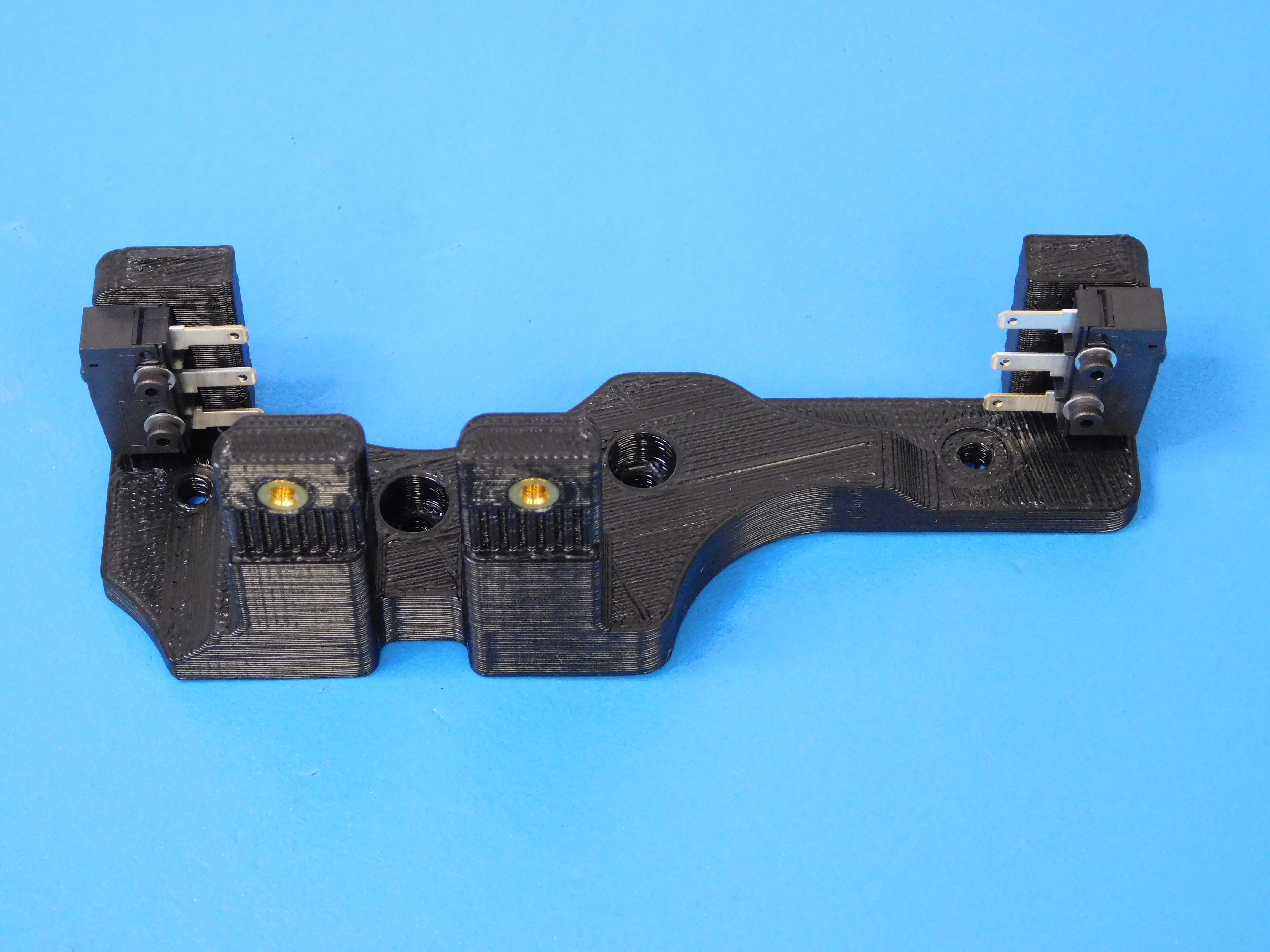
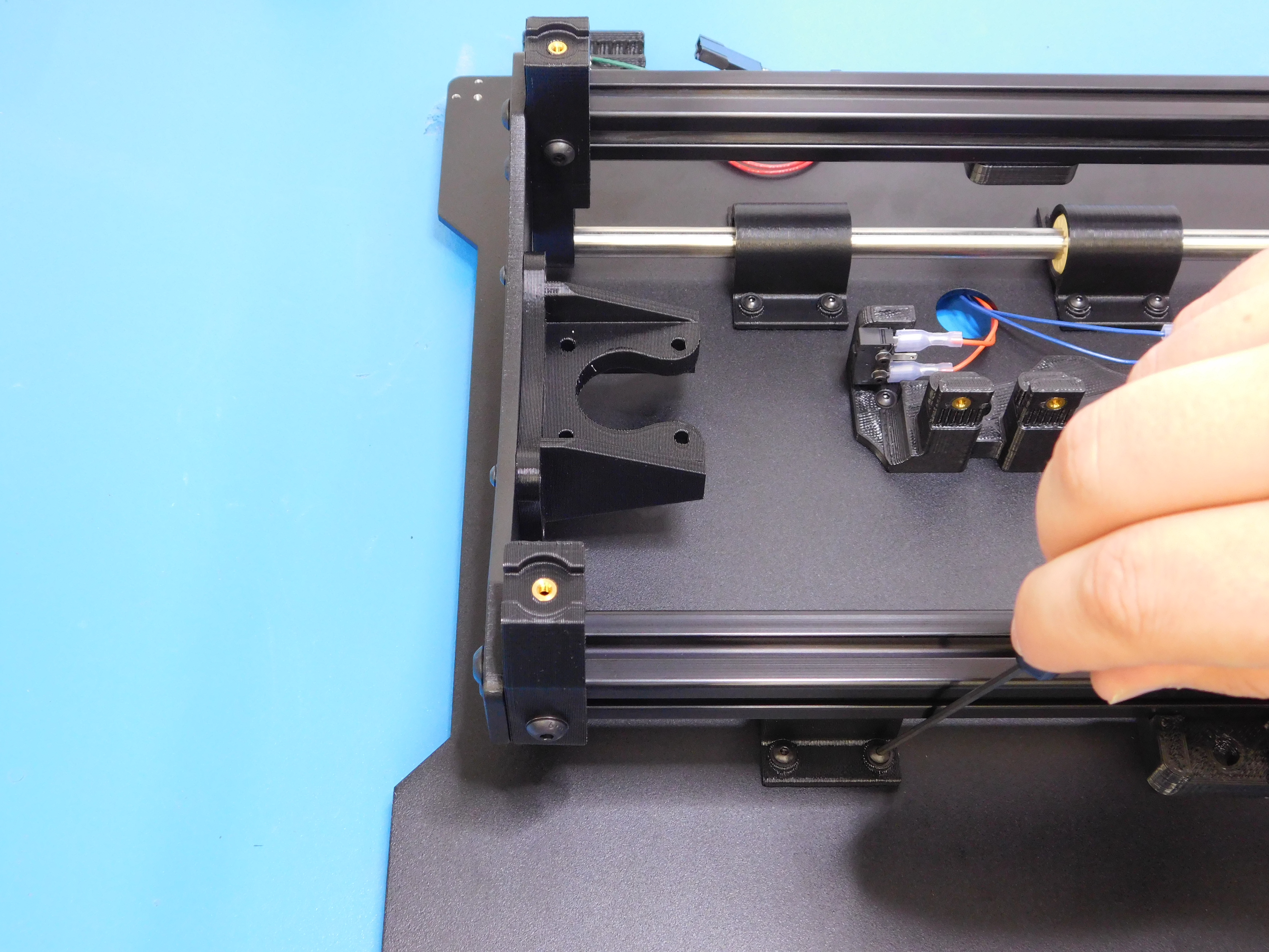
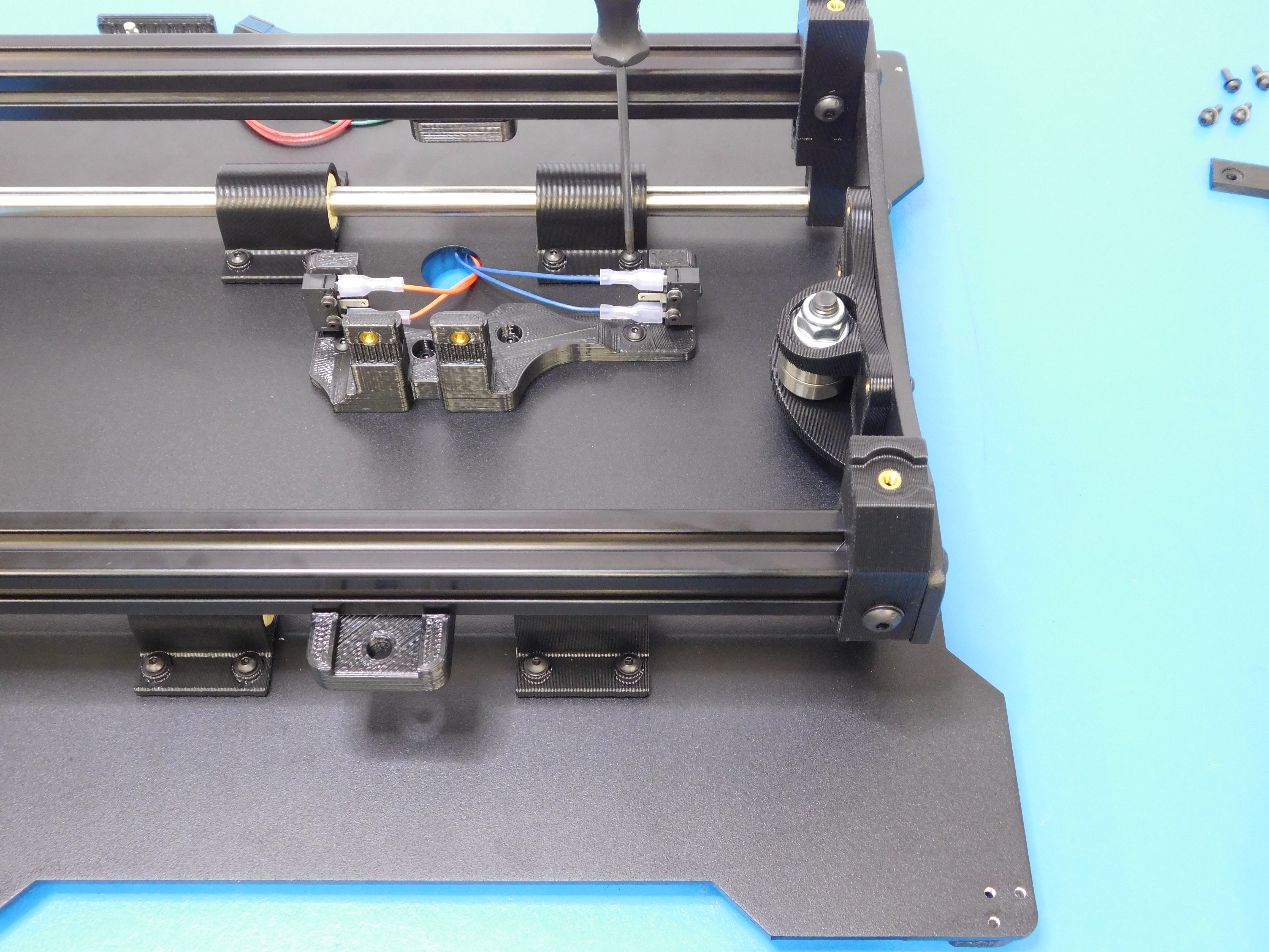
Install two (2) SPDT Switches (EL-SW0022) to the Belt Mount (AS-PR0024) using two (2) M2x10 SHCS (HD-BT0107) and two (2) M2 washers (HD-WA0012) onto each end of the Y belt mount with wiring terminals facing each other and the switch actuator away from the plate, as pictured.
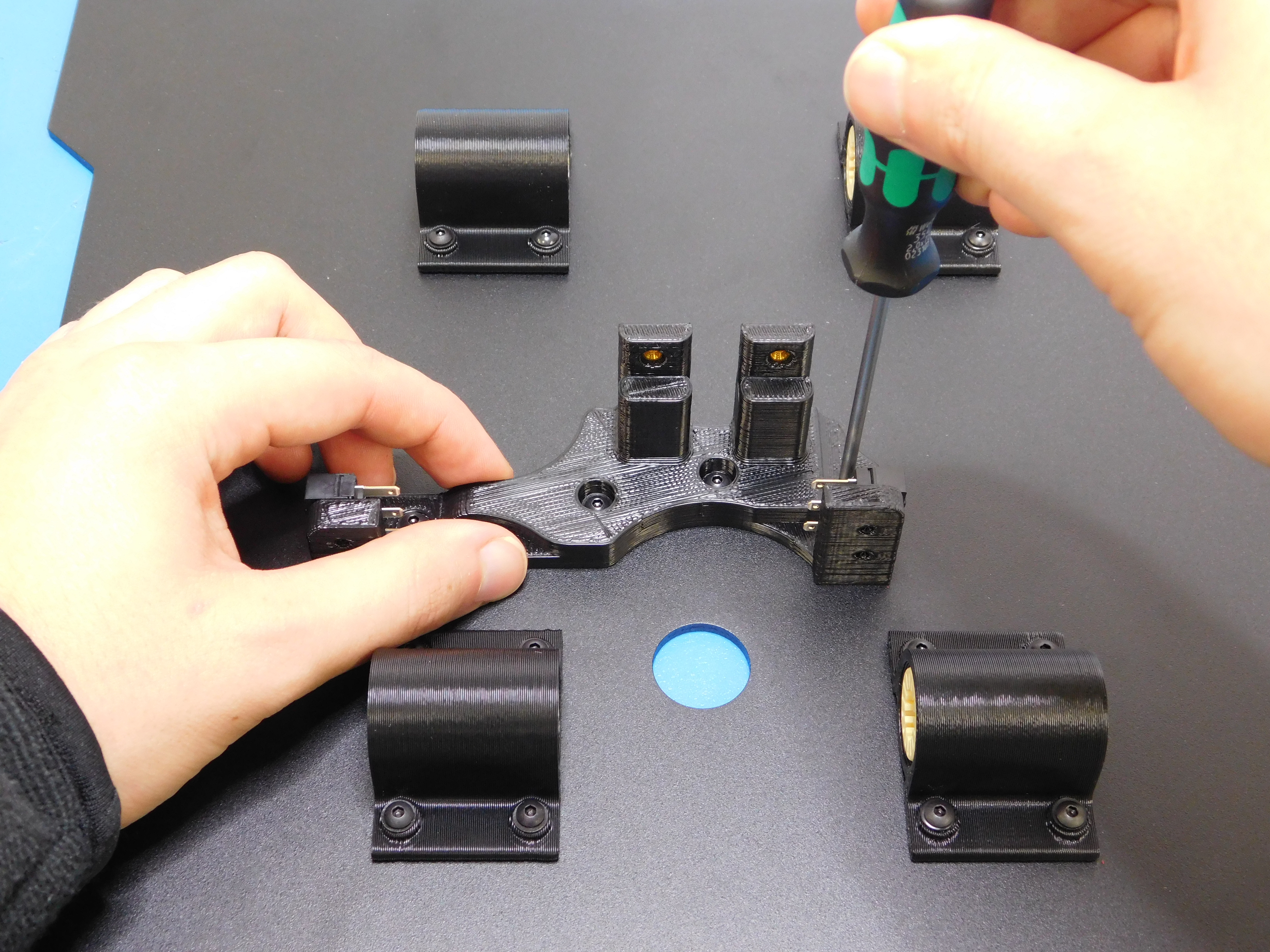
Install the belt mount as shown using four (4) M3X8 BHCS (HD-BT0137) and four (4) M3 Black Washers (HD-WA0038) due to the hole locations, the belt mount can only be installed one direction.
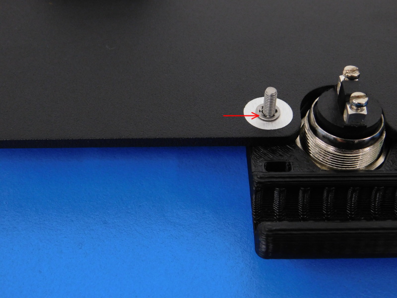
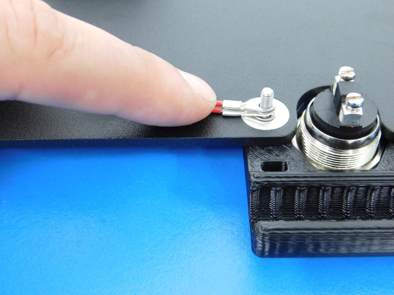
Place an Internal Tooth Lock Washer onto the stainless screw protruding from the bottom of the plate and place the 2 terminal rings onto it, following with an M3 Nyloc Nut.
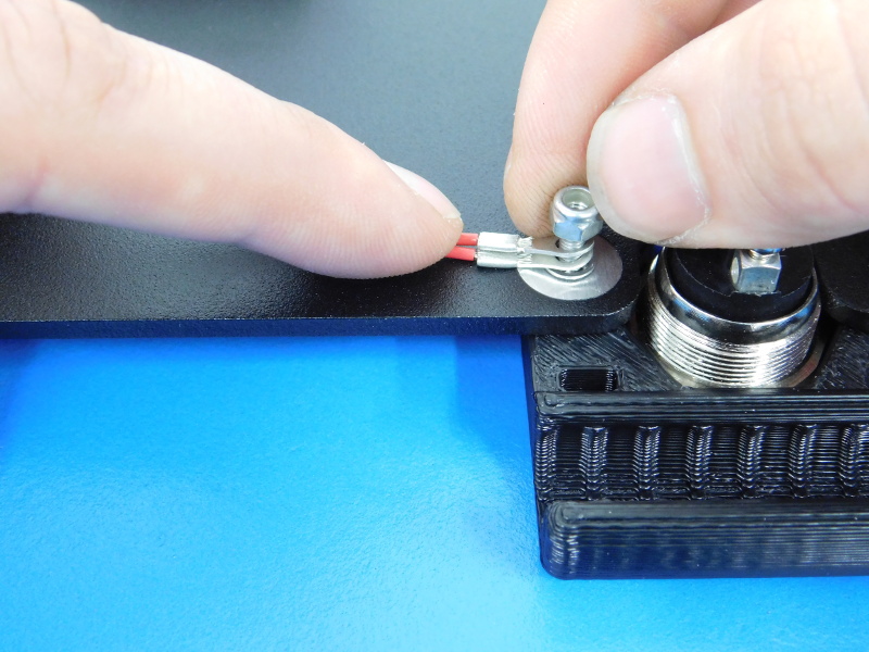
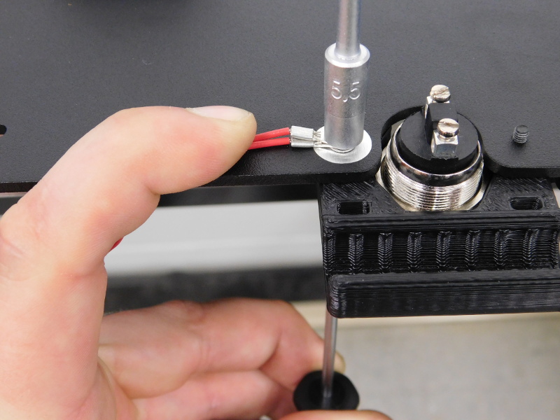
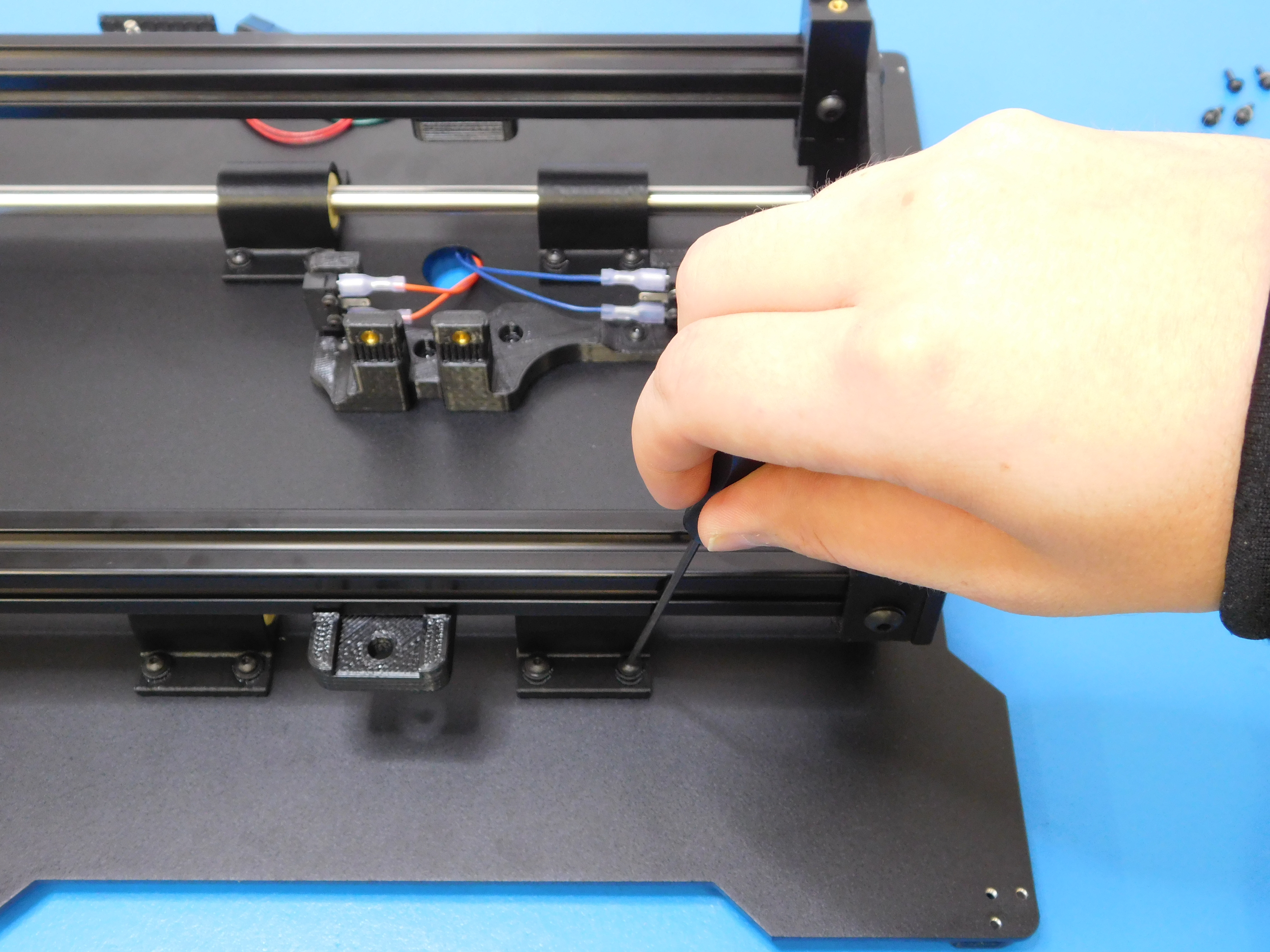
Using your 2mm Hex Driver on the top side of the plate, and your 5.5mm Nut Driver on the underside, tighten the ground terminals so they cannot move and are pointing away from the Z-Min Switch, as pictured.
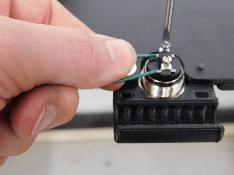
Locate the two green wires and insert the ferrules at the wire ends into the terminals of the Z-Min Switch, and tighten using the small bladed standard screwdriver.
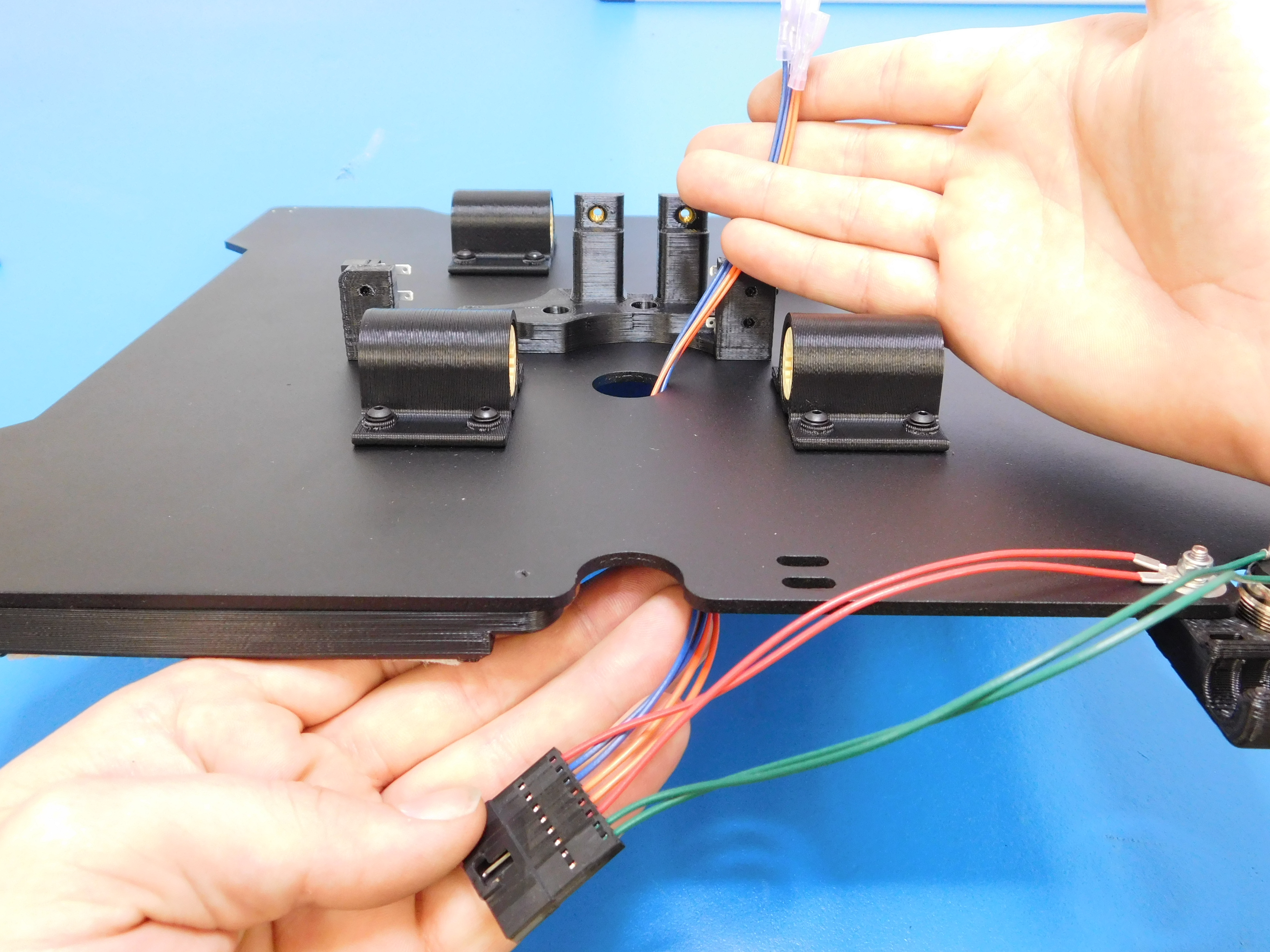
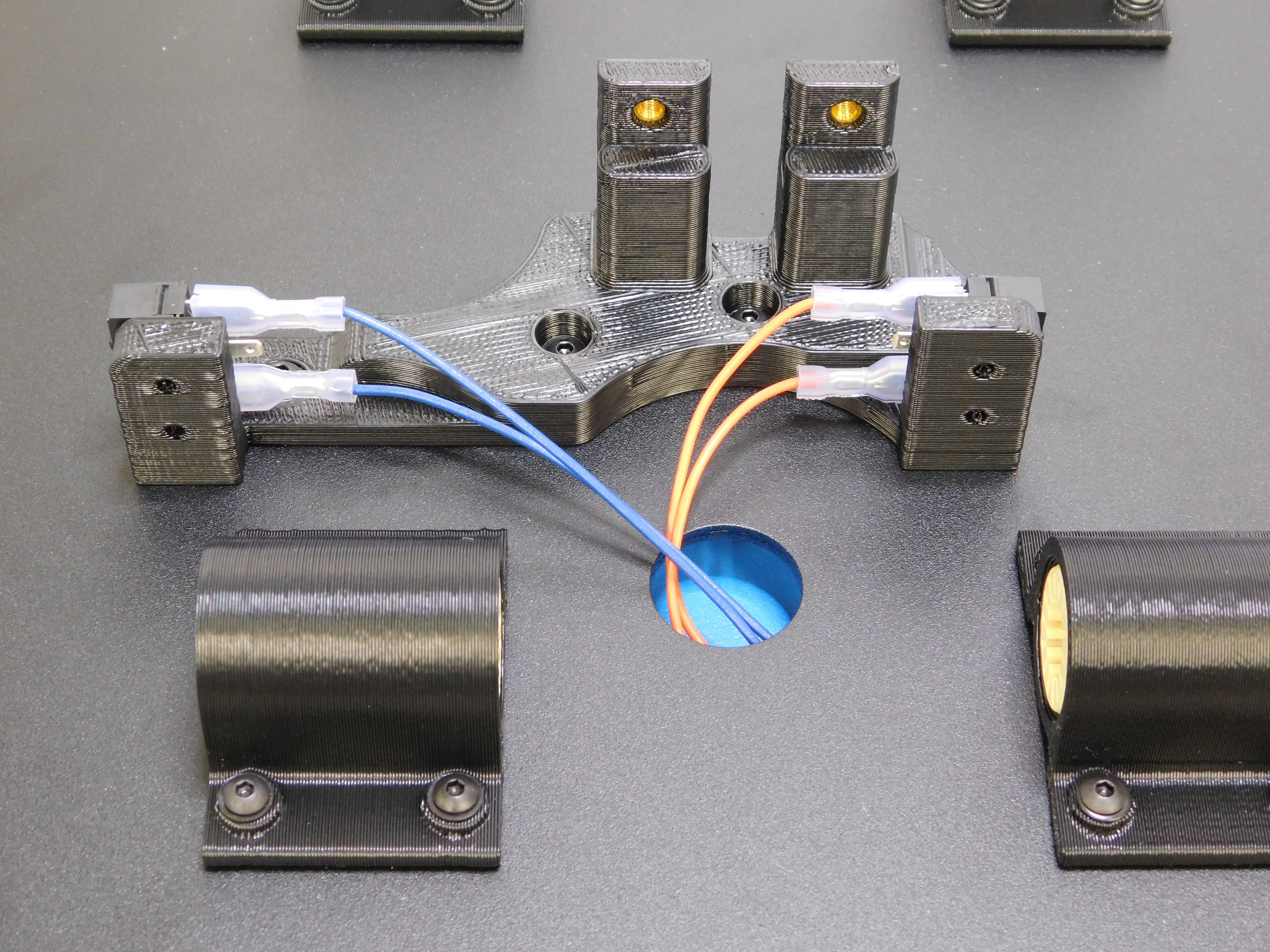
Feed the orange and blue leads over the top of the Bed Plate, and through the hole in the center. The orange leads will connect to the switch on the shorter side of the Belt Mount (rear side of the plate) and the blue leads to the longer side (front side of the bed plate). Make sure the center terminal on both switches is open.
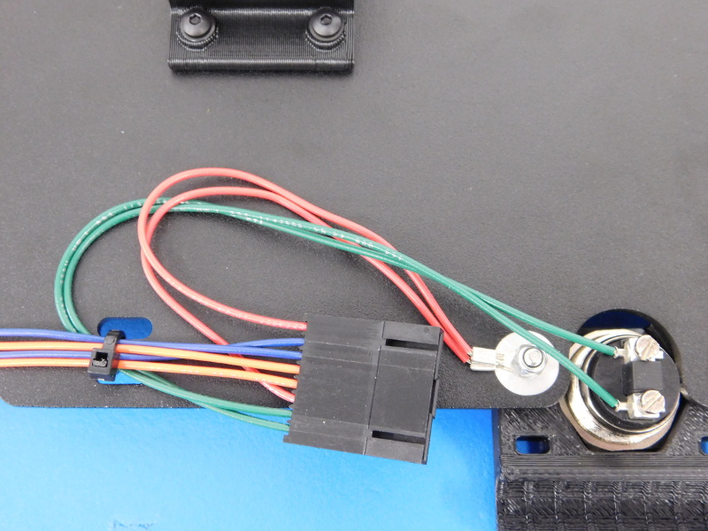
Zip tie the harness to the Bed Plate, as pictured, making sure to leave the red wires out of the zip tie to prevent excessive bend on the wires. Cut the zip tie flush at the knot with your flush cutters.
Parts:
2x- 500mm Aluminum Extrusions tapped on both ends (HD-EX0062)
24x- M5x10 BHCS
24x- M5 Black Washer
16x- M5 T-Nut
4x- Bed Mount Table v3.1 (PP-GP0224)
1x- Y-Motor End Assembly (AS-PR0030)
1x- Y-Idler End Assembly (AS-PR0028)
2x- Y-Corner Left (AS-PR0027)
2x- Y-Corner Right (AS-PR0026)
Tools:
3mm Ball Tip Hex Driver
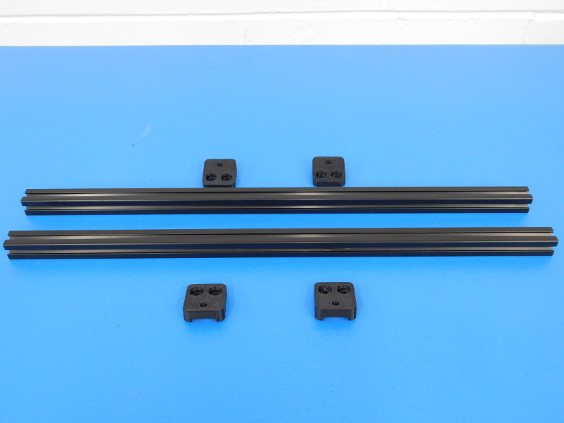
Carefully lay the two aluminum extrusions on your workbench.
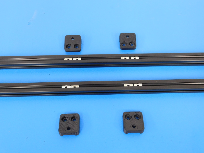
In the upward facing slot on both extrusions, insert four (4) M5 T-Nuts (HD-NT0053).
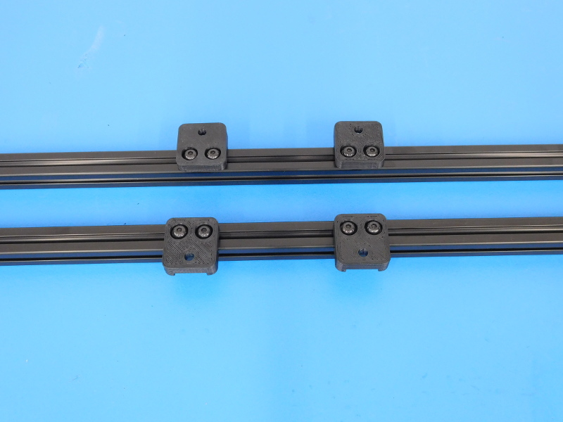
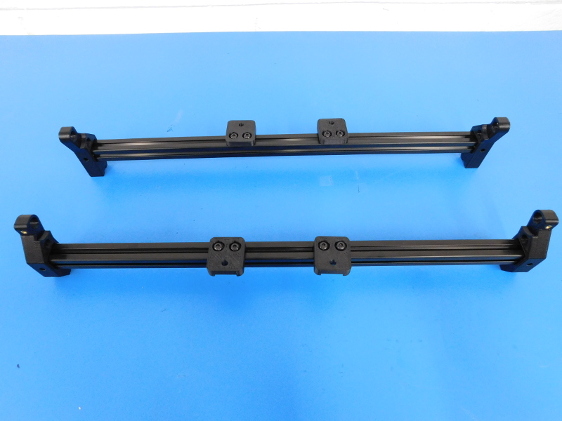
Attach two (2) Bed Mount Tables (PP-GP0224) to each extrusion using two (2) M5x10 BHCS (HD-BT0073) with washers (HD-WA0040) and the T-Nuts installed in the top of the extrusion. Make sure the Bed Mount Tables face outwards, away from each other. These may be left loose for positioning at final assembly.
Attach one Y-Corner Left (AS-PR0027) and one Y-Corner Right (AS-PR0026) on to the ends of each extrusion, perpendicular to the Bed Mount Tables installed previously, with the M5 insert facing out. See Picture
Slide a T-Nut into each left and right slot of both extrusions on both ends.
Secure the Y-Corners using one M5x10 BHCS with washer on each side of each Y-Corner. Make sure the plastic Y-Corners are flush with the end of the extrusions when tightened.
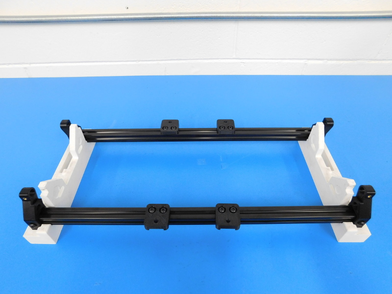
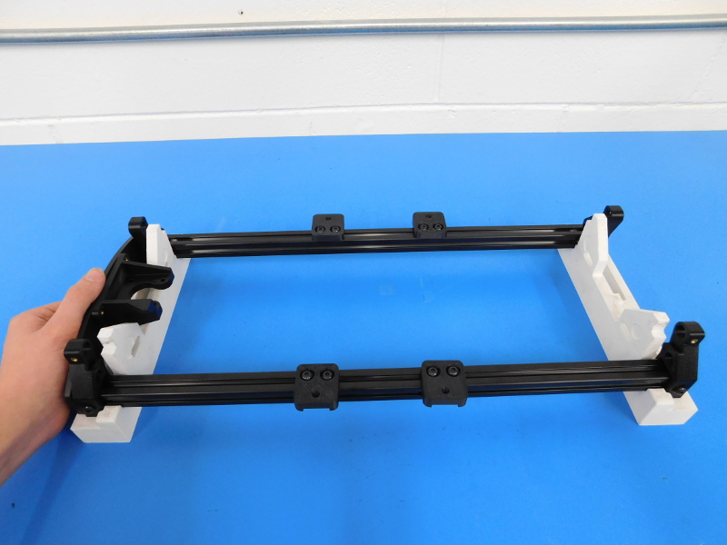
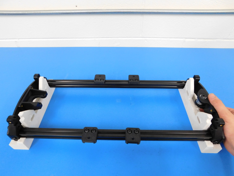
Place the frame sides into the alignment jig, as pictured.
Using four M5x10 BHCS (HD-BT0073) with washers (HD-WA0040), loosely attach the Y-Motor End Assembly (AS-PR0030) to the end of the frame to your left. One M5x10 into the threaded end of each extrusion, and the other into the M5 insert on each Y-Corner.
Using four M5x10 BHCS (HD-BT0073) with washers (HD-WA0040), loosely attach the Y-Idler End Assembly (AS-PR0028) to the end of the frame to your right. One M5x10 into the threaded end of each extrusion, and the other into the M5 insert on each Y-Corner.
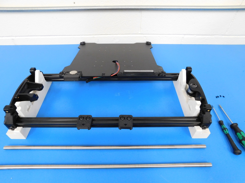
Gather the following parts and tools:
2x- 10mmx500mm Smooth Rods (HD-RD0018)
4x- M3x6 Set Screws (HD-BT0012)
Tools:
1.5mm Hex Driver
Torque Driver 2 in*lbs
3mm Hex Driver
2mm Ball Tip Hex Driver
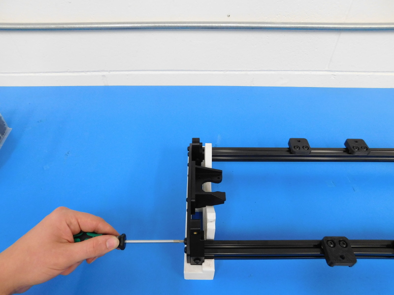
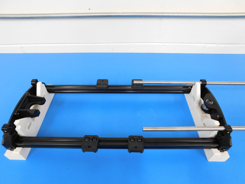
Insert the 10mm Smooth Rods beginning from the Idler side, a little less than half way.
The Y-Motor End should be towards your left.
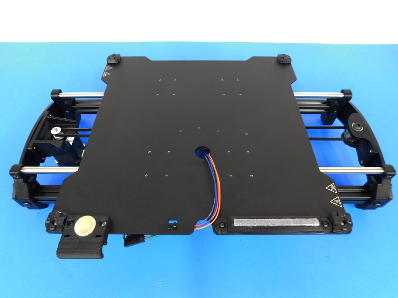
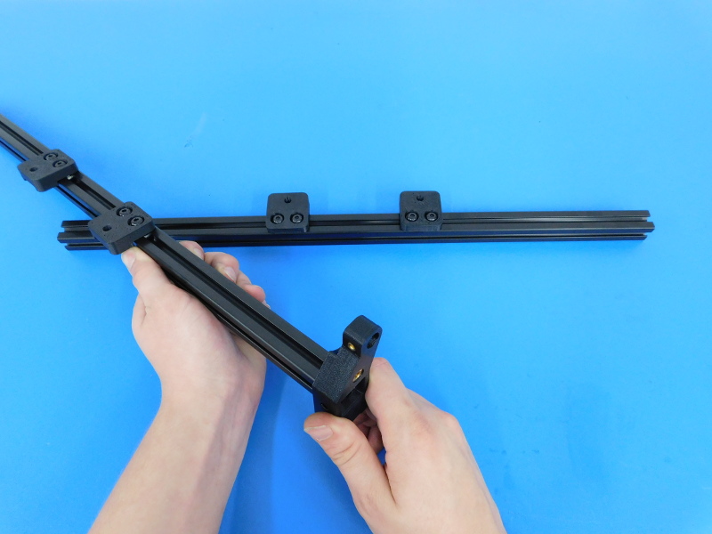
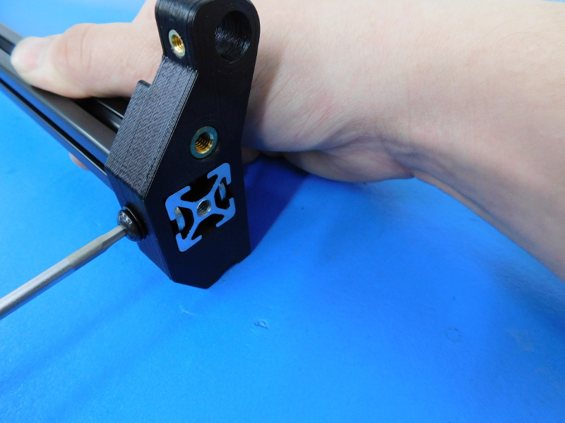
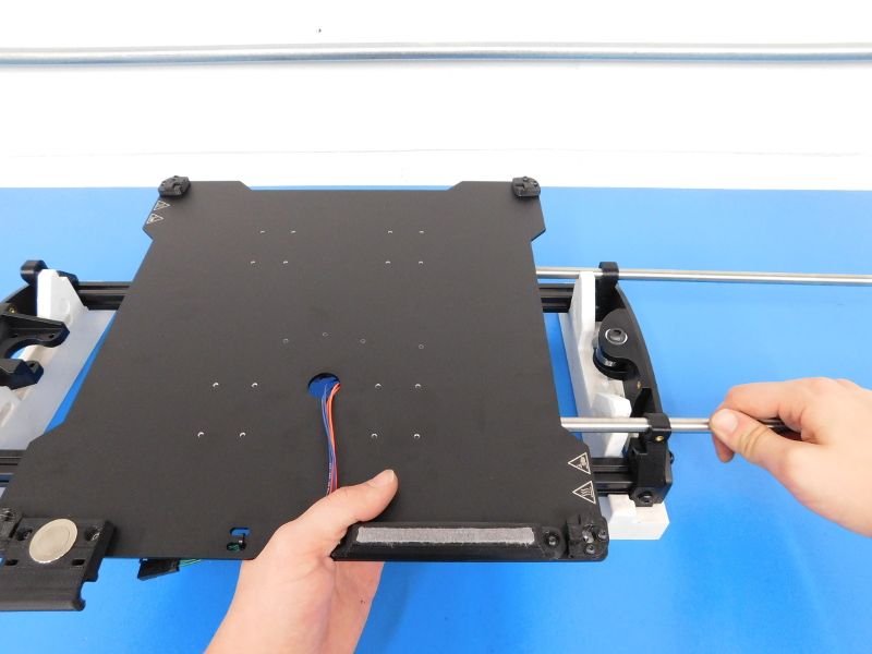
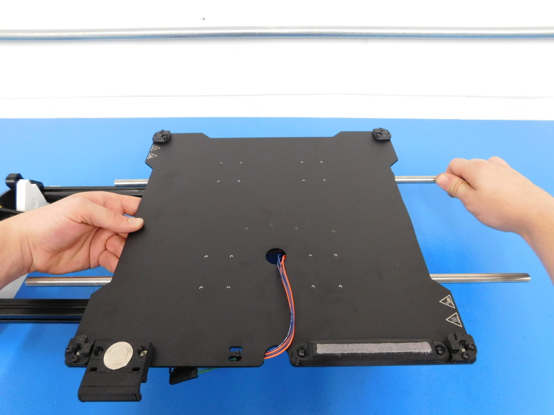
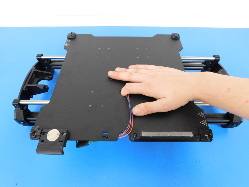
Grasp the harness side of the Bed Plate assembly completed in step 4 with your left hand, while guiding the Smooth Rods through the bearing holders on the bottom side of the Bed Plate.
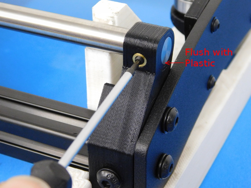
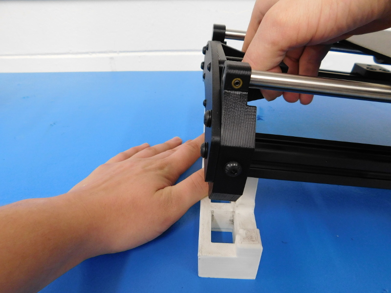
Continue to guide the Smooth Rods into the opposing Y-Corners until the ends of the Smooth Rods are flush with the plastic on the front (Y-Idler End).
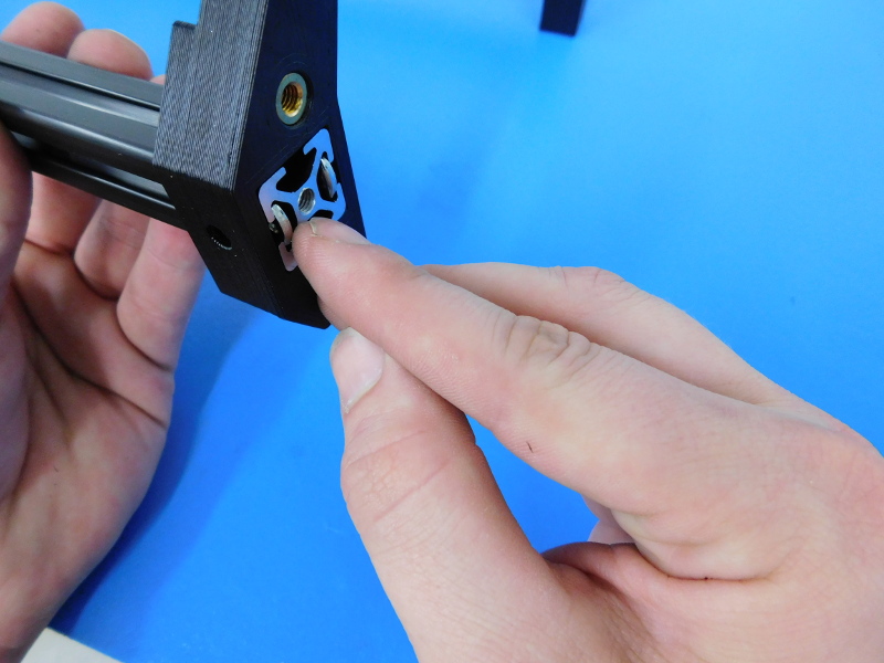
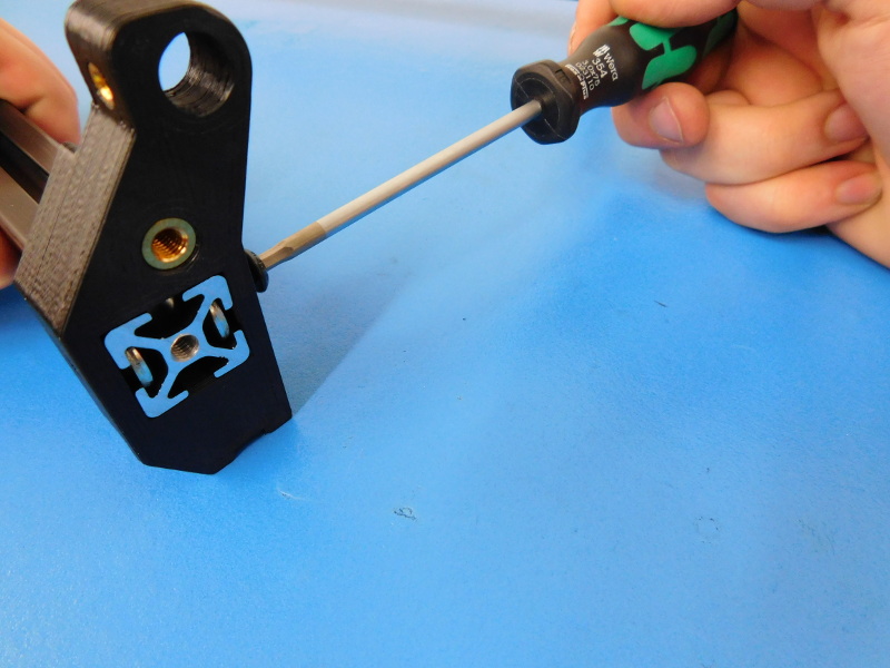
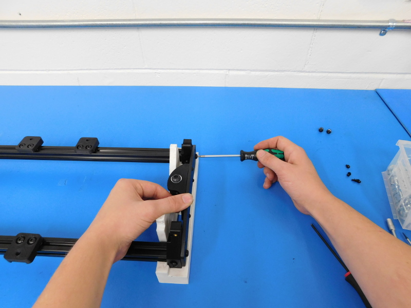
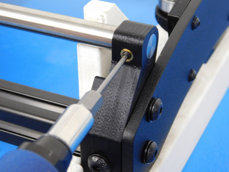
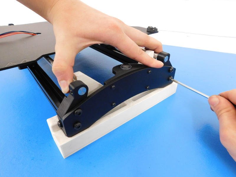
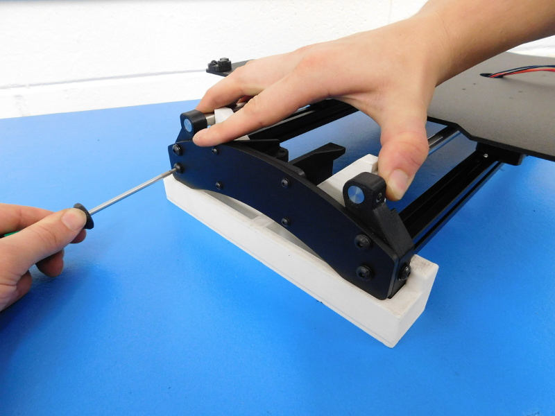
Using the 1.5mm Hex Driver, Install one M3x6 Set Screw (HD-BT0012) into the M3 insert on EACH Y-Corner as pictured and torque with the 2 in*lbs Torque Driver.
Ensure that the assembly is fully seated in the Y Alignment Jig, both Idler and Motor Ends should rest on the jig as well.
Beginning on the Idler End;
Lightly grasp between both Smooth Rods near the Alignment Jig to make sure the Smooth Rods rest against the jig.
Starting with the two bottom screws on one then moving to the top screws of that side, Tighten the four (4) M5X10 BHCS to hand tight; repeat for the other side (bottom first, then top).
Once all frame screws have been tightened, lift the assembly to remove the Y-Alignment Jig and flip the assembly over.
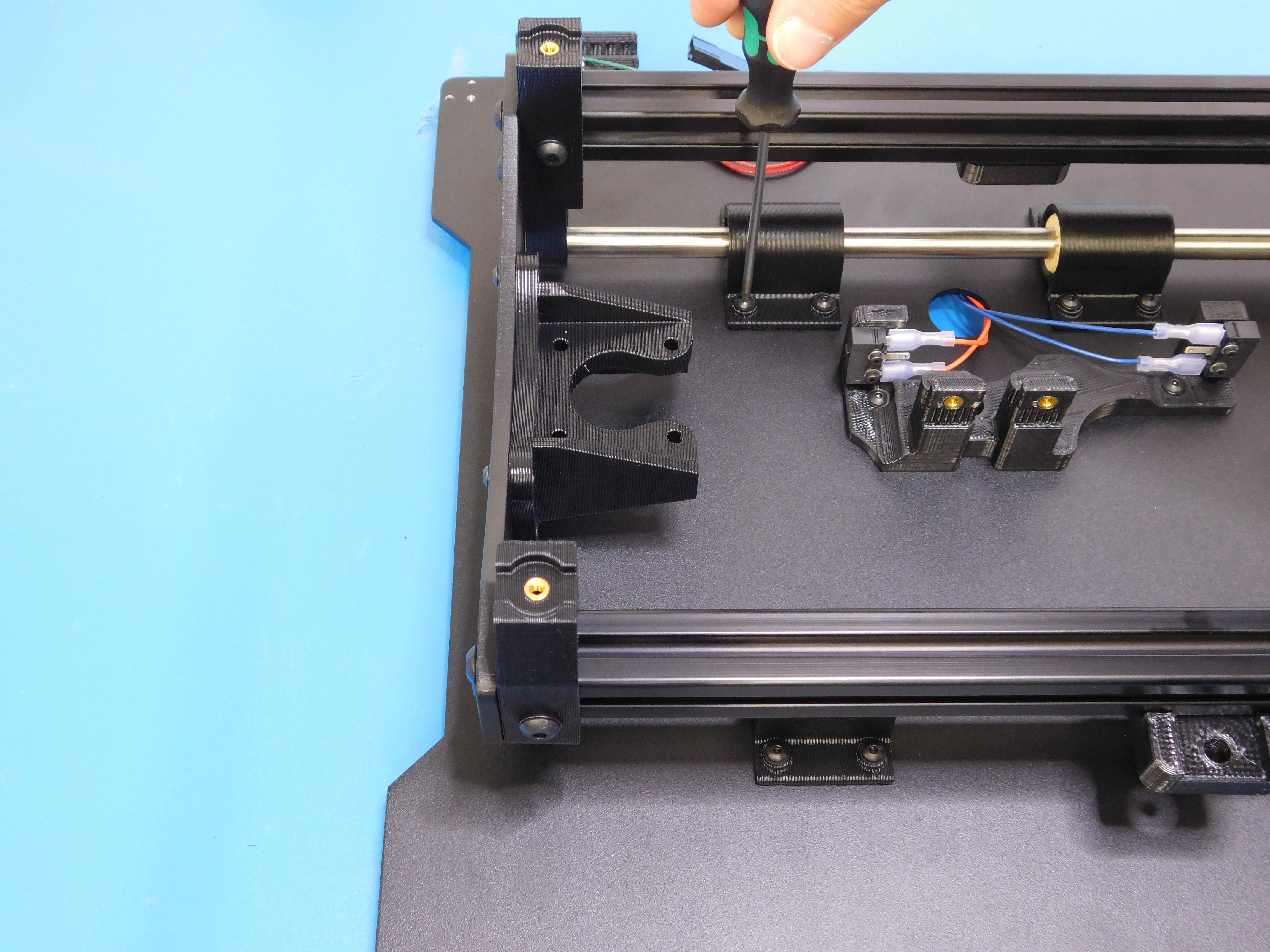
Slide the frame so that the bed assembly is towards the motor side of the assembly and tighten the motor side Bearing Holders to the Bed Plate using the 2mm Ball Tip Hex Driver.
Slide the frame towards the Idler End and tighten the idler side bearings to the Bed Plate.
Flip the assembly over and ensure the bed plate slides smoothly from end to end. If any binding occurs you may have to loosen and re-tighten the bearing holders as described above.
Gather the following parts and tools:
Parts:
1x- NEMA 17 Moons Motor (EL-MT0029)
1x- GT2 Timing Pulley (HD-MS0033)
4x- M3x12 BHCS (HD-BT0146)
4x- M3 Black Washers (HD-WA0038)
Tools:
Y-Pulley Spacer (3.4mm)
1.3mm Hex Driver
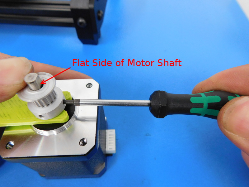
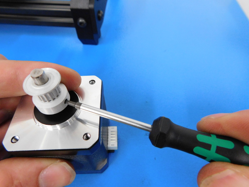
First attach the Timing Pulley to the motor shaft, using the Y-Pulley Spacer as pictured to set a height of 3.4mm. Ensure that the first set screw to be tightened is to the flat side of the motor shaft. Tighten both Set Screws firmly with the 1.5mm Hex Driver.
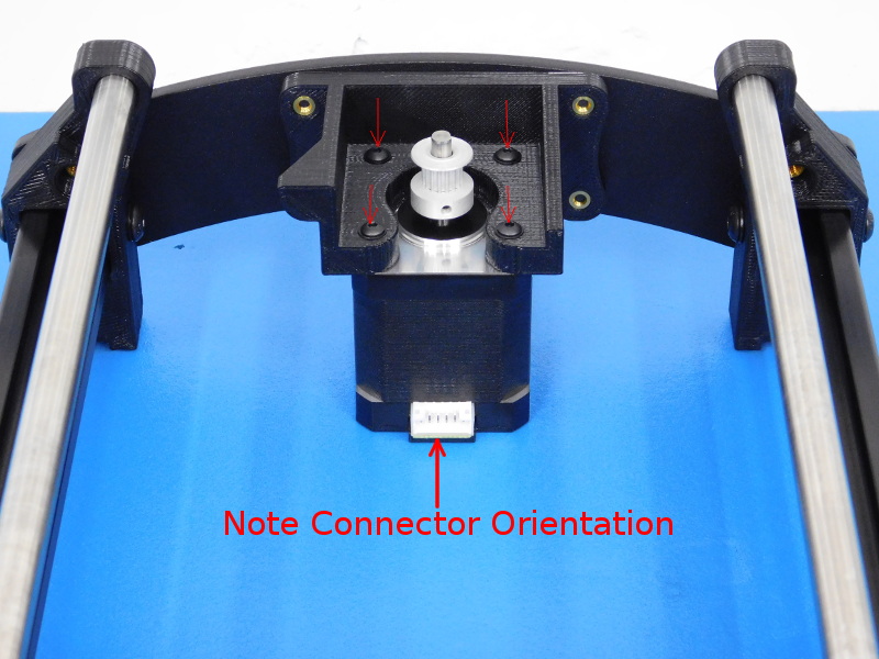
Slide the motor underneath the mount with the connector facing the inside of the assembly and secure with four (4) M3x12 BHCS (HD-BT0146) with washers (HD-WA0038). Tighten firmly.
Gather the following parts and tools:
Parts:
1x- TAZ Drive Belt (HD-BL0032)
4x- Flexy Bed Feet (PP-GP0238)
4x- M3x8 BHCS (HD-BT0137)
2x- M3x12 BHCS (HD-BT0146)
6x- M3 Black Washers (HD-WA0038)
Tools:
Flush Cutters
2mm Hex Driver
Pliers
Gates Sonic Tension Meter
Carefully flip the assembly over so that the Bed Plate is resting on the work bench.
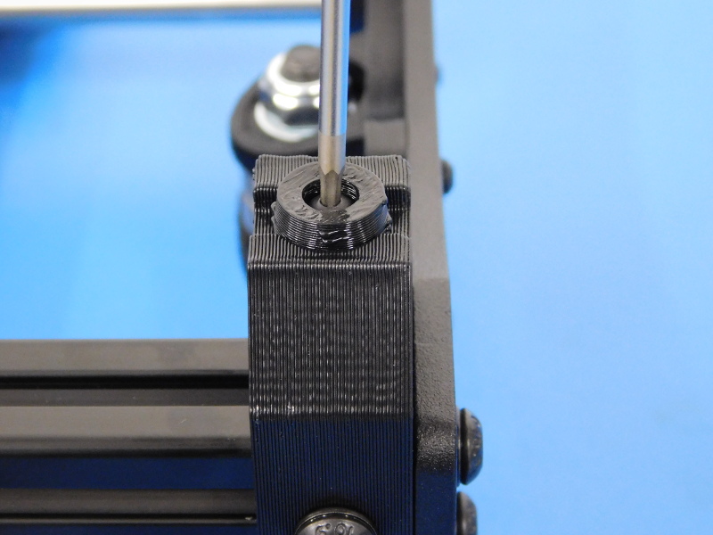
Attach one (1) Flexy Bed Foot to each Y-Corner using one (1) M3x8 BHCS (HD-BT0137) with washer (HD-WA0038), tighten until the Flexy Bed Foot cannot be rotated.
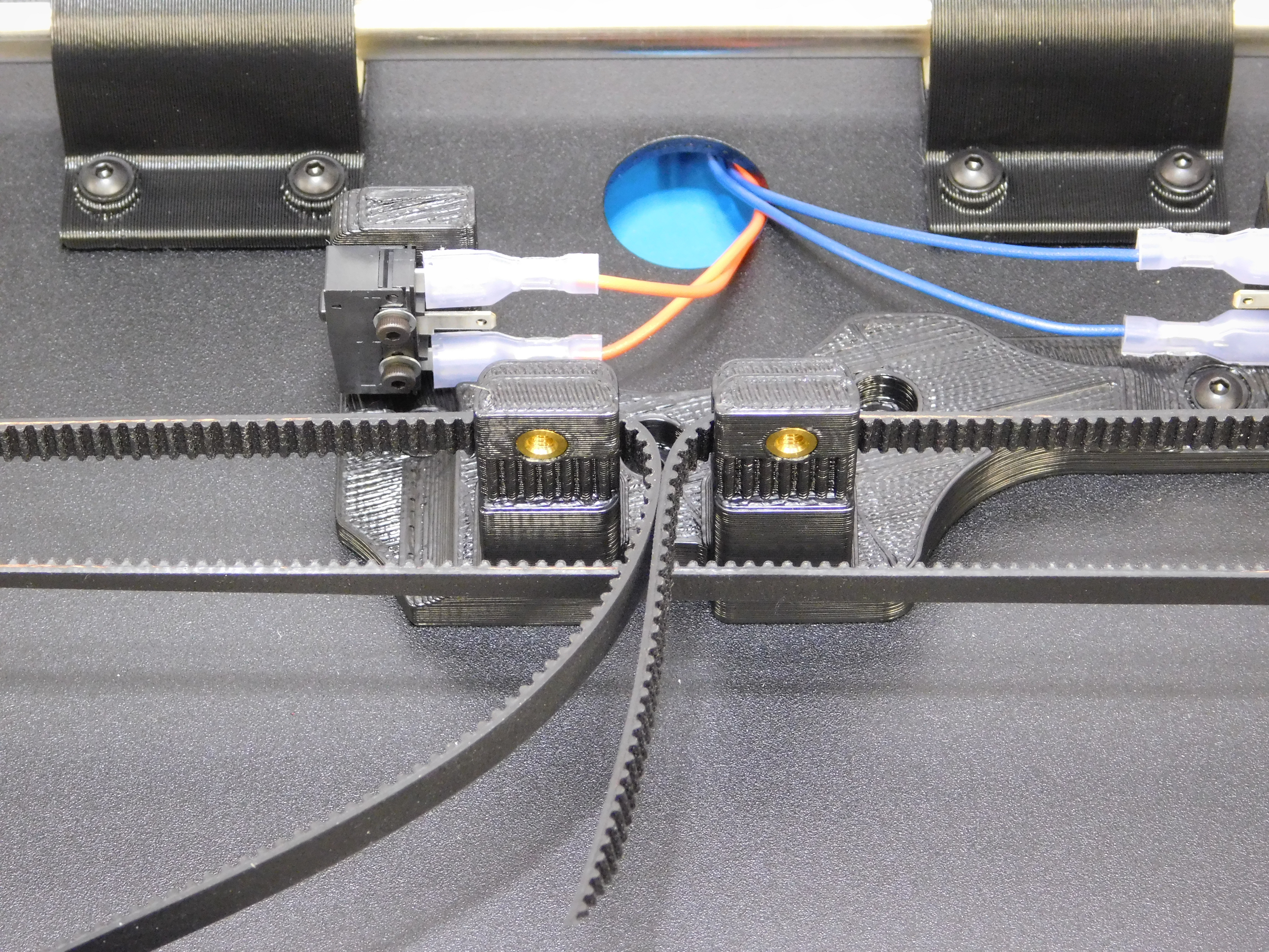
Using the flush cutters, cut the belt (HD-BL0032) at one location. It is helpful to cut the belt at an angle for feeding through the Idler.
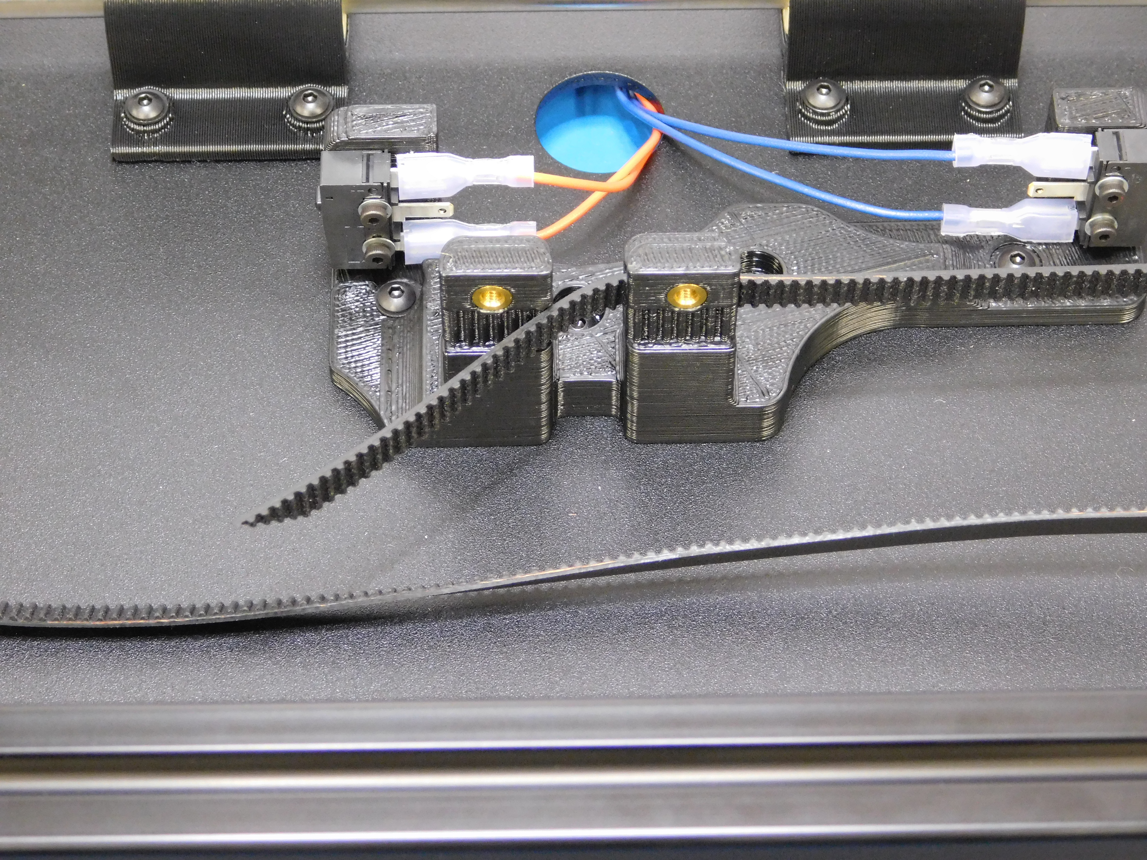
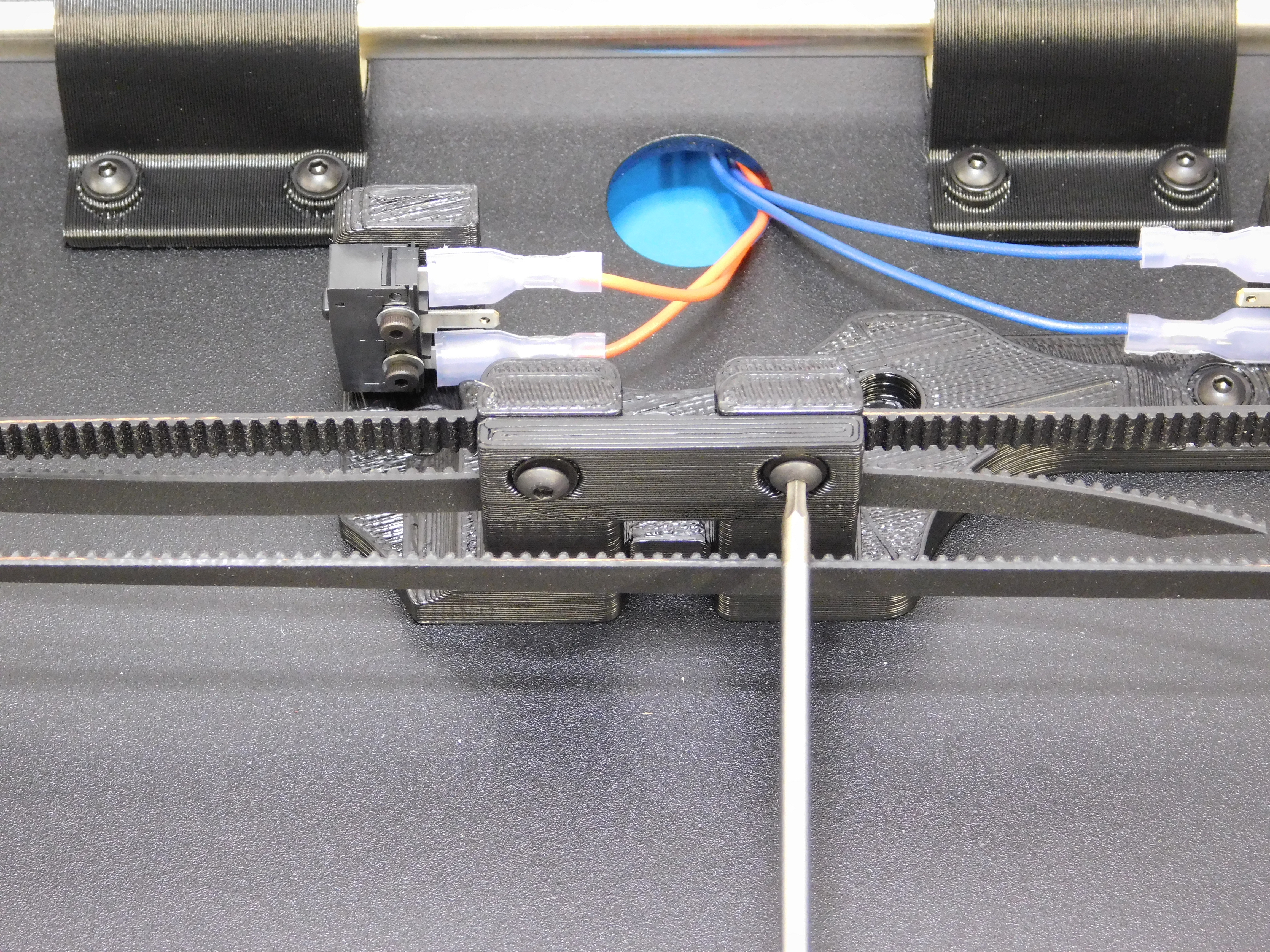
Insert the belt into the clamp closet to the Idler End, as pictured.
Feed the belt through the Idler and then loop around the motor pulley.
Insert the end of the belt into the clamp closest to the motor, as pictured.
Fold the belt ends around the clamp and install one Y-Belt Clamp (PP-GP0304) using two (2) M3x12 BHCS (HD-BT0146) with washer (HD-WA0038).
Leave the clamp screw closest to the motor loose so that the belt can be tensioned.
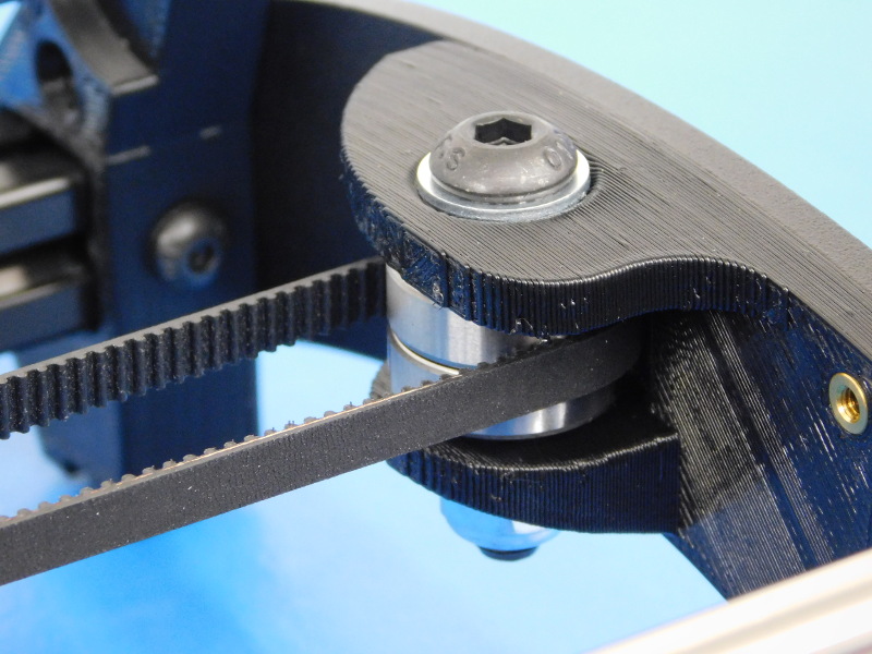
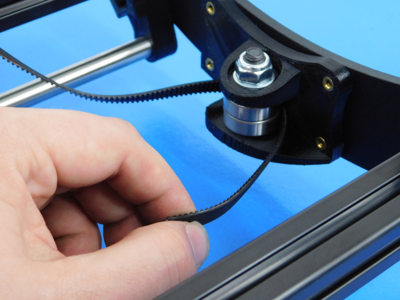
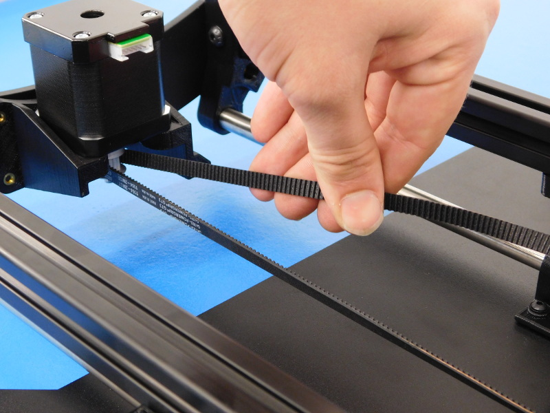
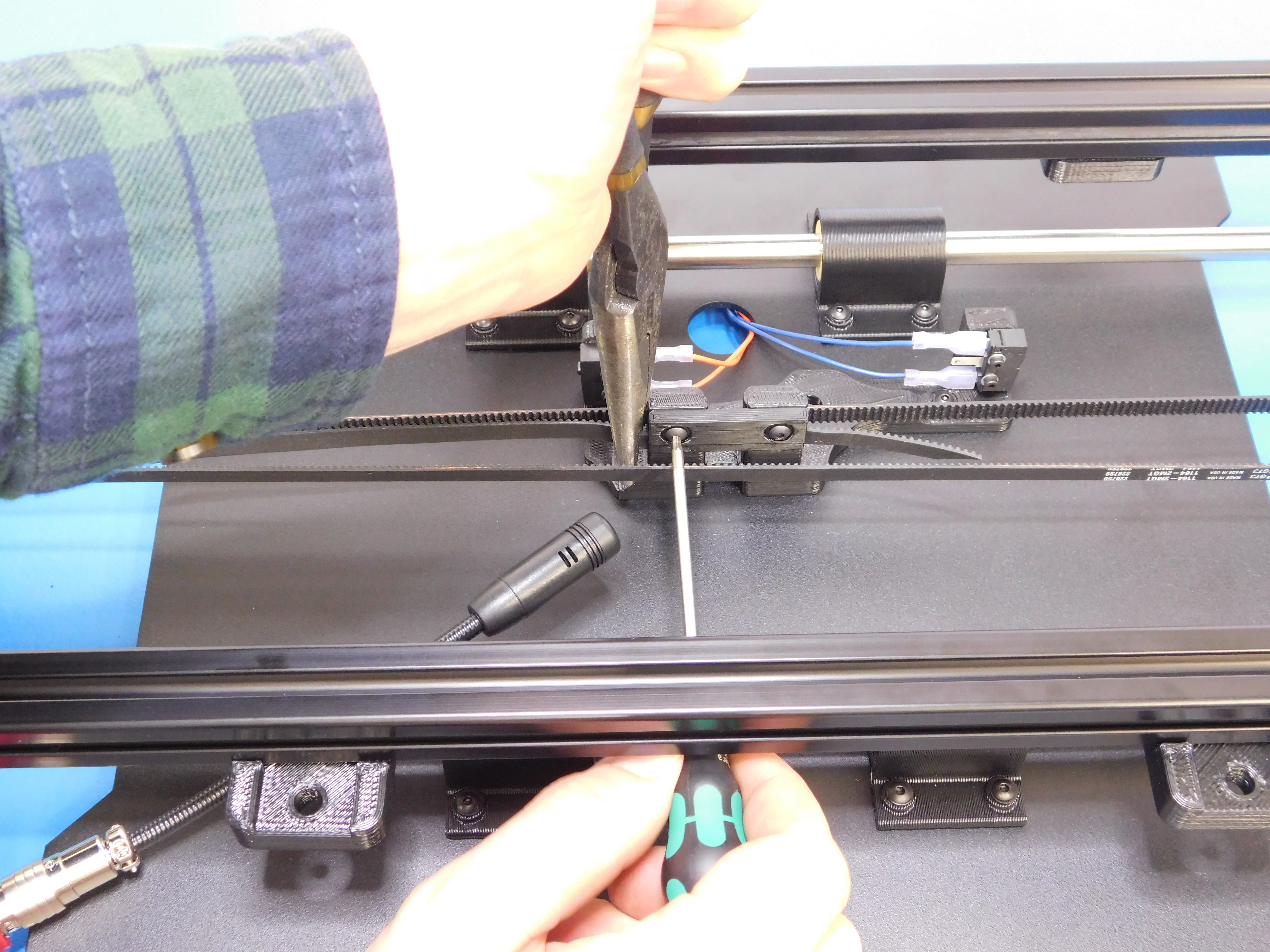
Grip the belt close to the motor side clamp, as pictured, and rotate to apply tension to the belt. Using the Gates Sonic Tension Meter, tension the belt to 23-27N. Tighten the M3x12 BHCS to clamp the belt.
Trim excess belt back, leaving enough to grip should future adjustments be needed (15mm), cut straight with the teeth of the belt.
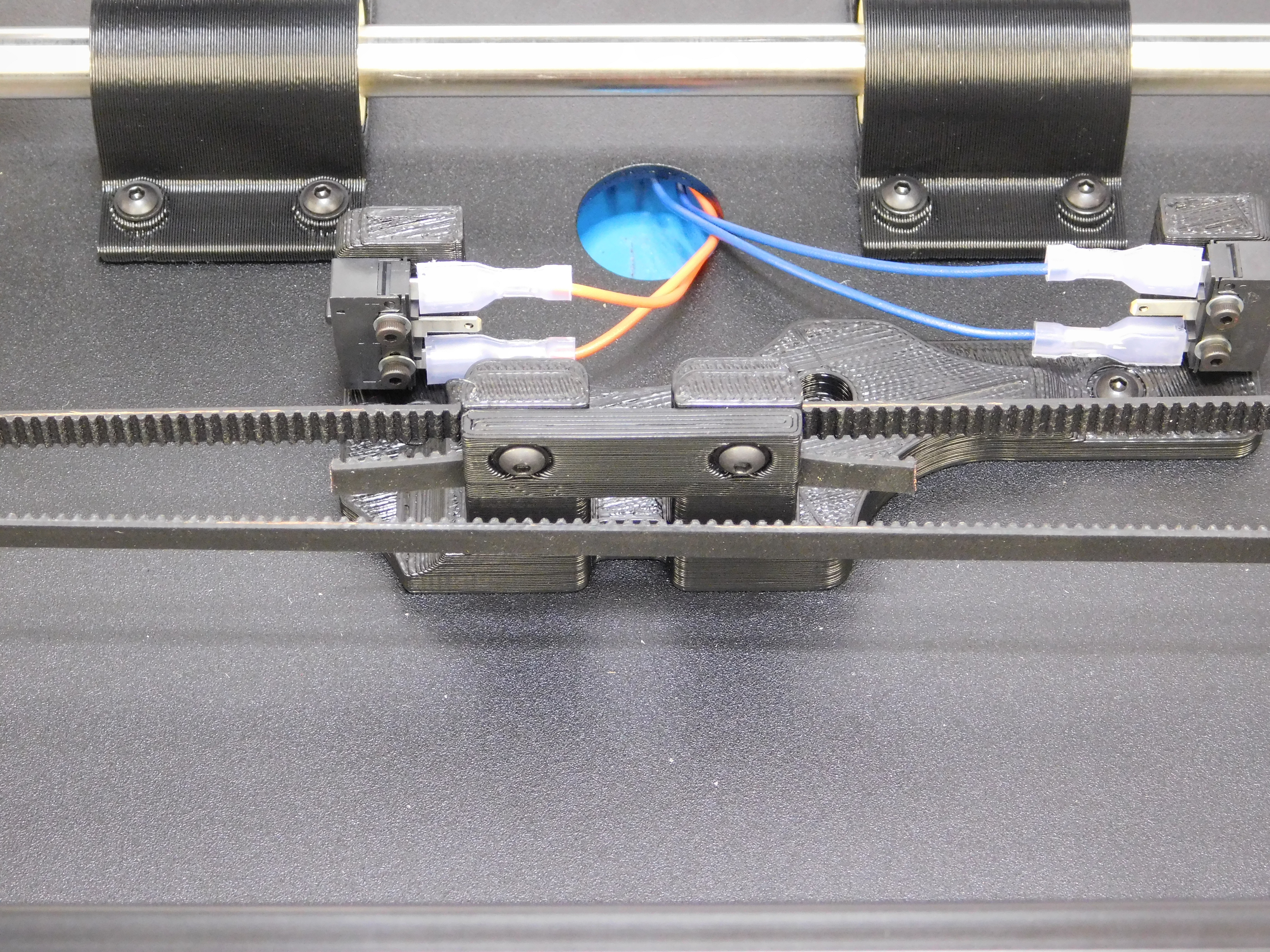
Flip the assembly upright, and ensure the bed plate slides smoothly from end to end.
While doing so, watch the height of the belt in the Y-Idler to ensure it doesn’t ride too far up or too far down. It should not contact the plastic of the Idler.
Tag the assembly with your name on a manila tag and log the assembly in your production log.