Open HardwareAssembly Instructions
Guides for installation and assembly of the LulzBot line of products made by FAME 3D LLC.
Guides for installation and assembly of the LulzBot line of products made by FAME 3D LLC.
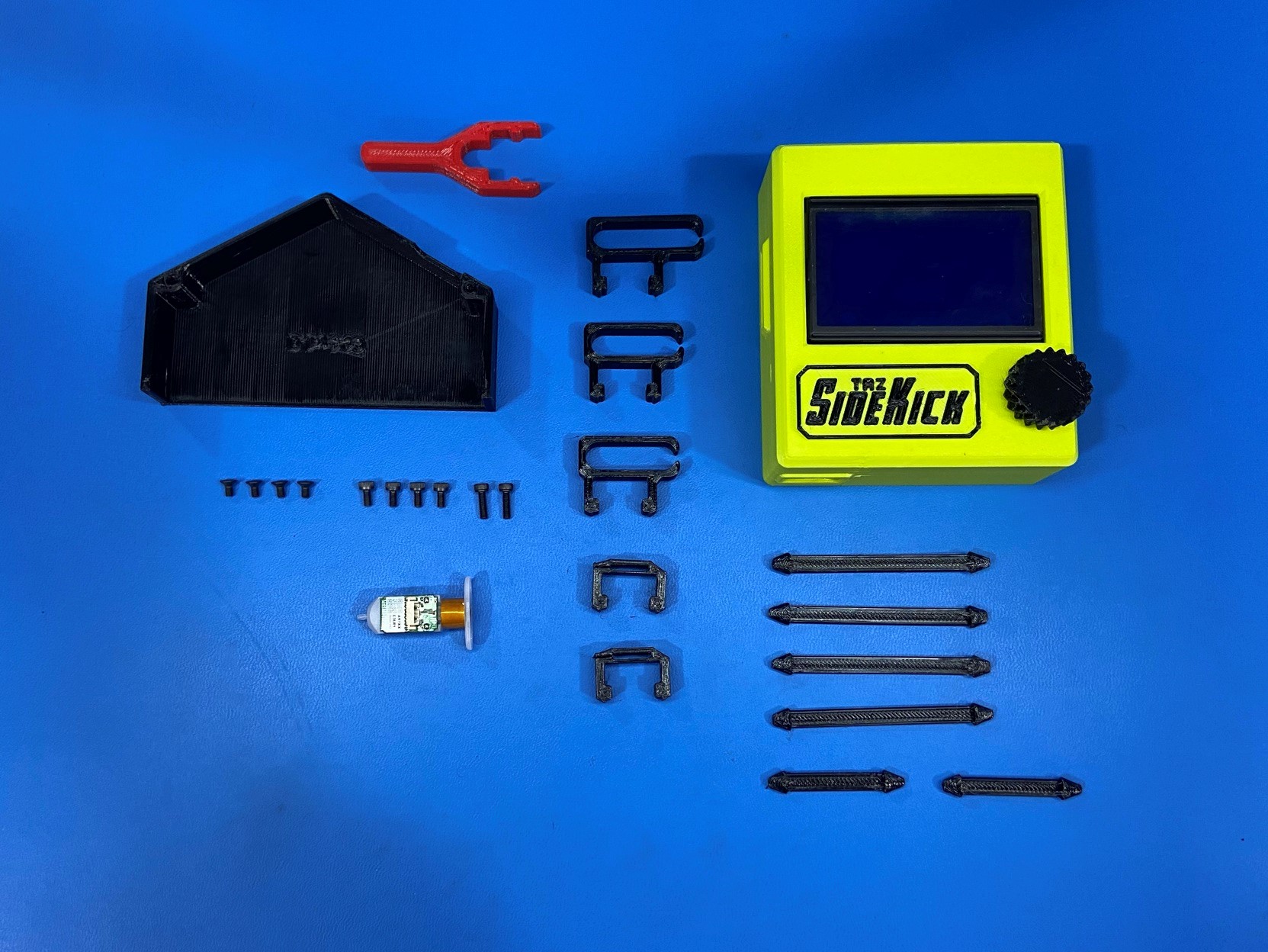
2x- [HD-BT0005] M3x10 SHCS, Black-Oxide
4x- [HD-BT0045] M3x6 SHCS, Black-Oxide
4x- [HD-BT0128] M3x6 FHCS, Black-Oxide
1x- [PP-MP0327] BLTouch Auto Bed Leveling Sensor
2x- [PP-GP0566] 3 Bundle Cable Clip
2x- [PP-GP0578] Flexy Rosebud Wrap 1
4x- [PP-GP0579] Flexy Rosebud Wrap 2
1x- [PP-GP0604] Z 747 Power Supply Bottom
2x- [PP-GP0658] LCD Cable Clip
1x- [PP-GP0679] 4 Bundle Cable Clip
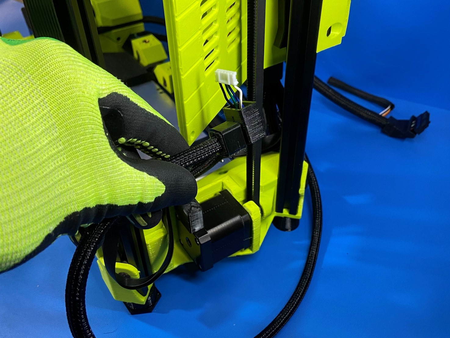
Find the LZ motor harness, should have a purple wire.
Then route the harness along the backside of the printer and slide it into the channel on the power plug housing.
Once harness is fully seated in the channel route it under the power plug harness.
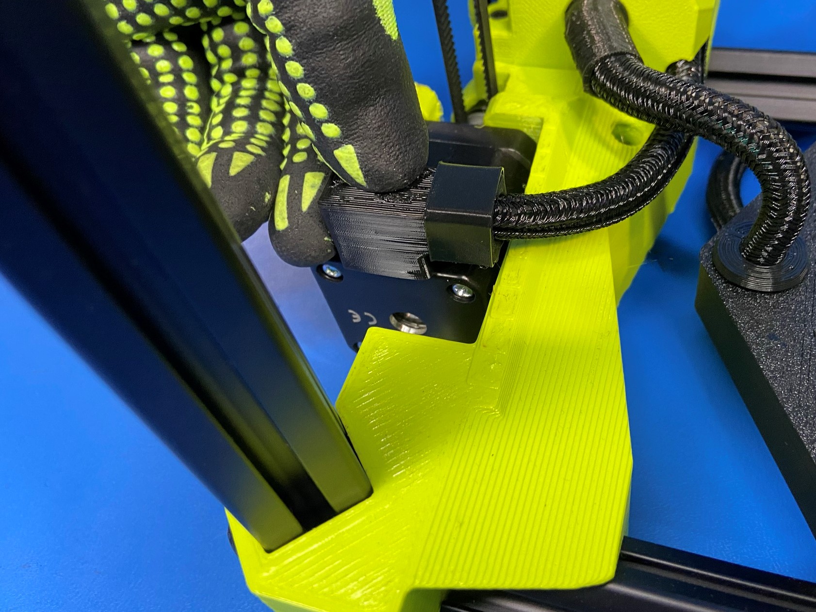
Then connect the harness to the LZ motor, make sure it has a proper connection.
Now take the harness boot and place it over the connection.

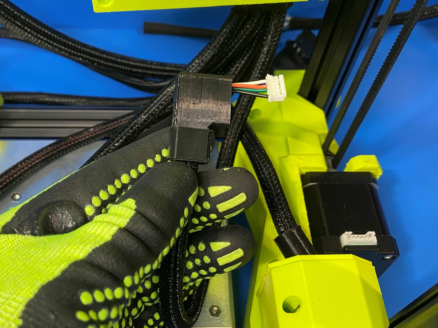
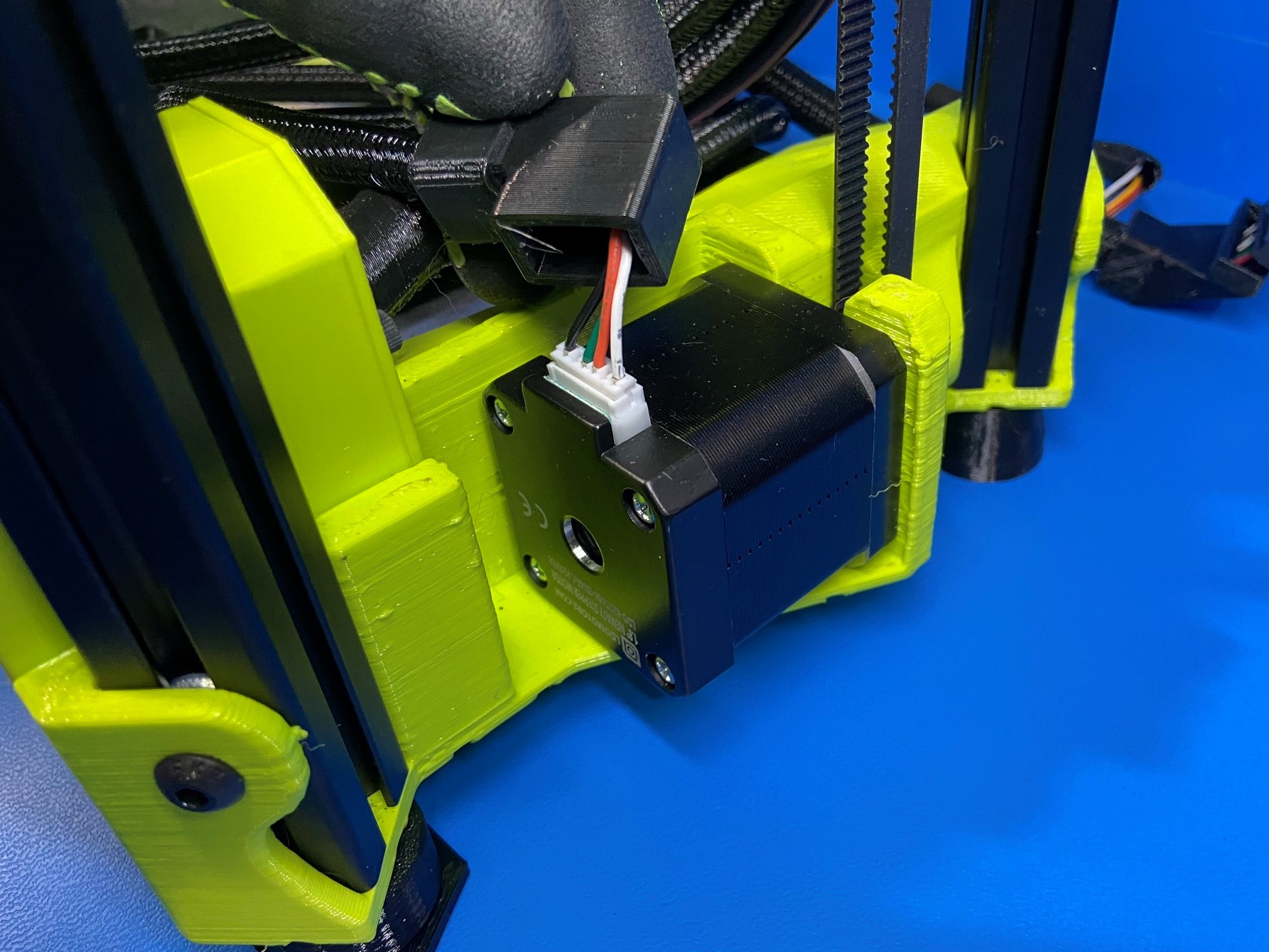
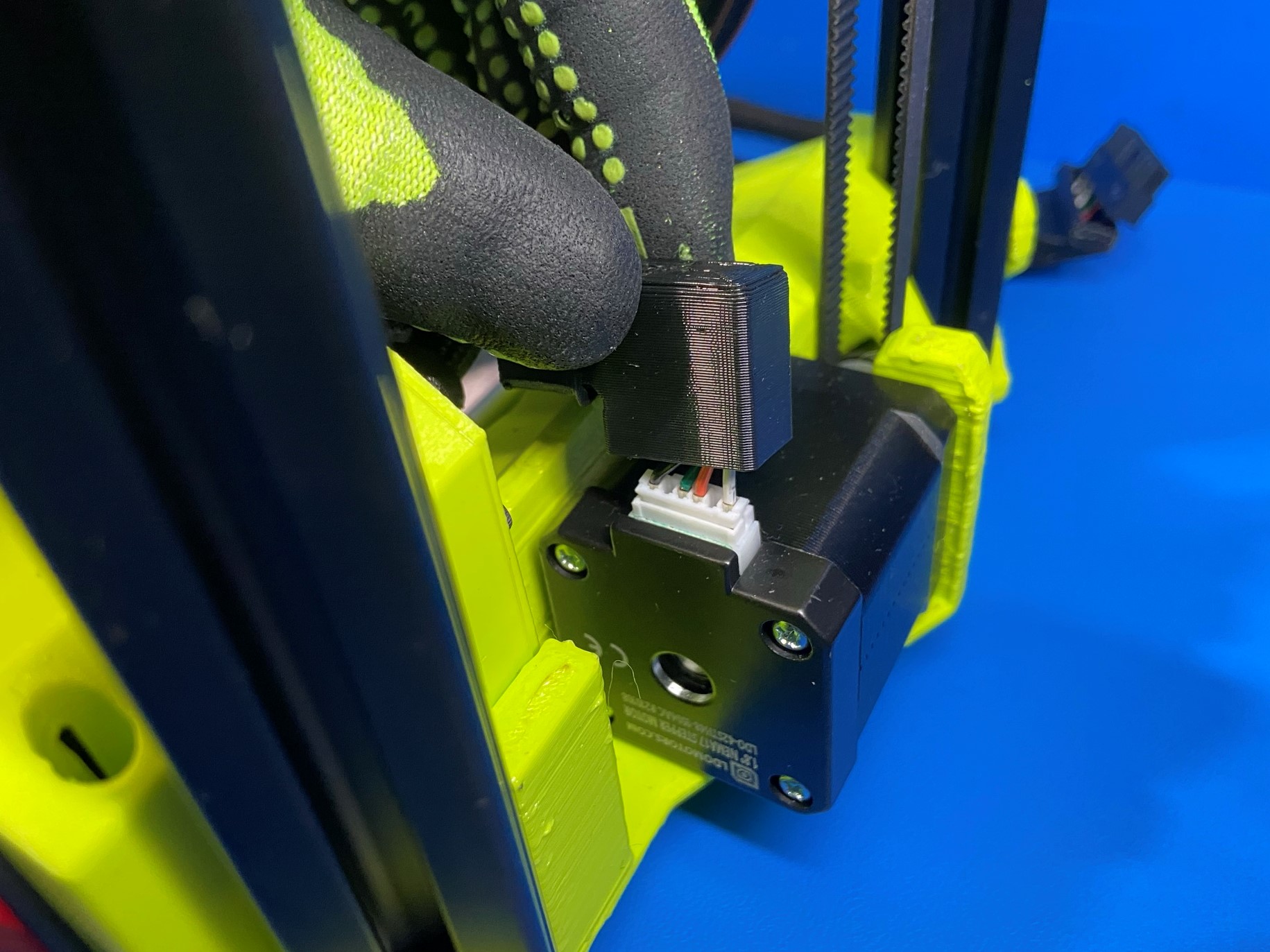
Find the RZ motor harness should have a orange wire, once you found this harness connect it to the RZ motor.
Make sure they have a secure connection then place the harness boot over the connection.
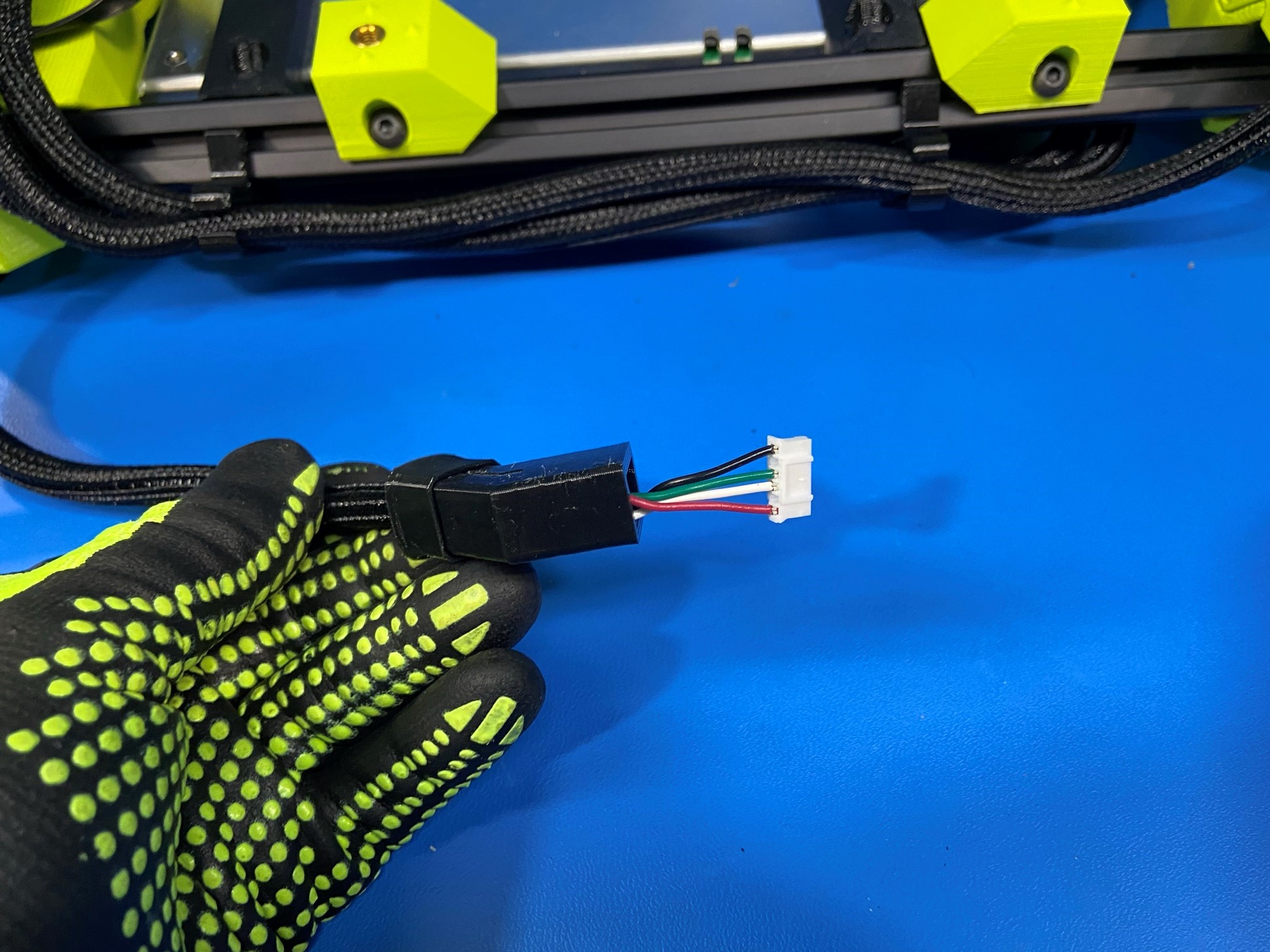
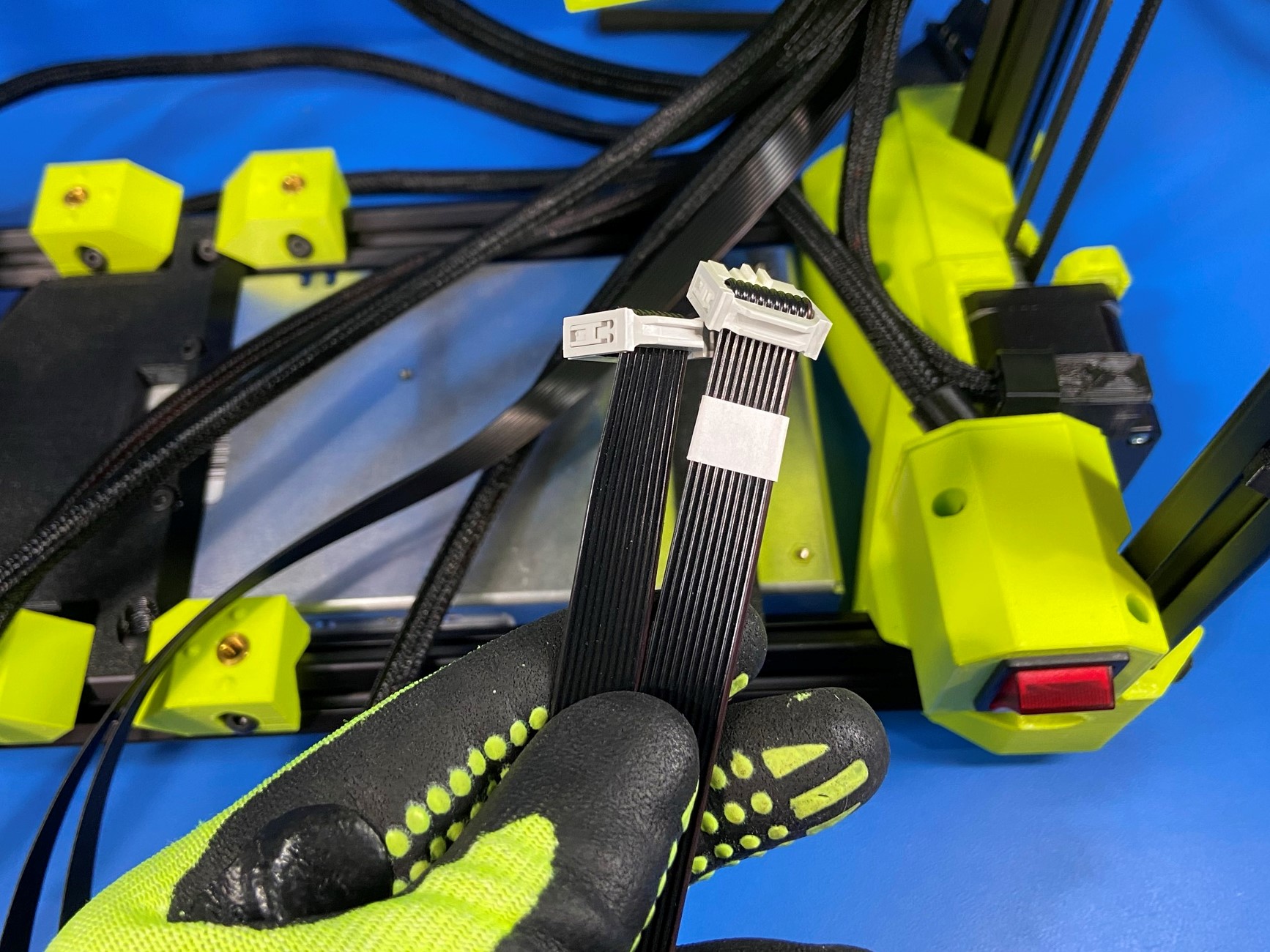
Now find both LCD harnesses and align them so that both connector are facing the same way and there is no twists in the harness.
Then route them between the power switch harness and the RZ harness.
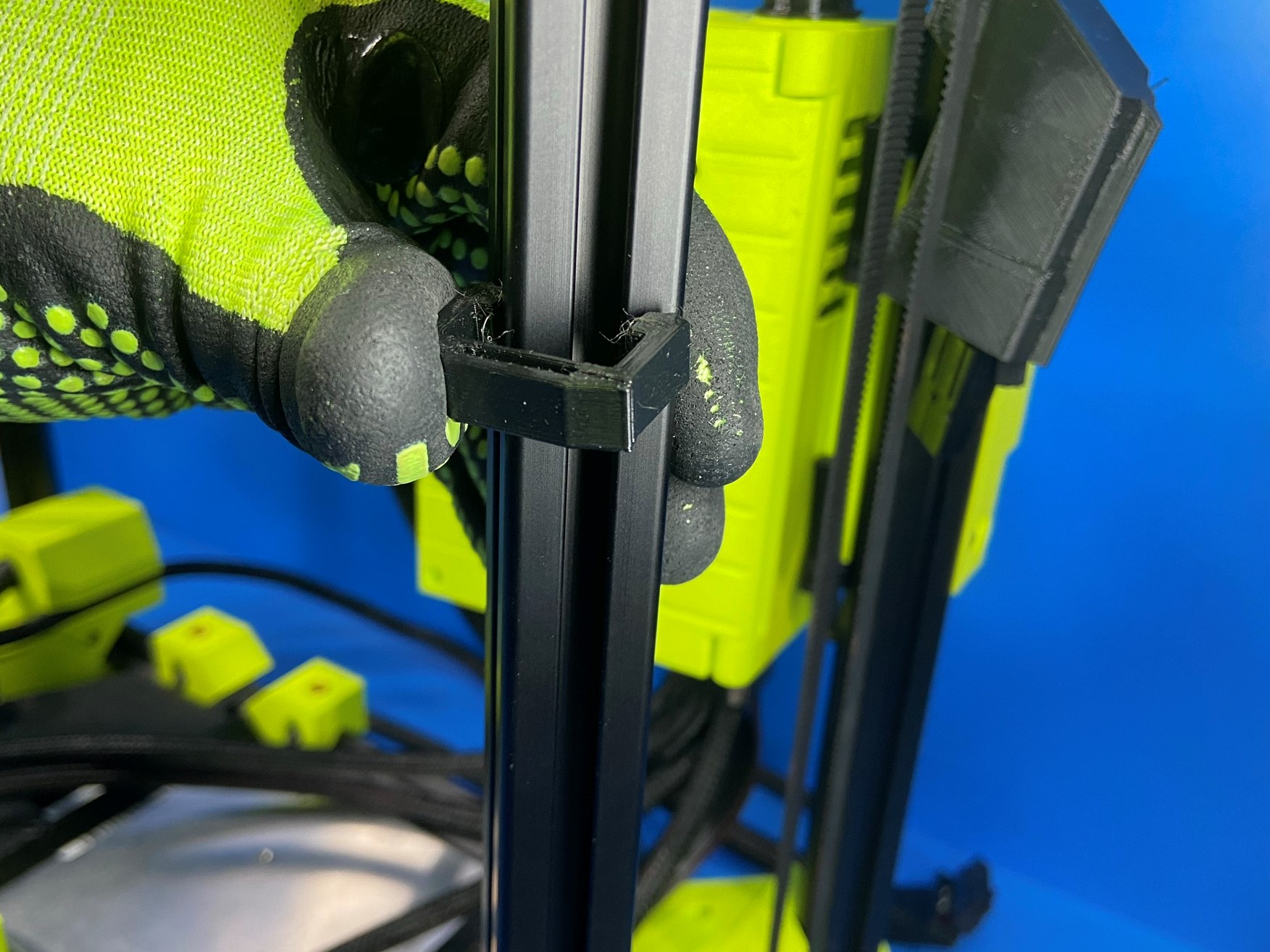
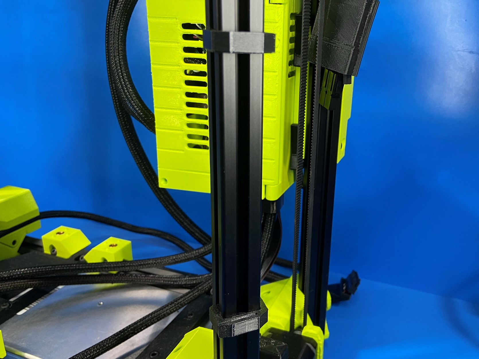
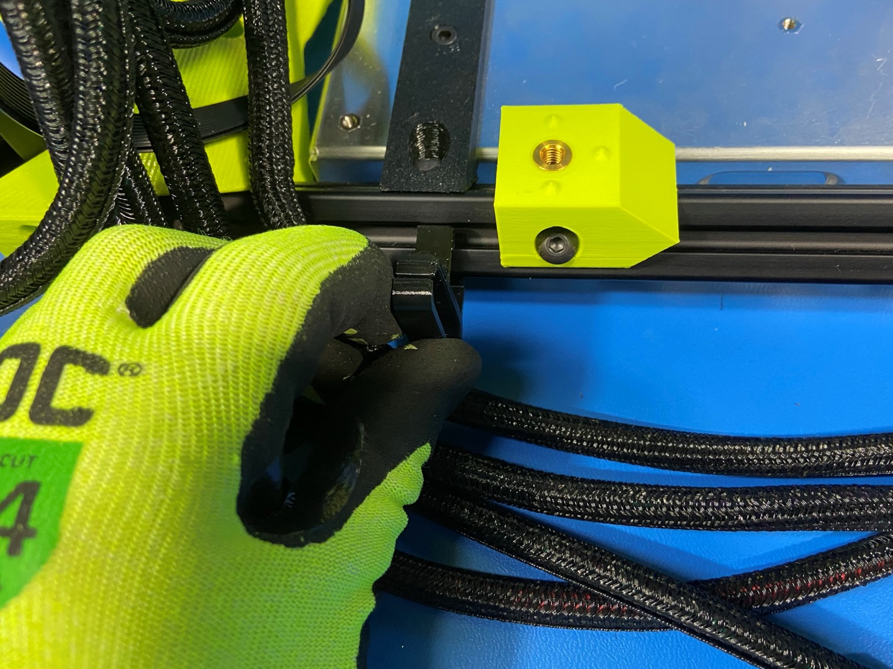
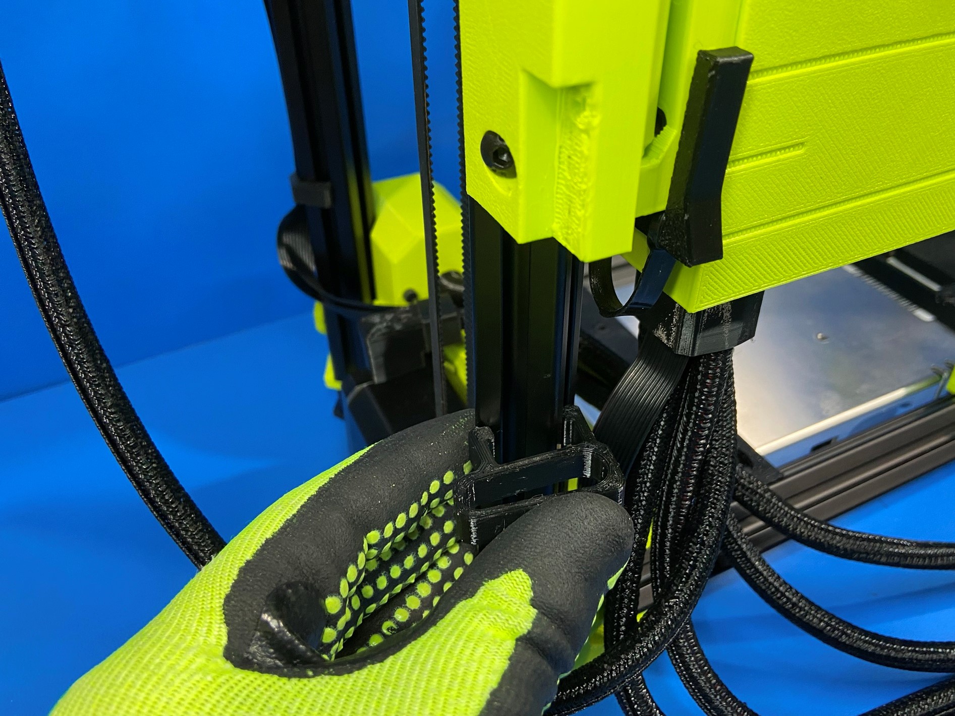
Now take 2x LCD cable clips [PP-GP0658] and place them on the front right extrusion on the outer side.
The bottom clip will have the opening facing the power switch and the top clip will have the facing towards the X motor.
To place these clip take one side and push it in the grove on the extrusion and firmly push the other side into the opposite grove, there should be an audible snap if done correctly. Note: if you didn't hear a noise, check clip to ensure its properly seated on the extrusion
Then take the LCD harnesses and slide them into the openings of each clip.
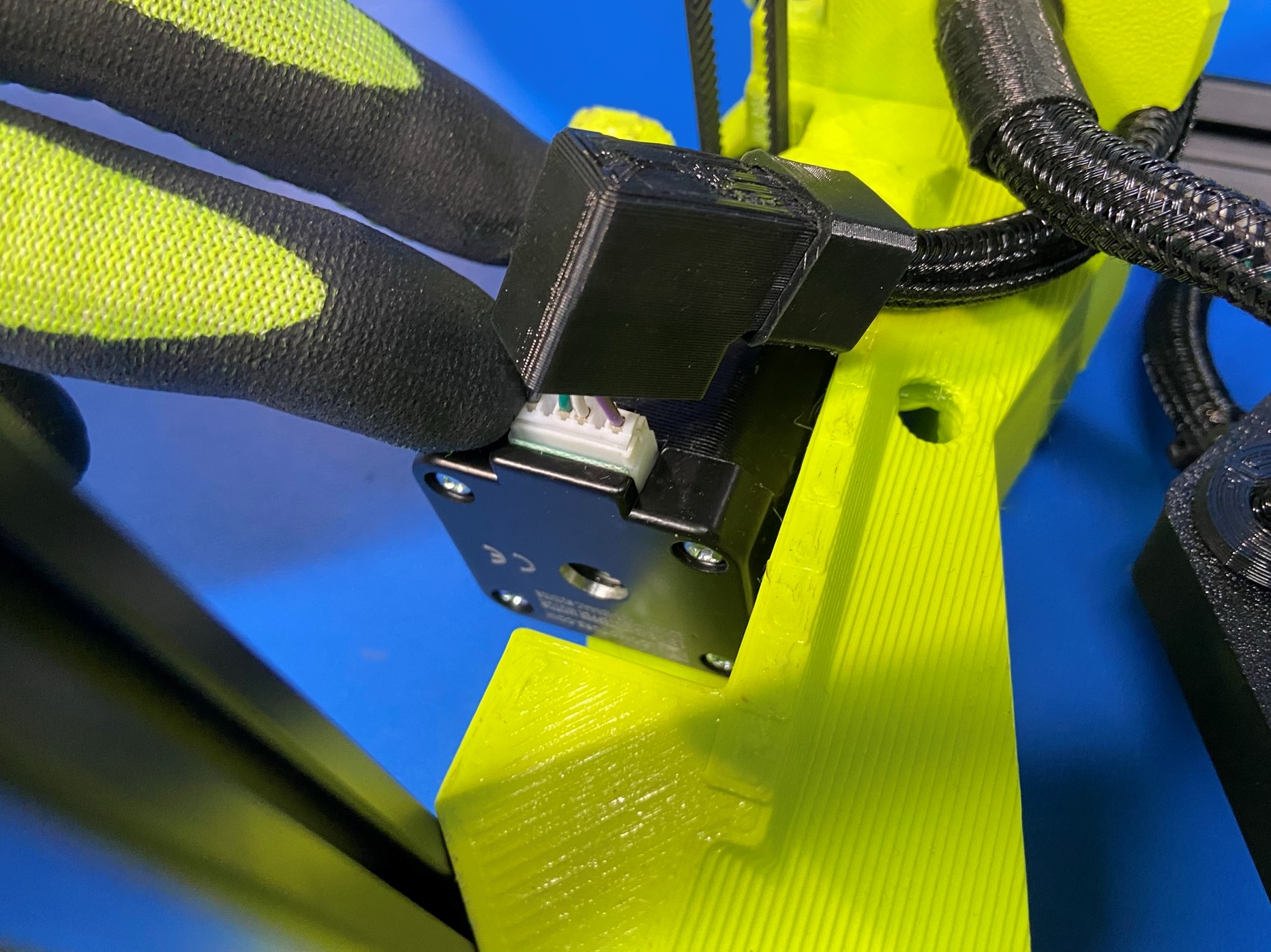
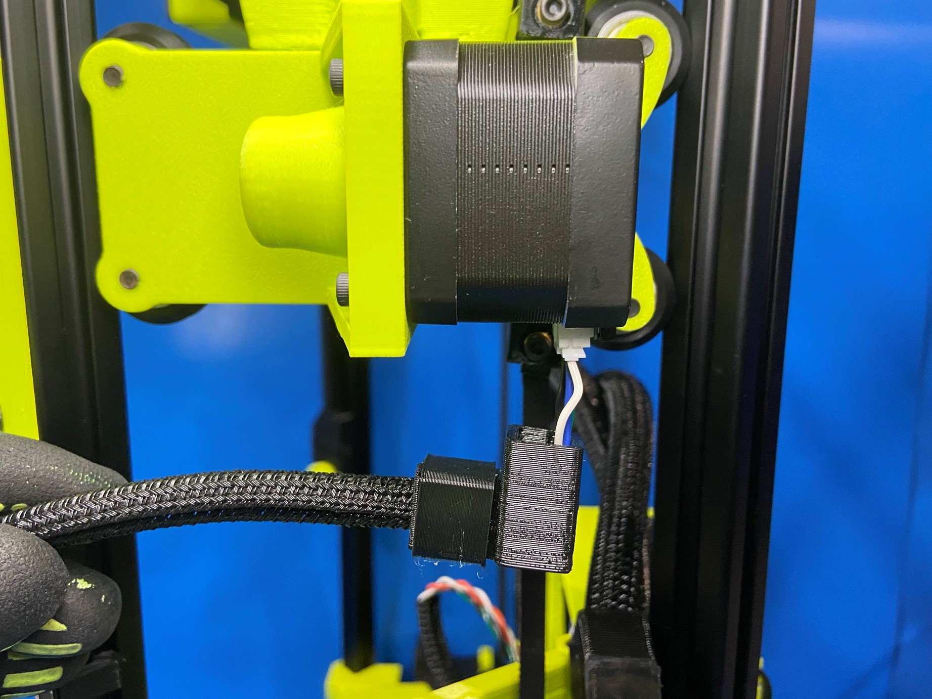
Find the X motor harness, longer harness with blue wire.
Then route the harness on the backside of the extrusion and connect it to the X motor.
Then using the flexy rosebud wrap 1 [PP-GP0578] secure the harness to the X motor mount.
This is done by taking one end of the flexy rosebud and pushing through the hole on the bottom side of the X motor mount.
Note: make sure the flanged side of the rosebud is on the outside.
Then wrap the flexy rosebud around the harness and then push the other side through the same hole.
Pull on the wrap to make sure its secure, then firmly push the harness boot over the motor connector.
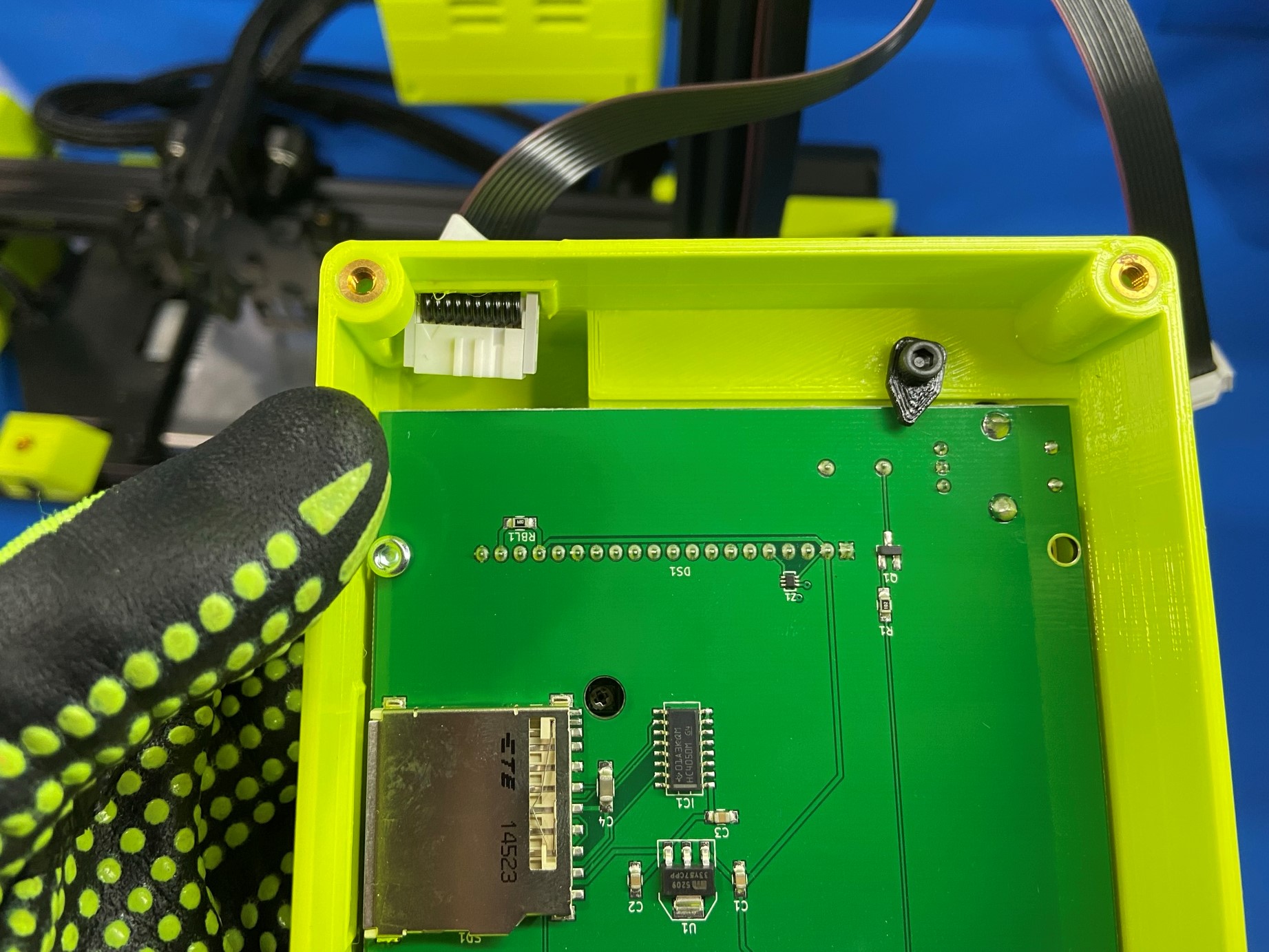
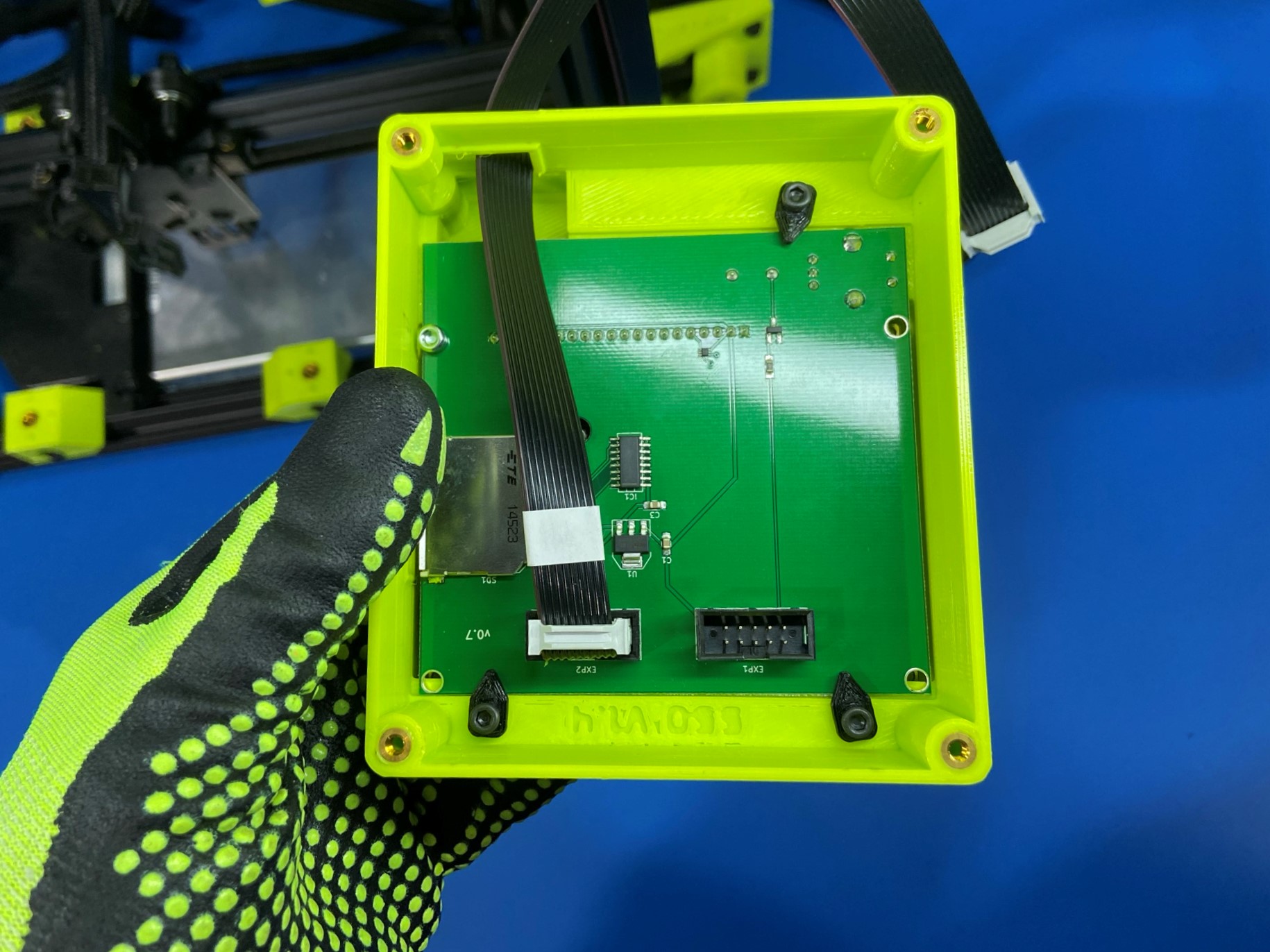
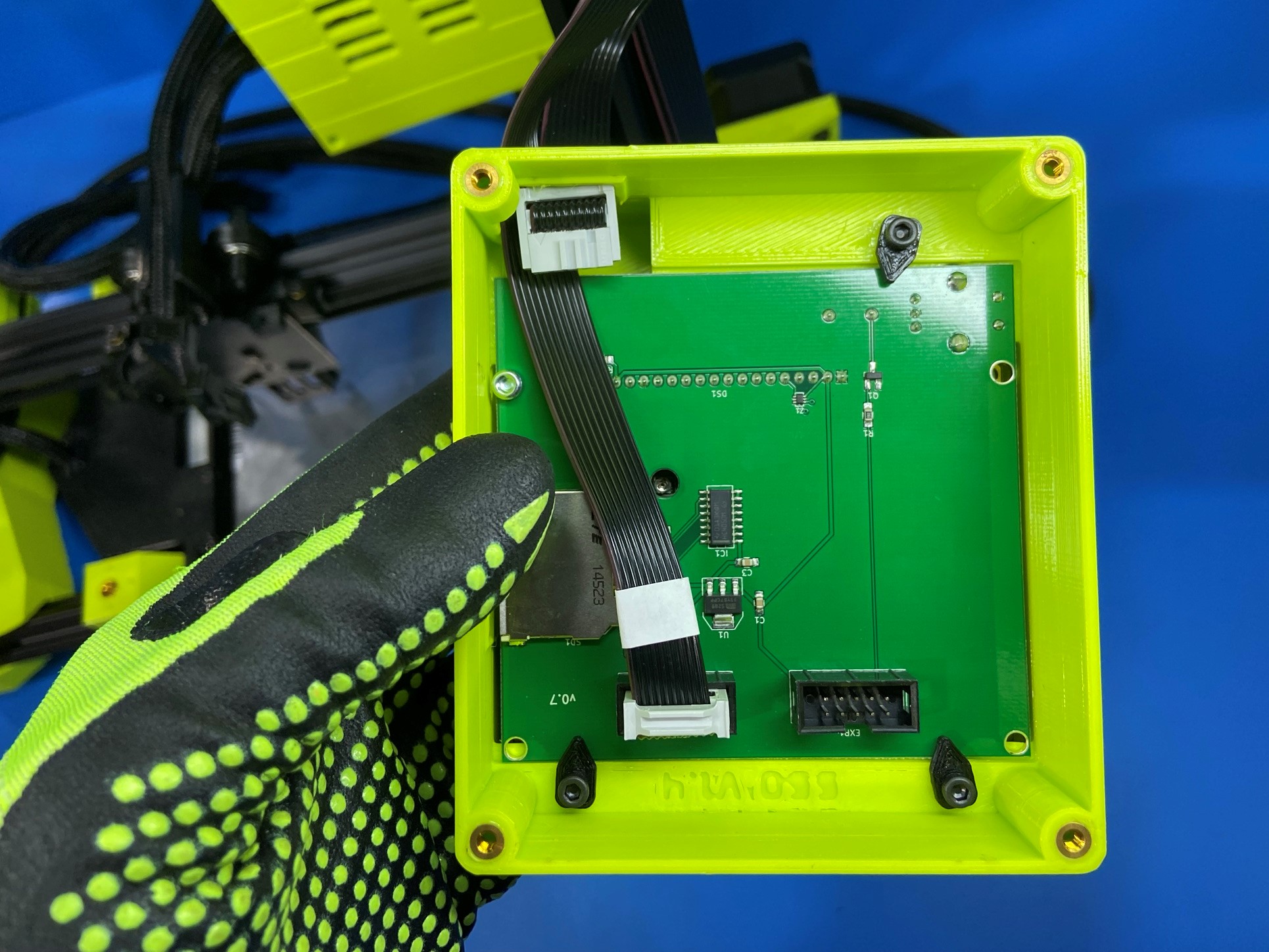
Push the LCD harnesses through the rectangular hole in the LCD case. make sure the tabs are on the top side of the harness.
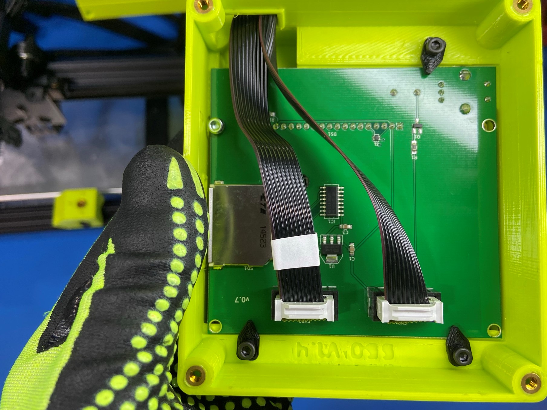
Then connect the LCD harnesses to the LCD, LCD 2 will have a white piece of tape around it.
Connect LCD 2 to the port that has EXP 2 and LCD 1 to the port that has EXP 1.
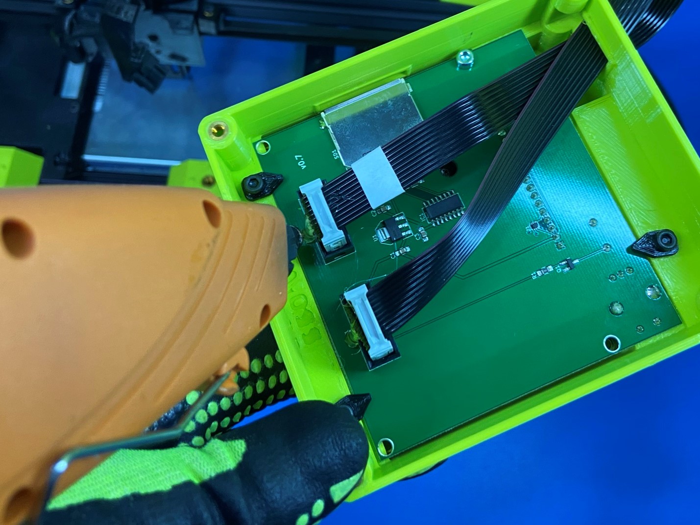
Once the LCD harnesses are connected use the hot glue gun and place hot glue over the tabs, securing the connection.
Then use 4x M3x6 FHCS [HD-BT0128] to install the LCD case to the LCD backplate.
Check the LCD harnesses making sure they are pulled to tight when the LCD is in closed position.
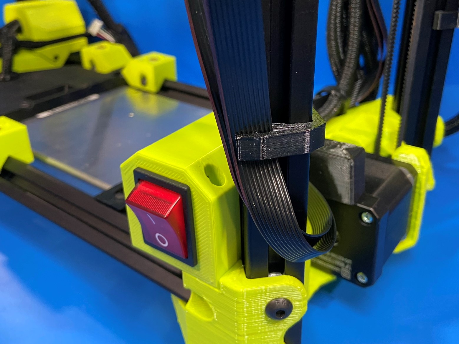
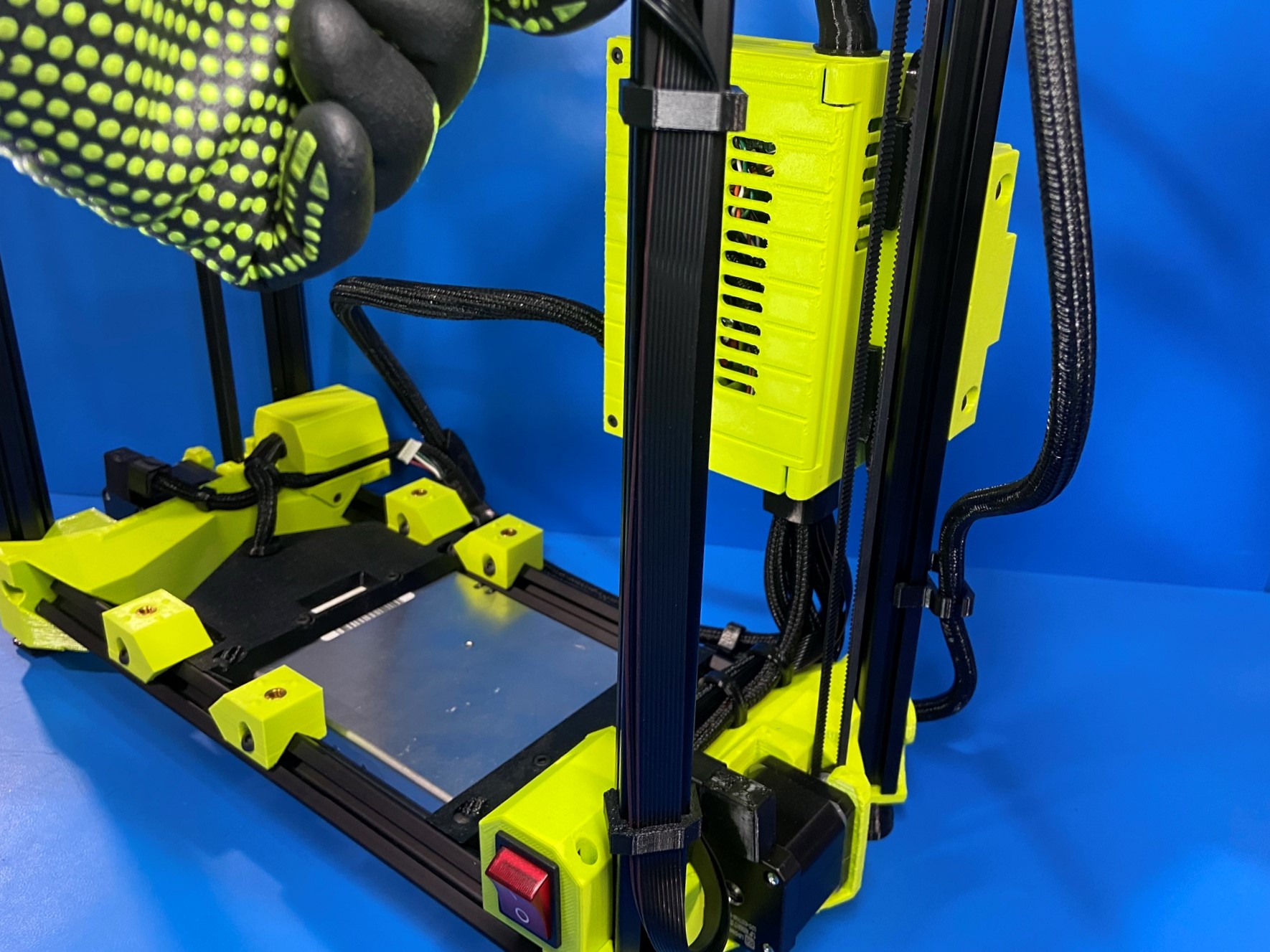
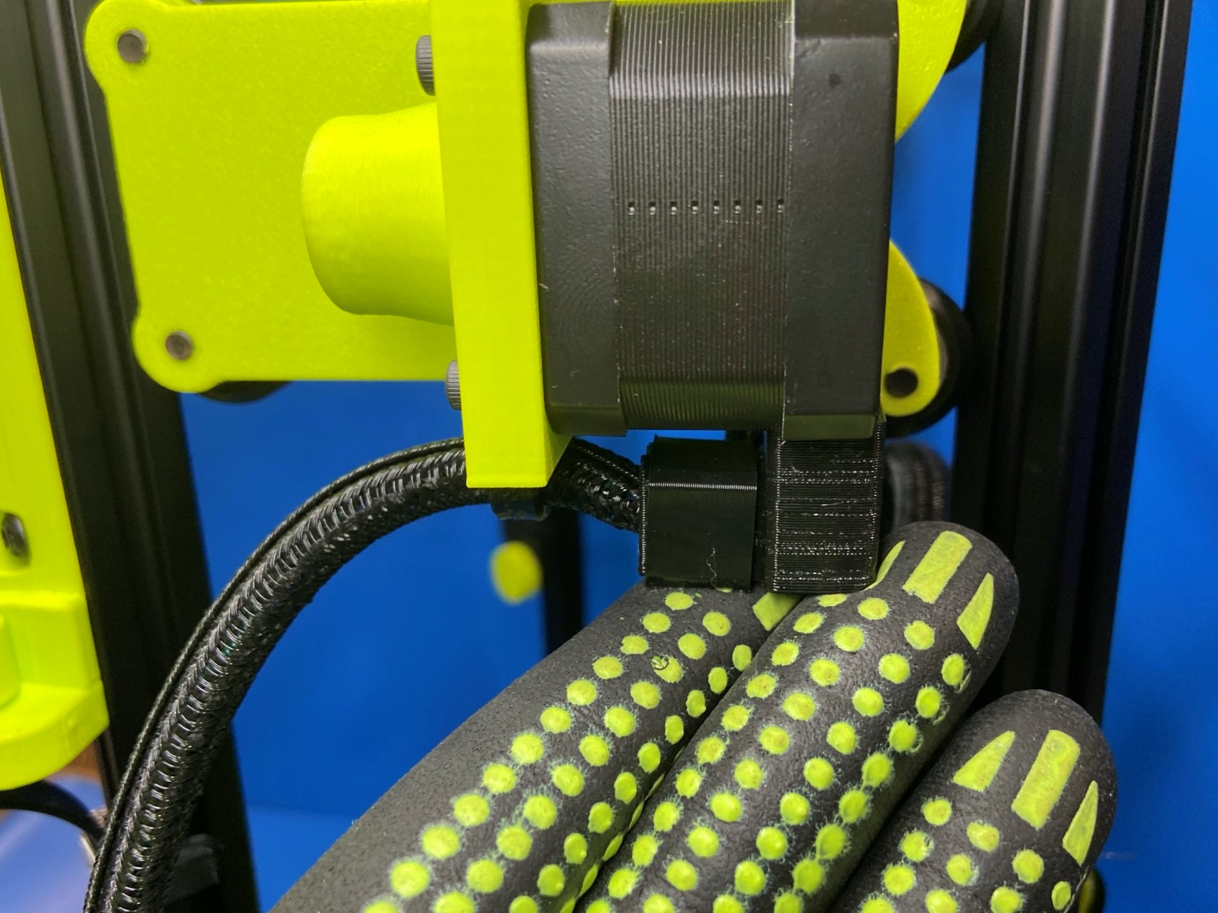
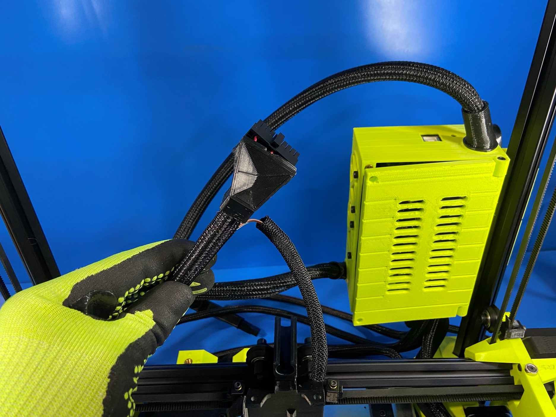
Find the extruder harness, it will be the harness that comes through the top of the control box.
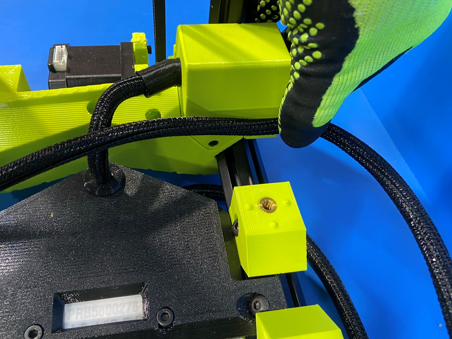
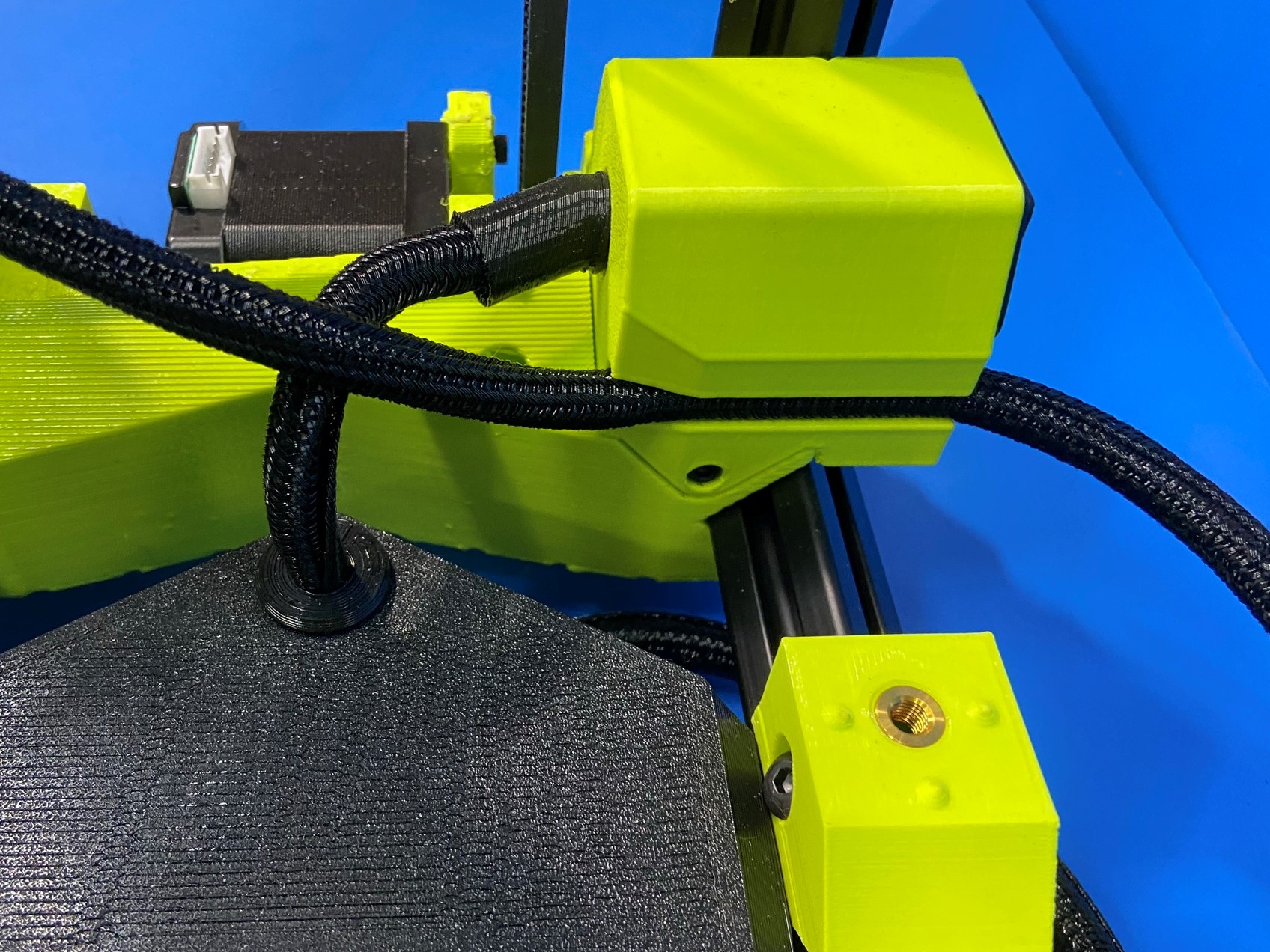
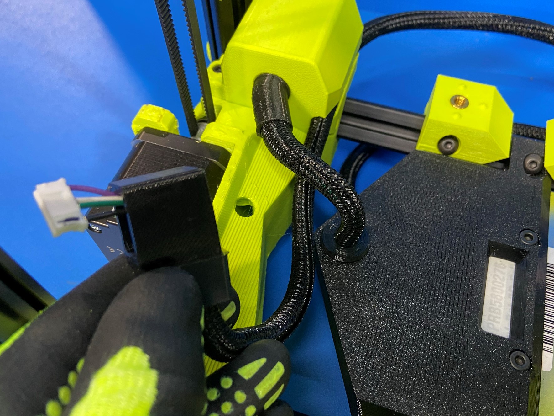
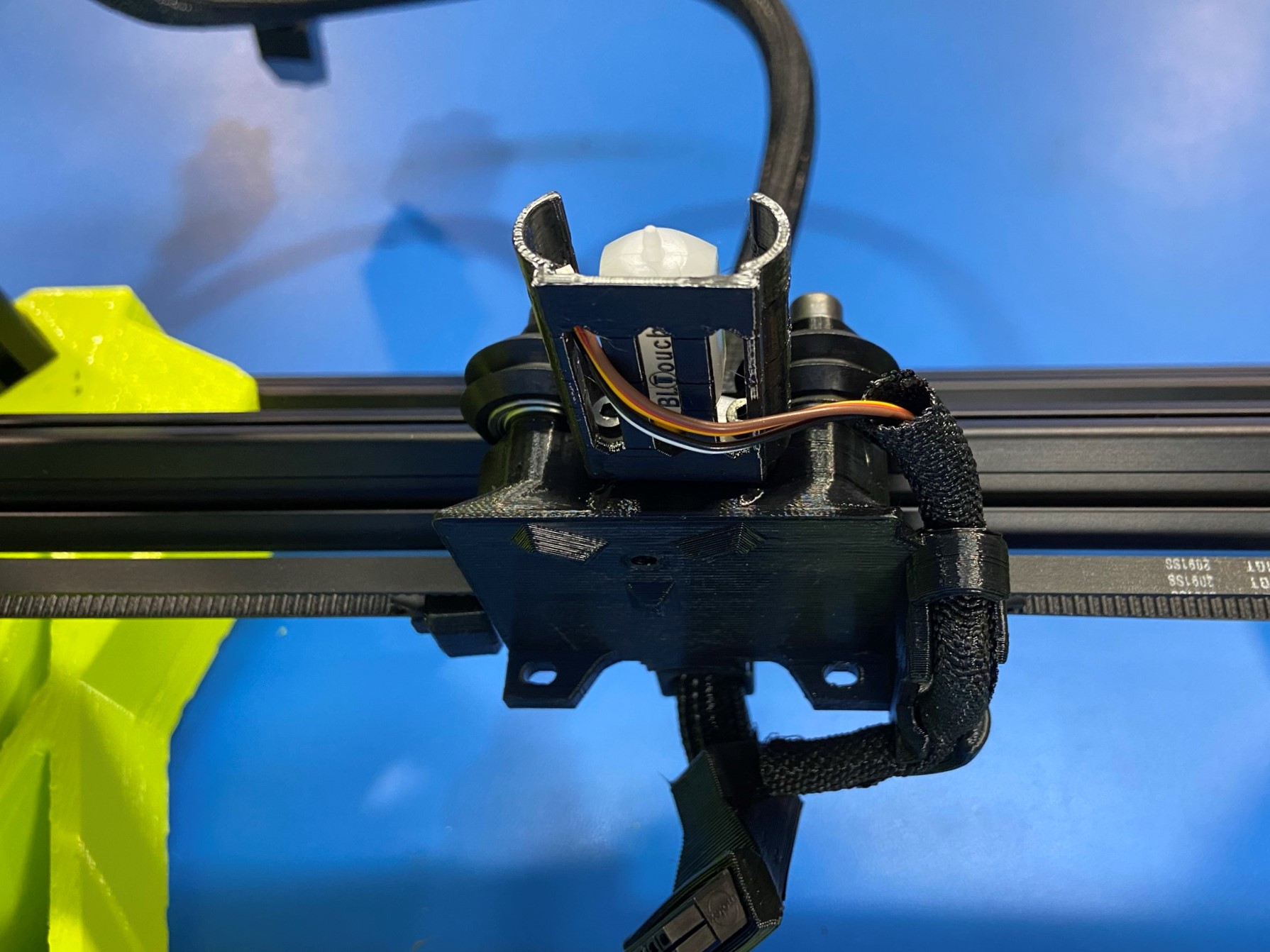
Then take the harness and route it through the strain relief that is on the top of the X carriage.
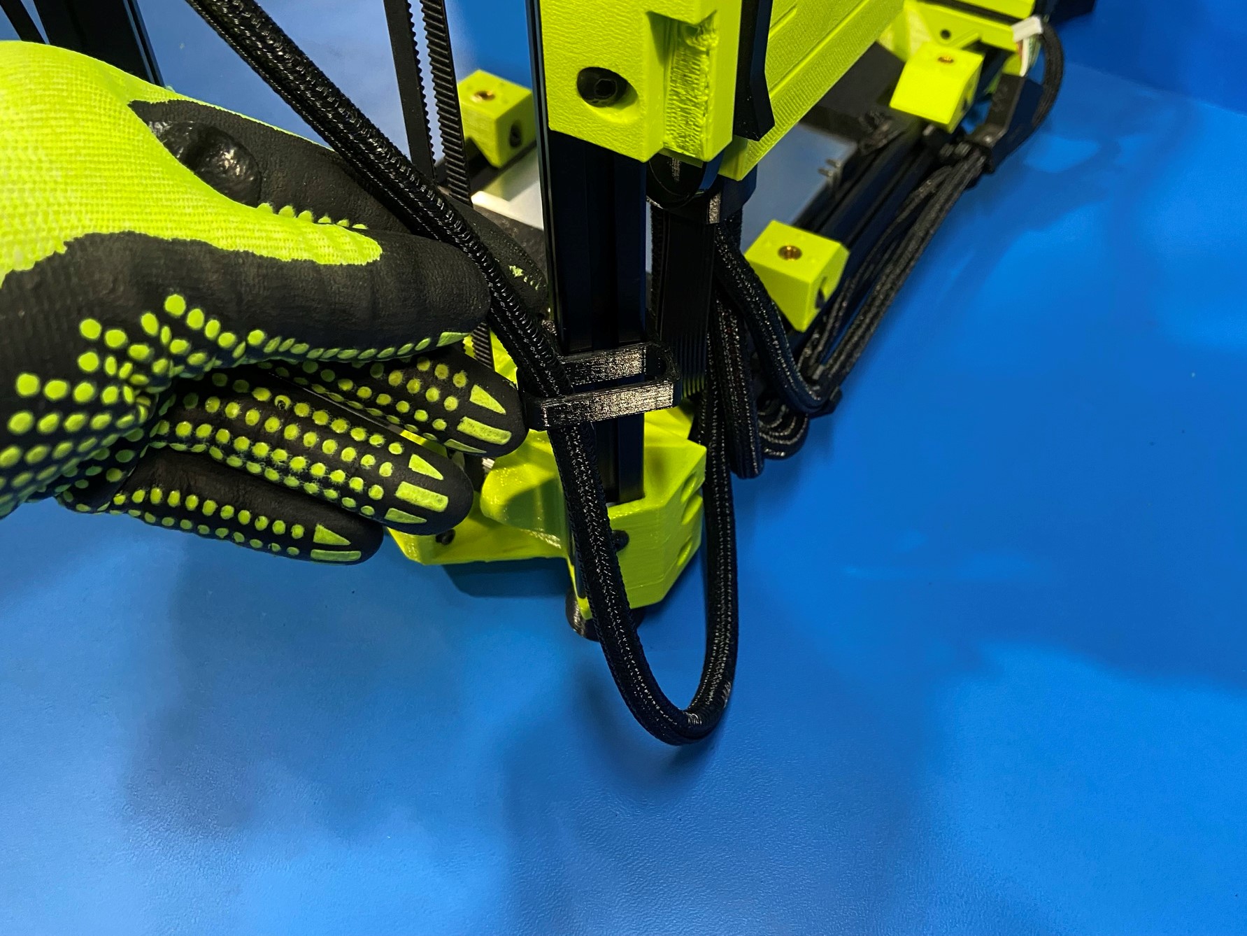
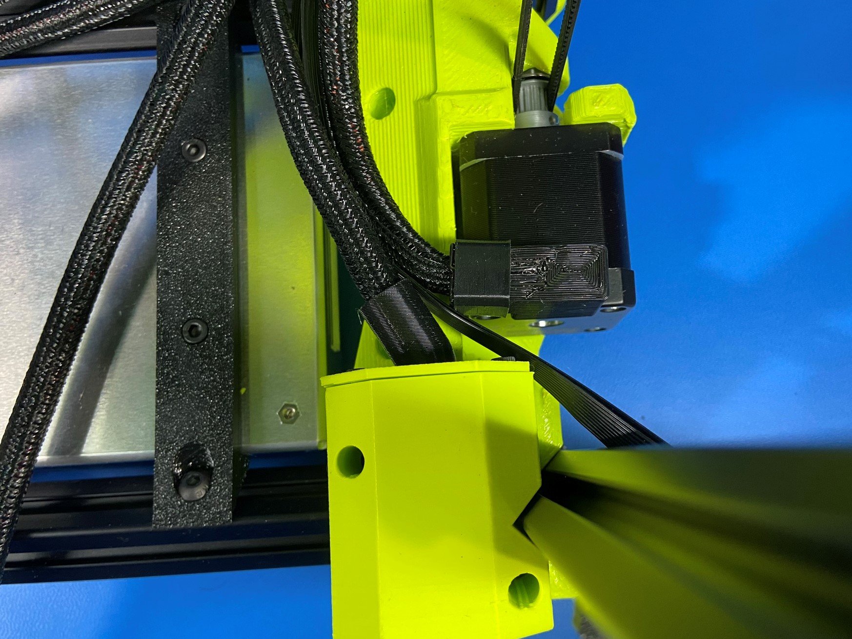
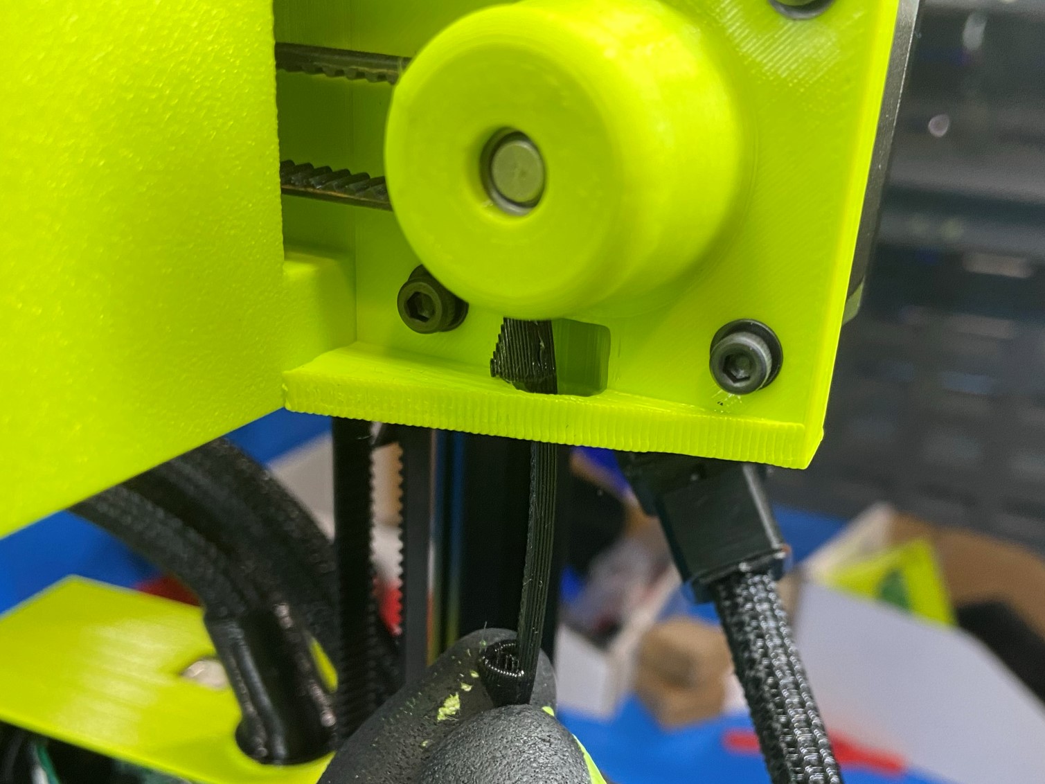
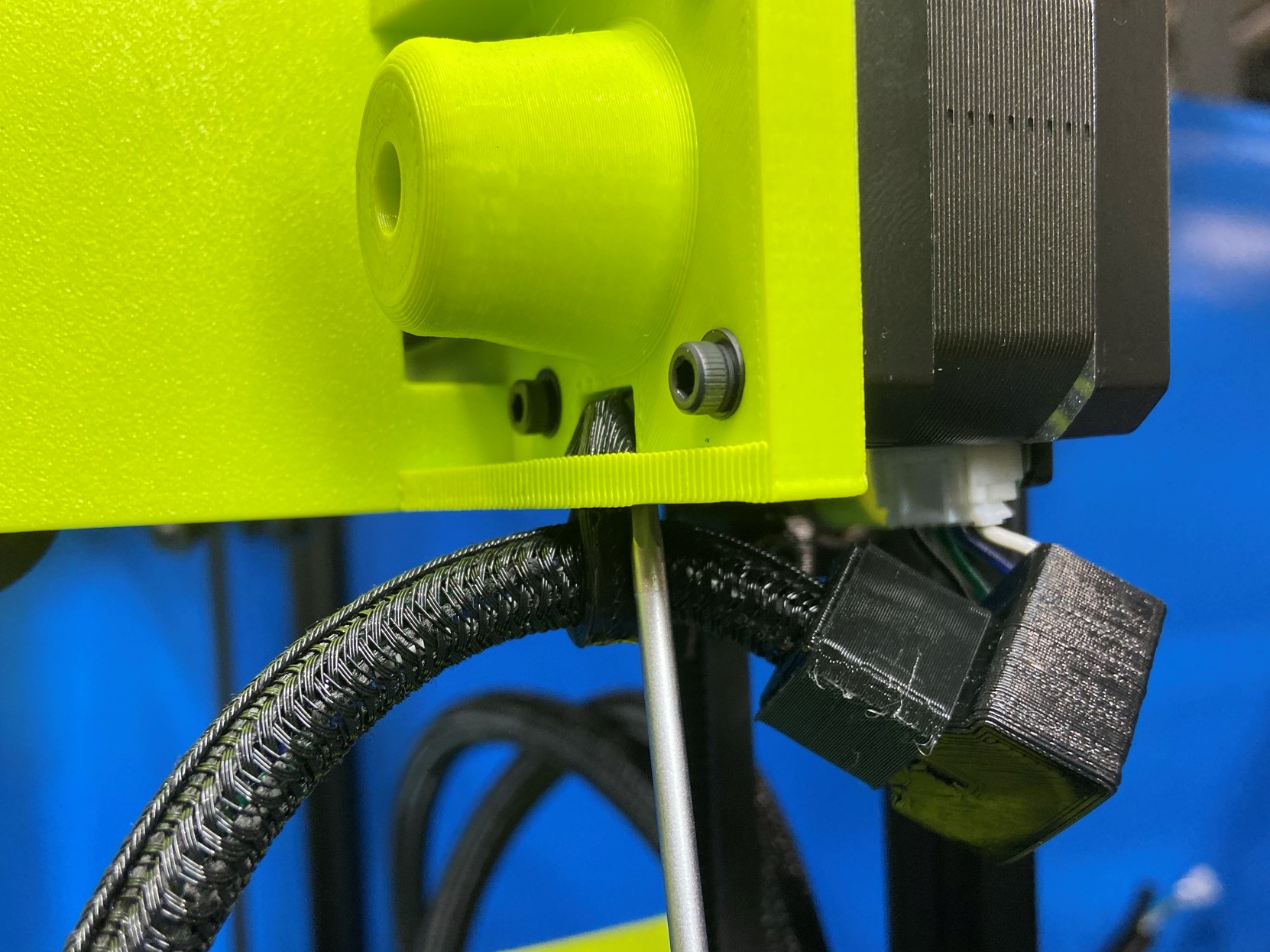
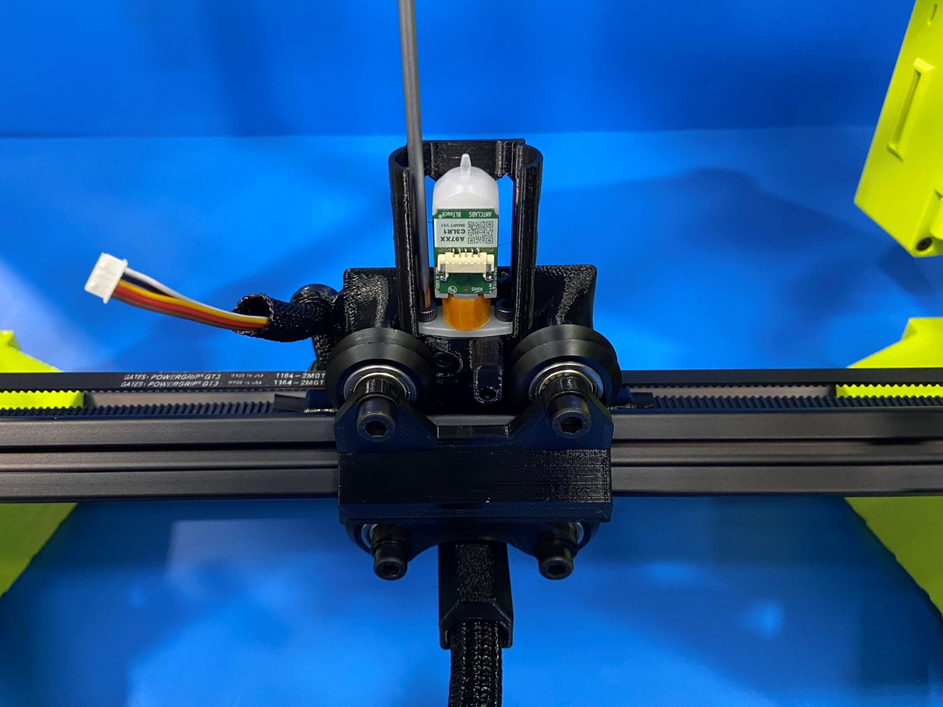
Now take the BLTouch wire (smaller wires that branch off of the extruder harness) and route it through the two curved channels on the left side of the printer. As shown in [reference#2]
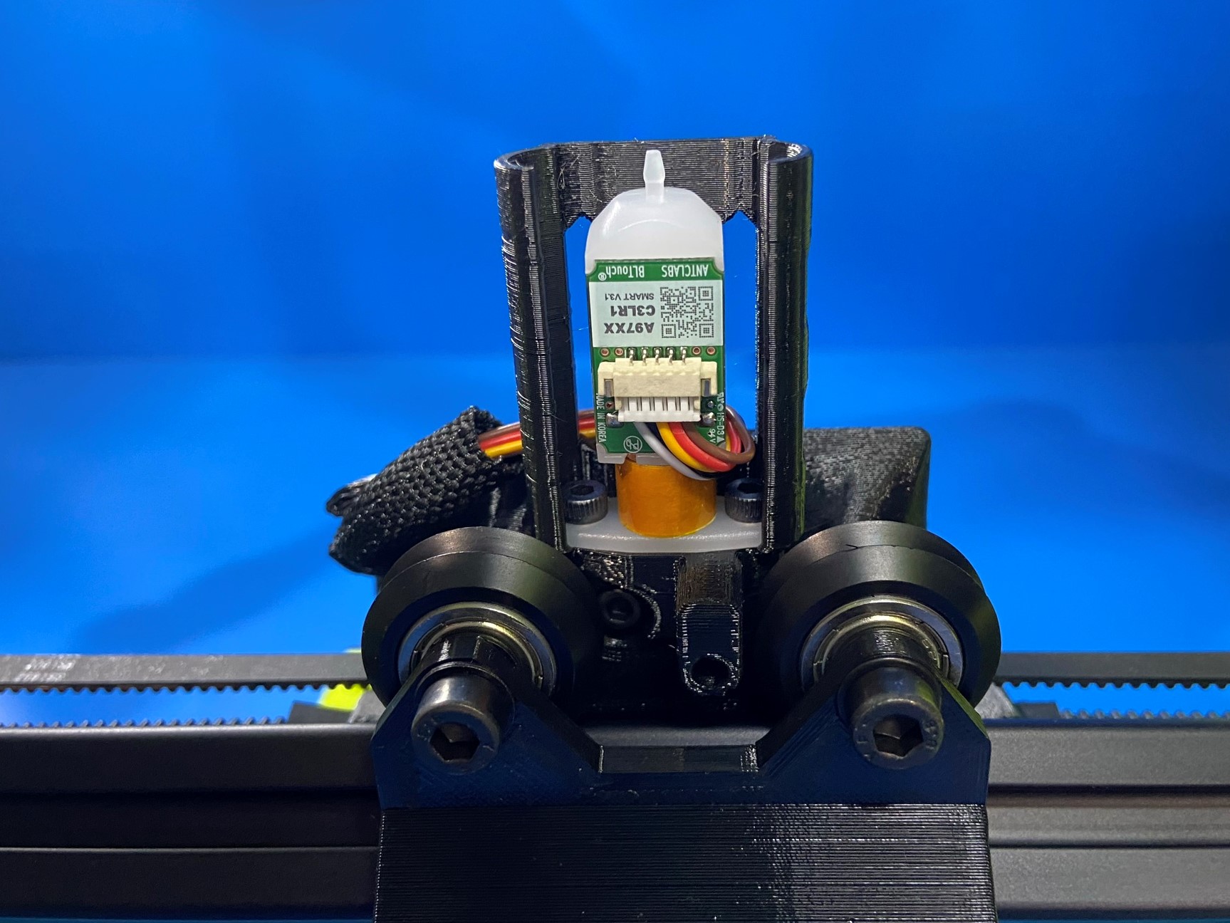
Mount the BLTouch [PP-MP0327] to the BLTouch mount on the X carriage, using 2x M3x8 SHCS [HD-BT0045]. It may help to flip the printer over to have better access to the bottom side of the X carriage.
Then route the wire through the BLTouch mount cage and connect it to the BLTouch.
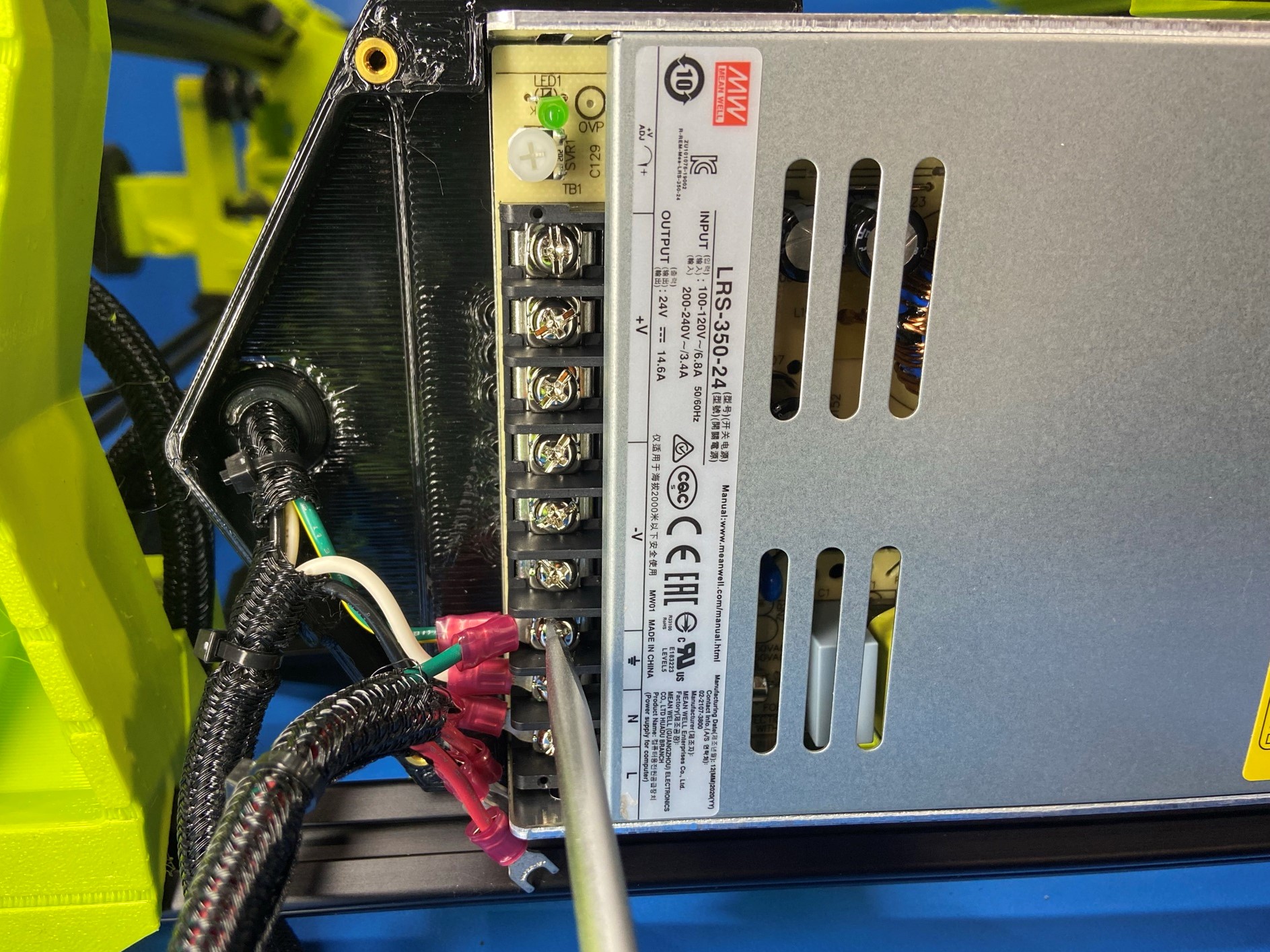
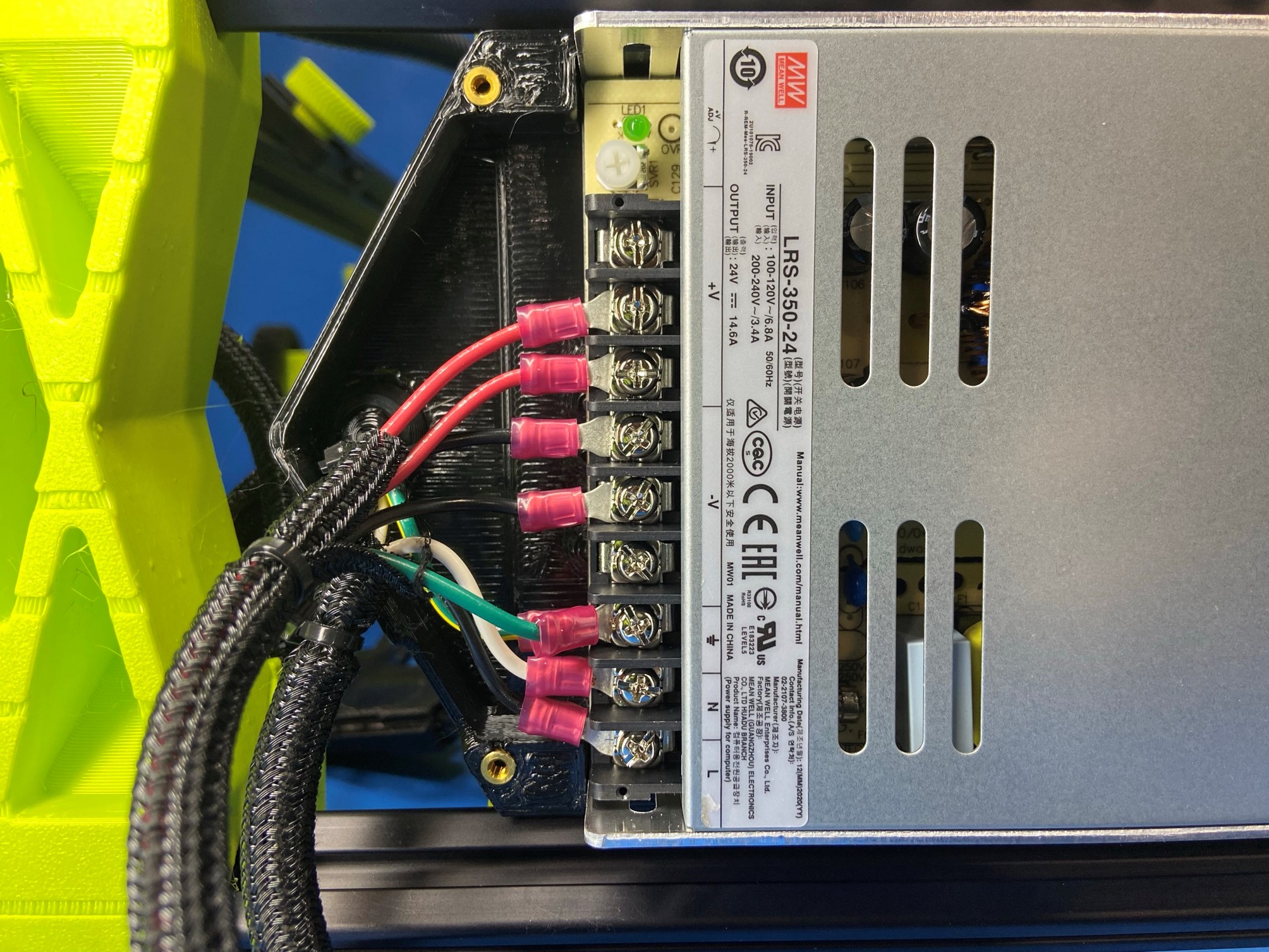
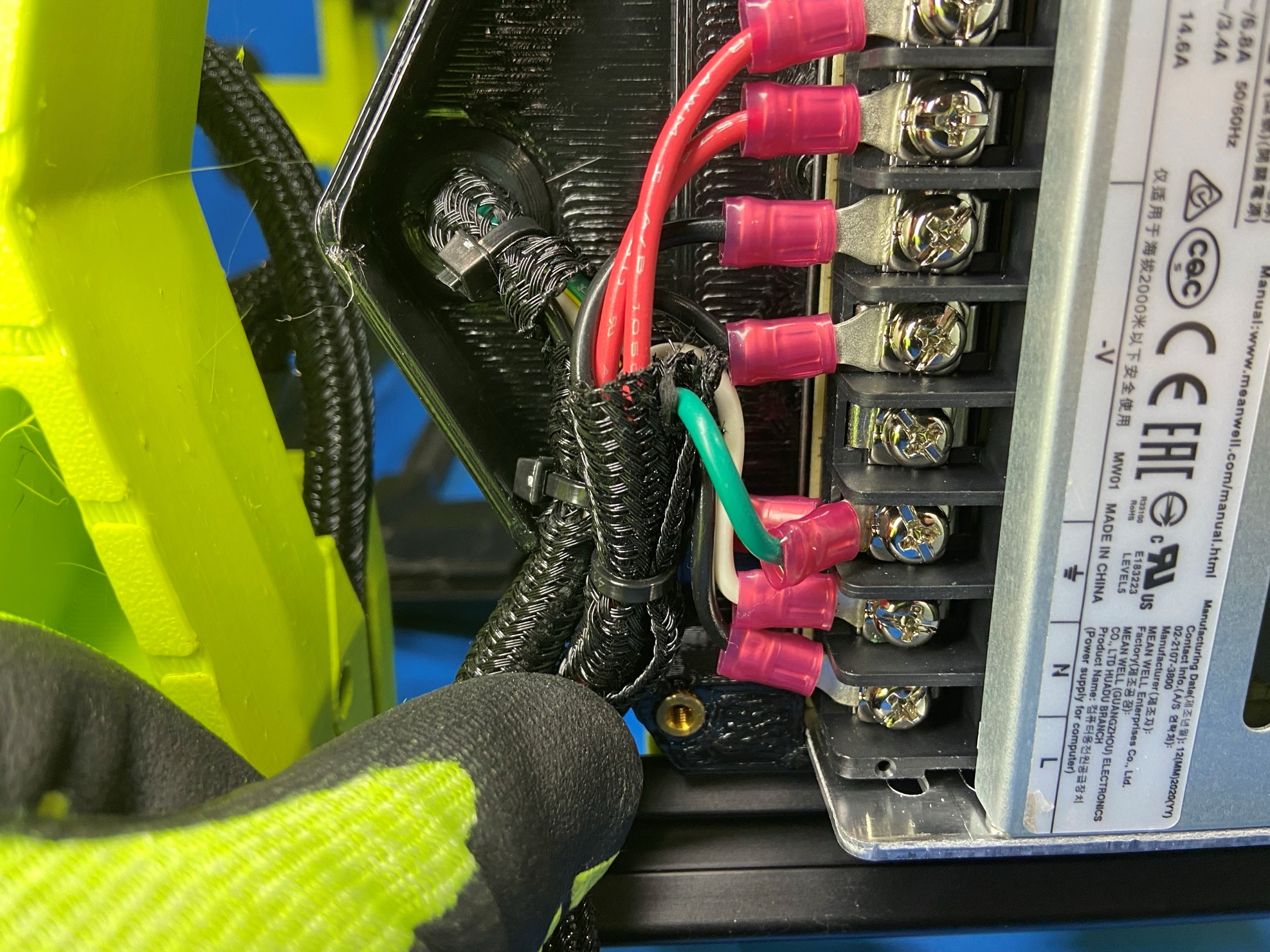
Flip the printer over so that the bottom of the printer is facing up, then find the harness that has 5 spade connectors (power supply to board harness).
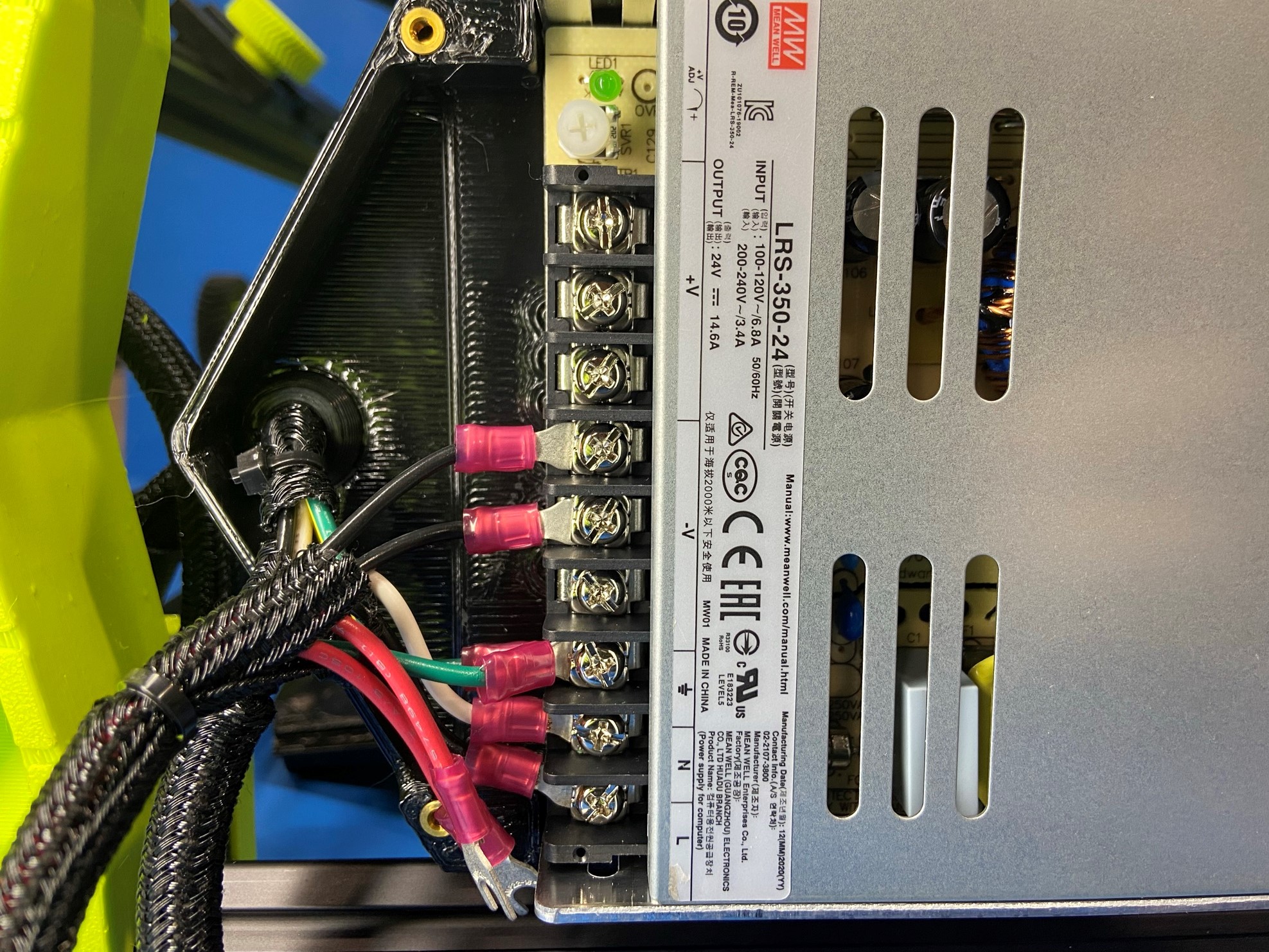
Loosen the ground terminal then place the green ground wire under the screw and tighten.
Then skip one screw and loosen the next two and slide the two black wires under the two terminals. Tighten both screw to secure the wires.
Now loosen the next two terminals and slide the two red wires under the terminals, then tighten these two screws, leaving the last terminal empty.
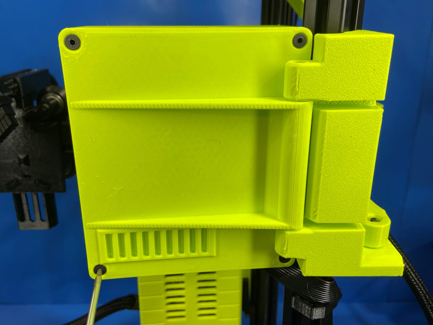
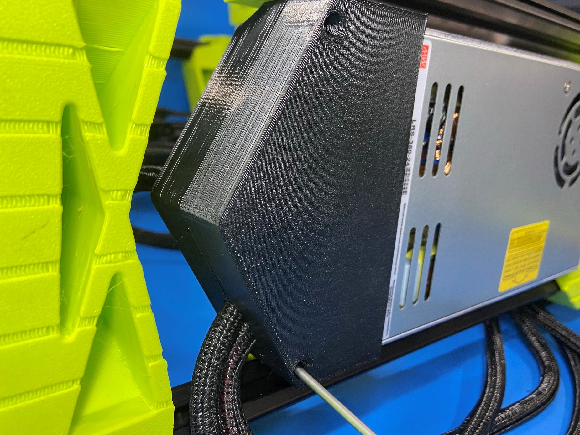
Then route the both harnesses through the cut out as shown in [reference#1].
Using 2x M3x10 SHCS [HD-BT0005] cover the power supply with the 747 power supply bottom [PP-GP0604].
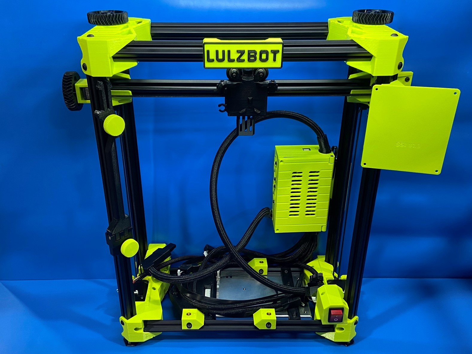
Then flip printer back over, so the bottom of the printer is resting on the table.

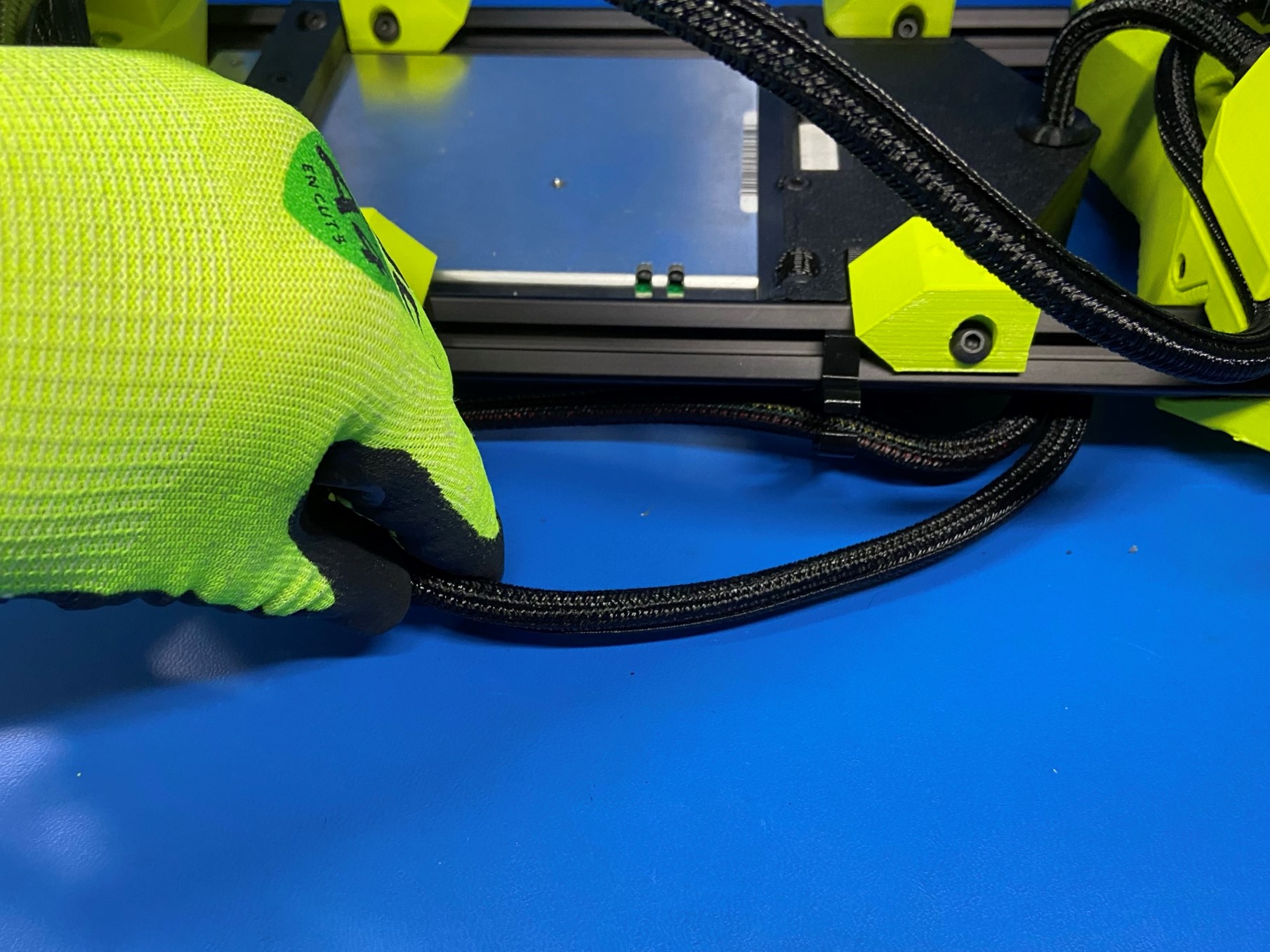
Use the same process as the LCD clips for placing the cable clips, make sure the openings are facing up for the bottom extrusion and opening away from the control box for the side extrusion.
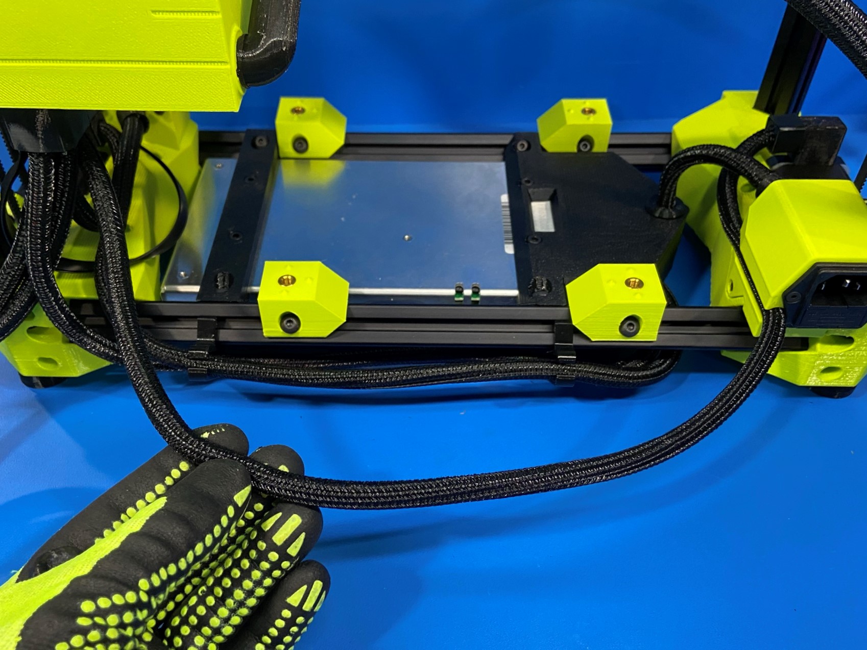
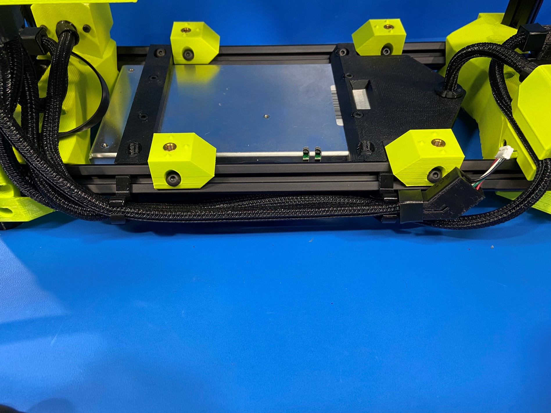
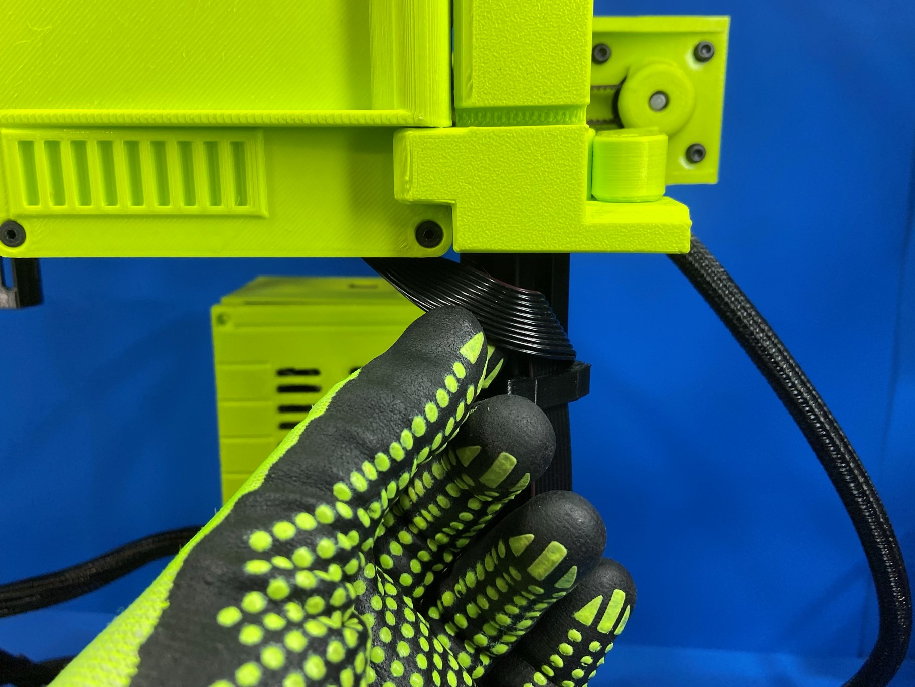
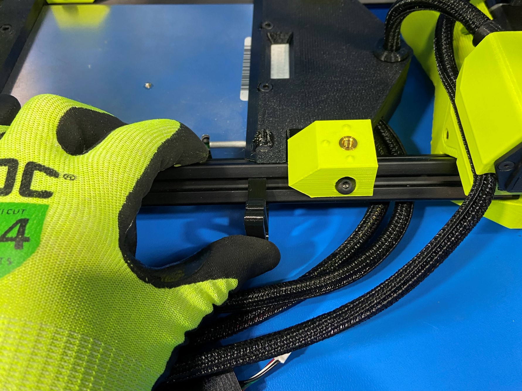
Take 2x 3 bundle cable clips [PP-GP0566] and place one on the bottom extrusion on the back side by the power plug and the other one under the control box.
Then take 1x 4 bundle cable clip [PP-GP0679] and place it on the bottom extrusion on the back side on the control box side.
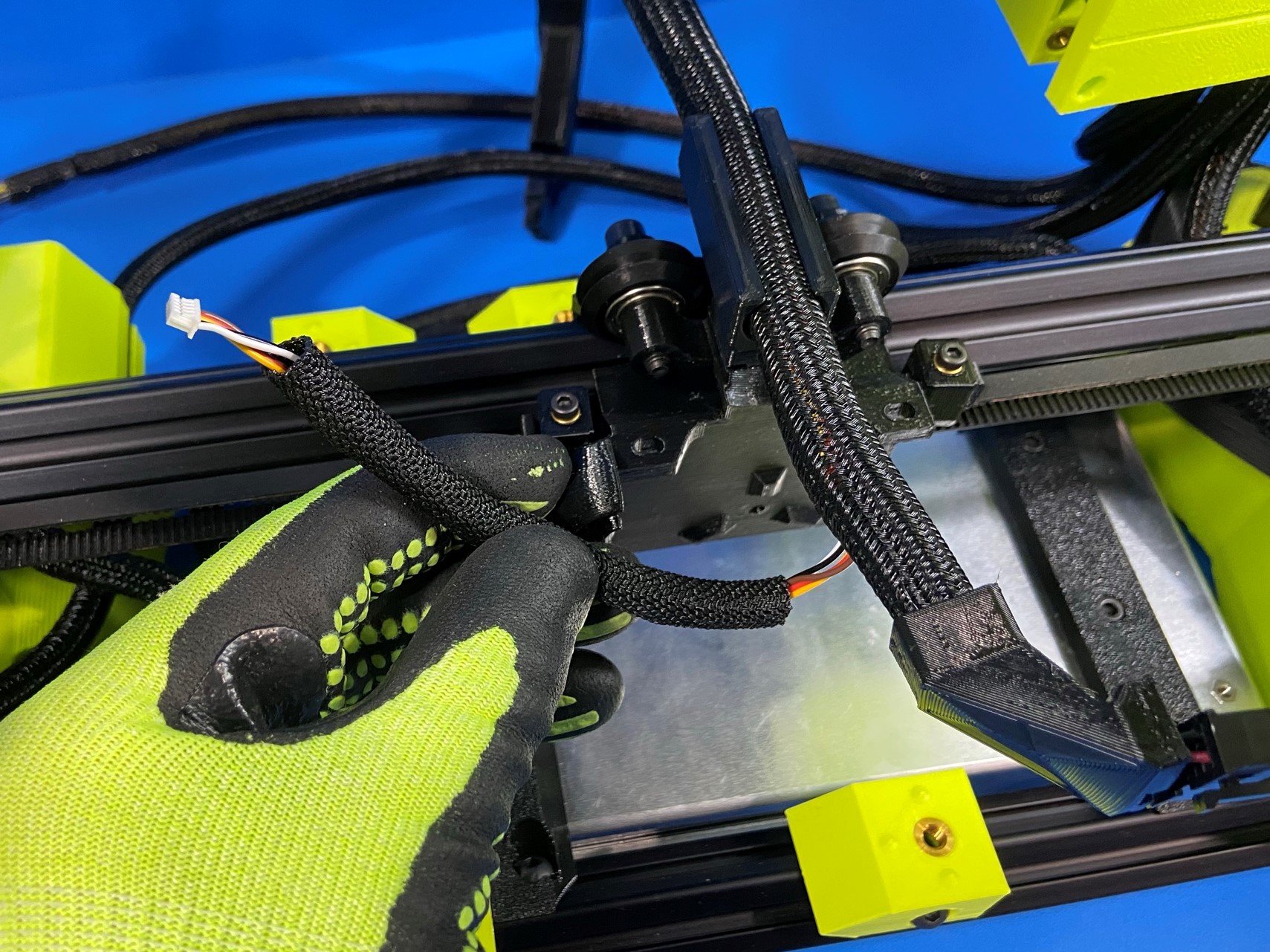
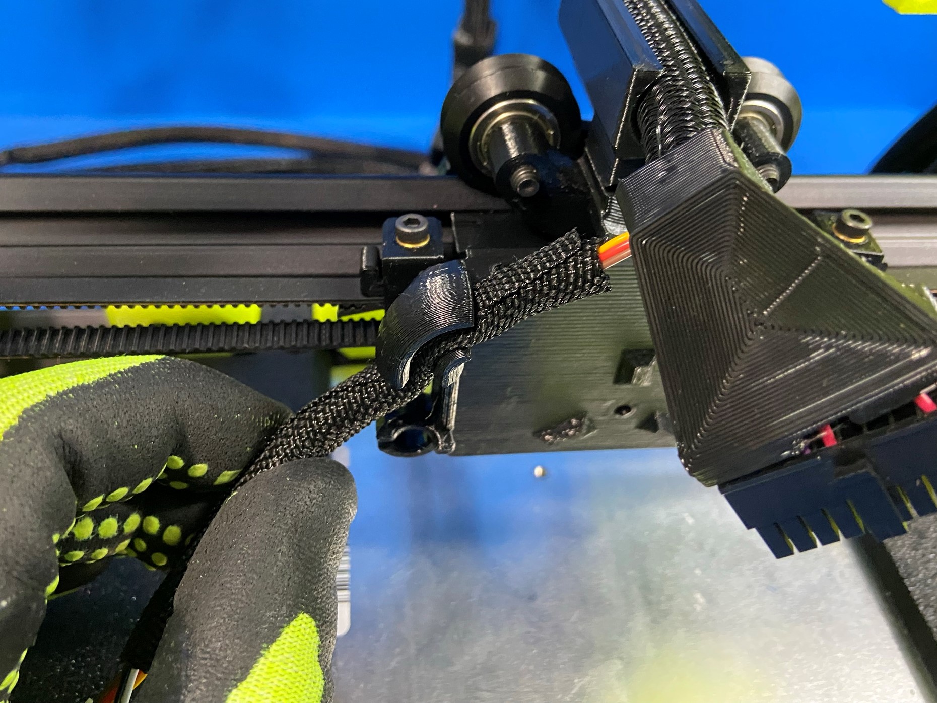
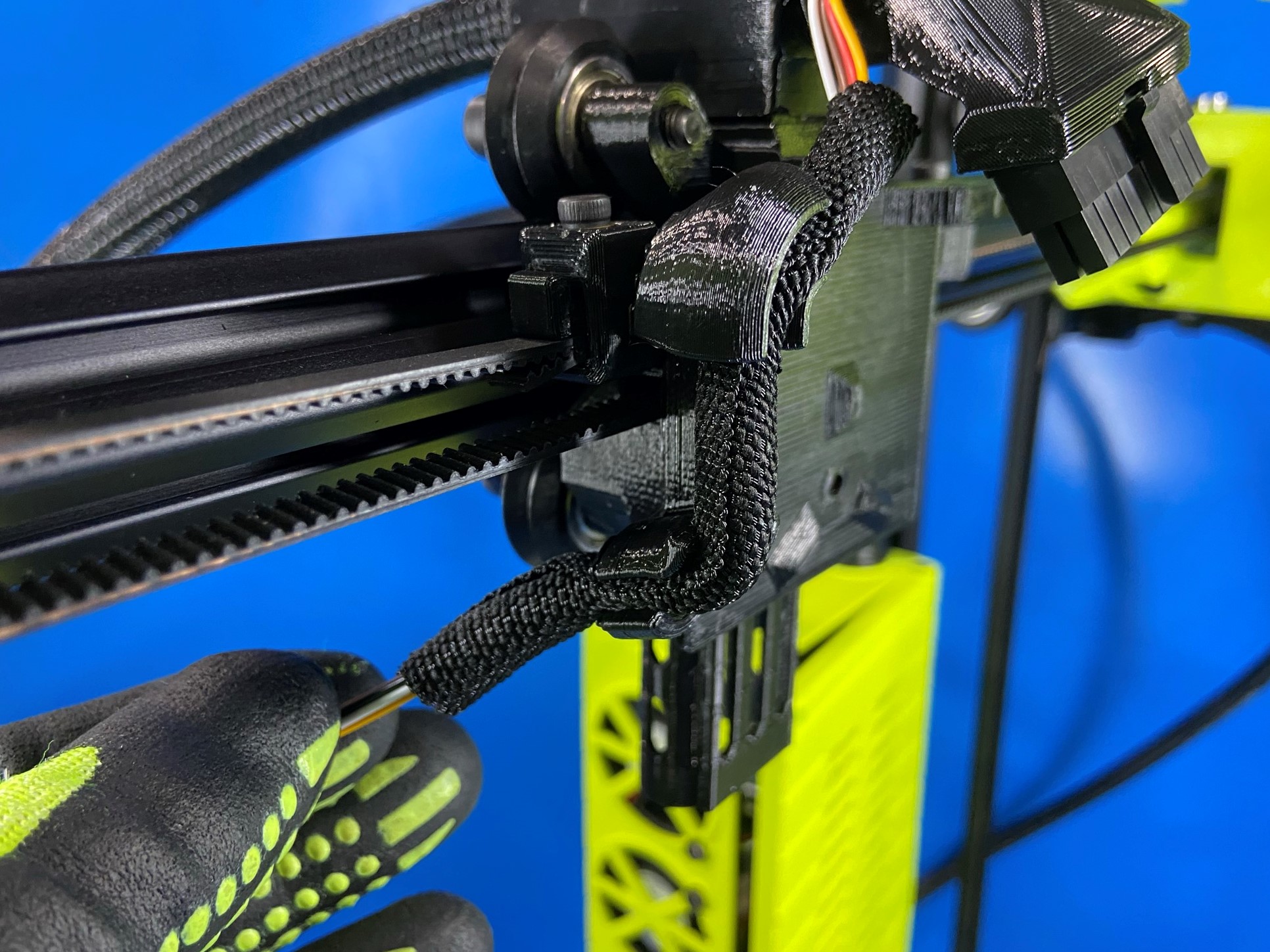
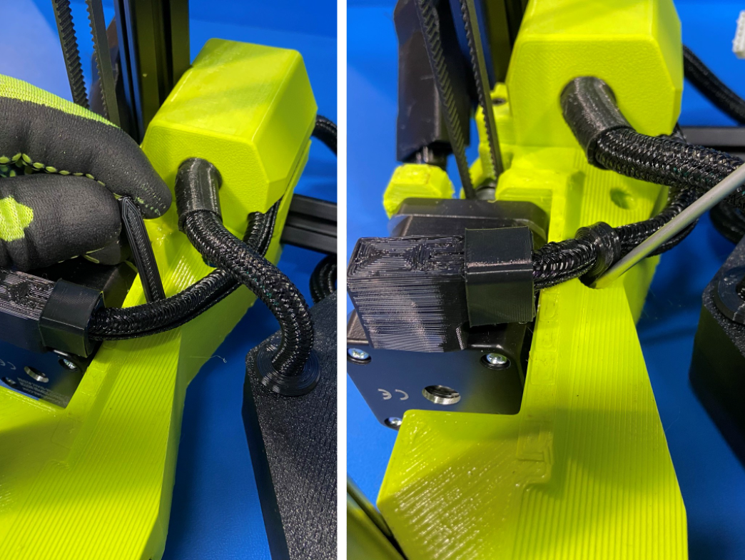
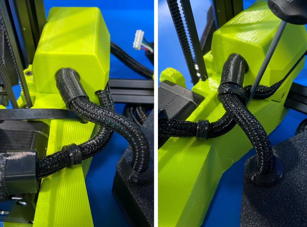
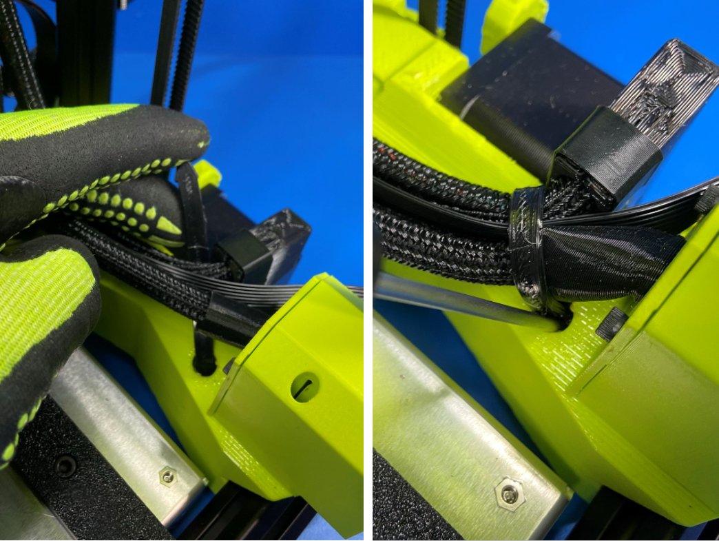
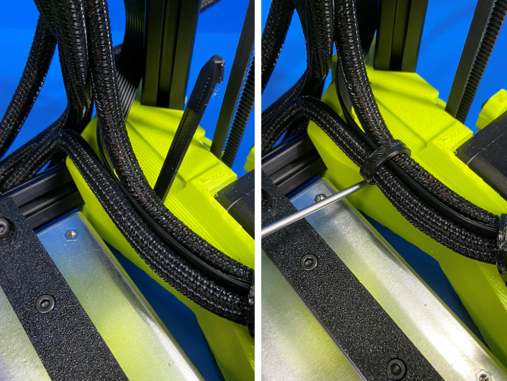
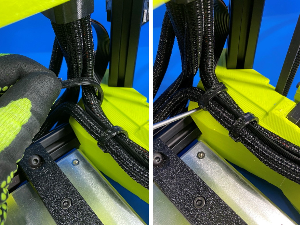
Use 1x flexy rosebud wrap 1 [PP-GP0578] and 4x flexy rosebud wrap 2 [PP-GP0579] for this next step.
To install the rosebud wraps on the printer you will first slide one end of the wrap inside the hole with the flat side facing the harnesses, then wrap it around the harnesses and using a screwdriver push the other end inside the same hole to create a secured fitting around the harnesses.
Follow the pictures for placement.
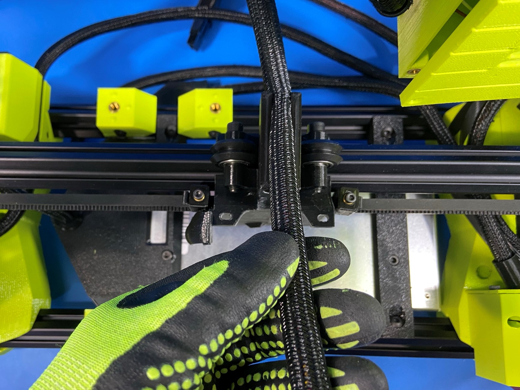
Starting with the 2 cable clips on the backside of the printer, place the power supply to board harness inside the two clips.
Next take the power supply to switch harness and place it inside both clips.
Now take the LZ motor harness and place it inside the clips, then take the Y axis harness and place it inside the clips.
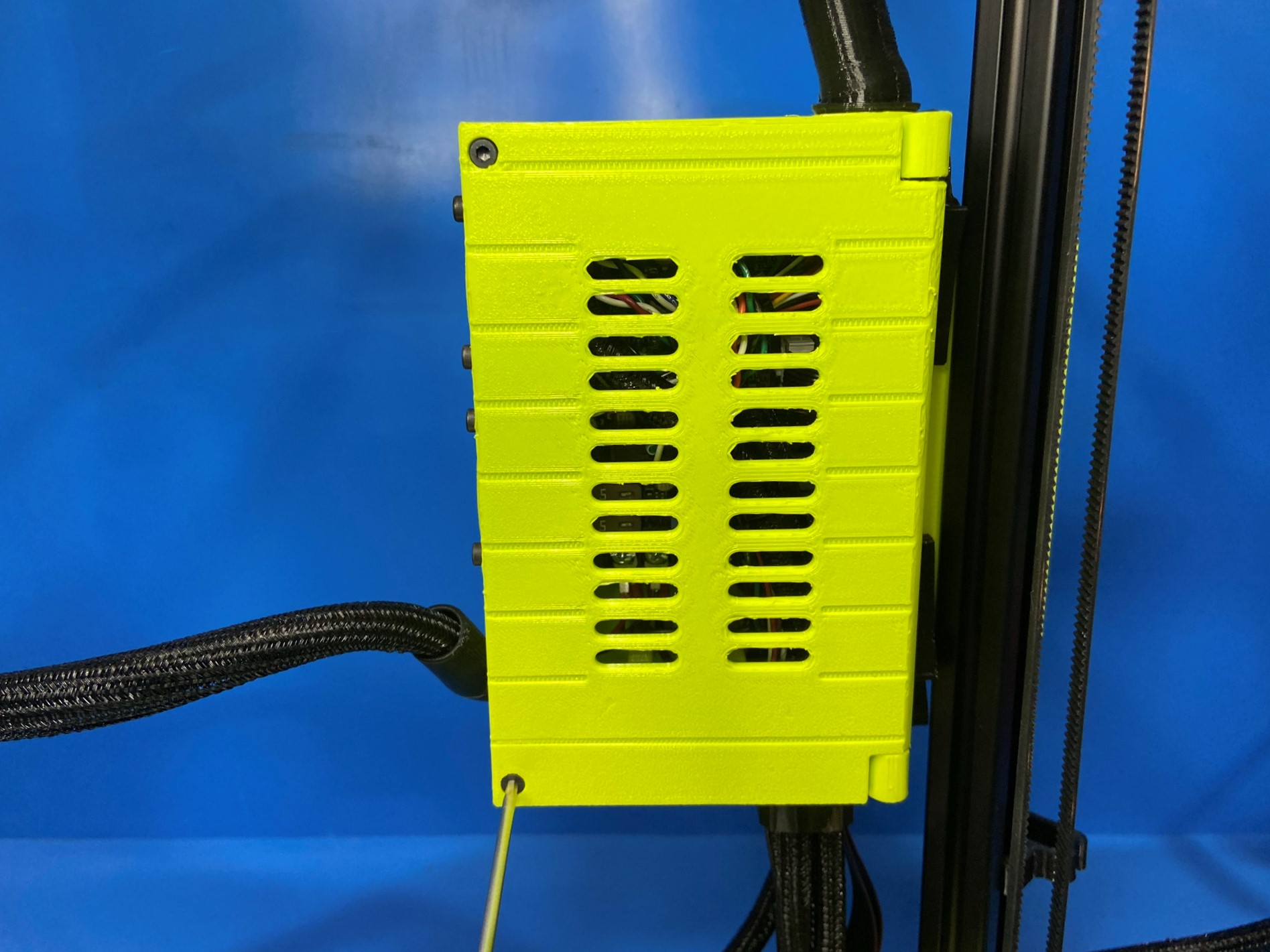
Next take the X axis harness and place it inside the clip on the back right side of the printer, make sure the harness loops down from the control box and then up through the cable clip.
Then using 2x M3x8 SHCS close the control box cover and secure to the control box case.