Open HardwareAssembly Instructions
Guides for installation and assembly of the LulzBot line of products made by FAME 3D LLC.
Guides for installation and assembly of the LulzBot line of products made by FAME 3D LLC.
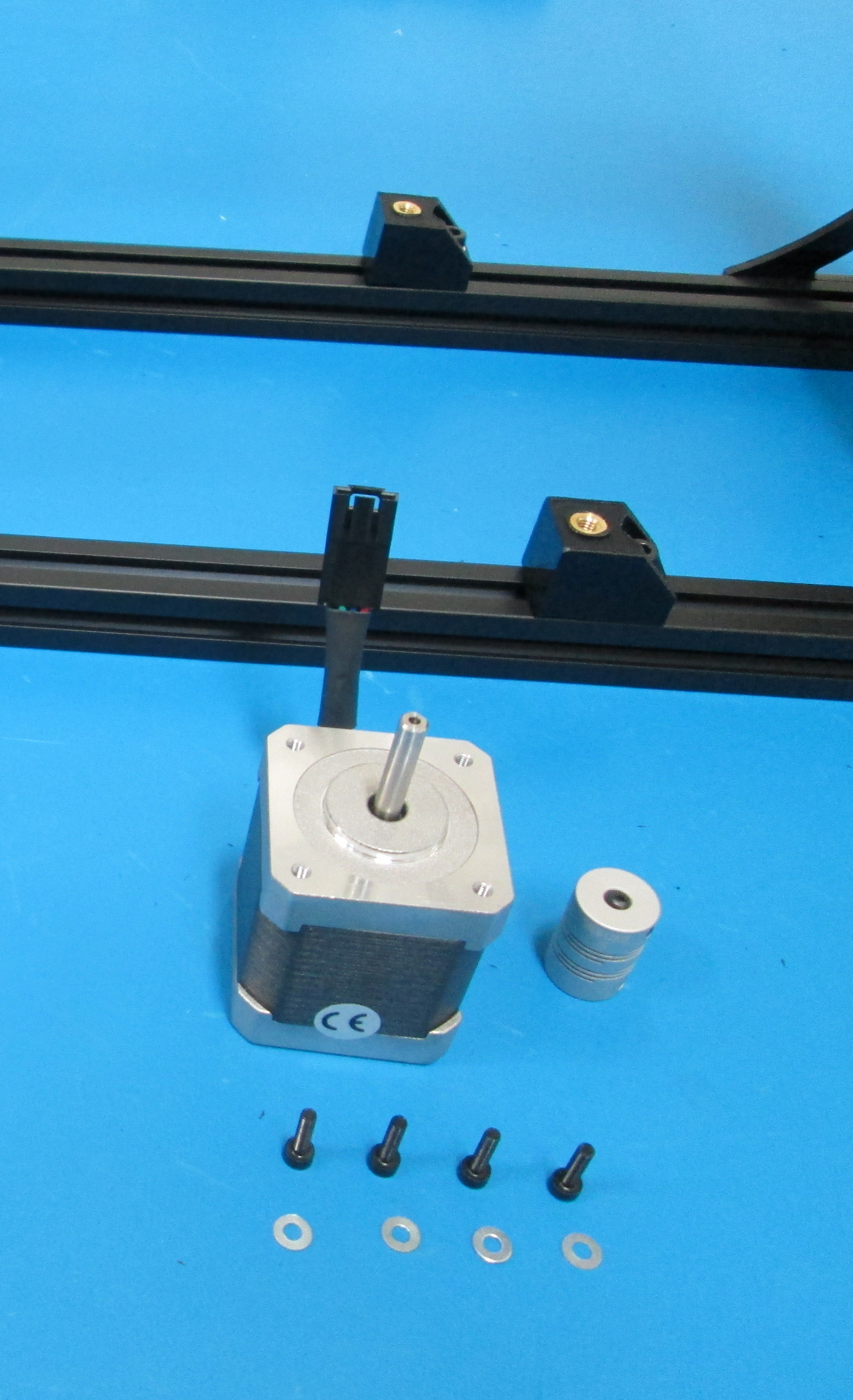
Components
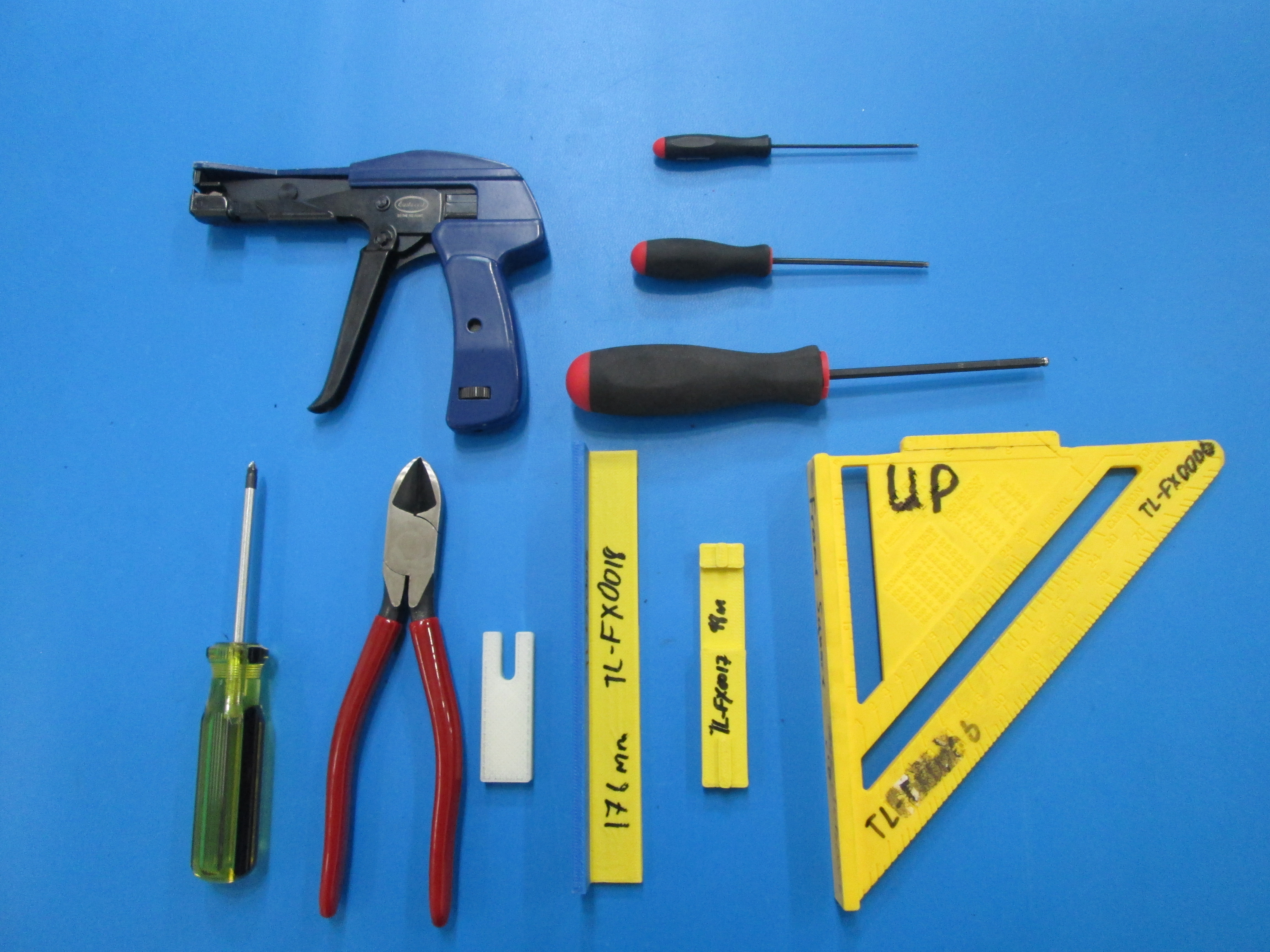
Tools
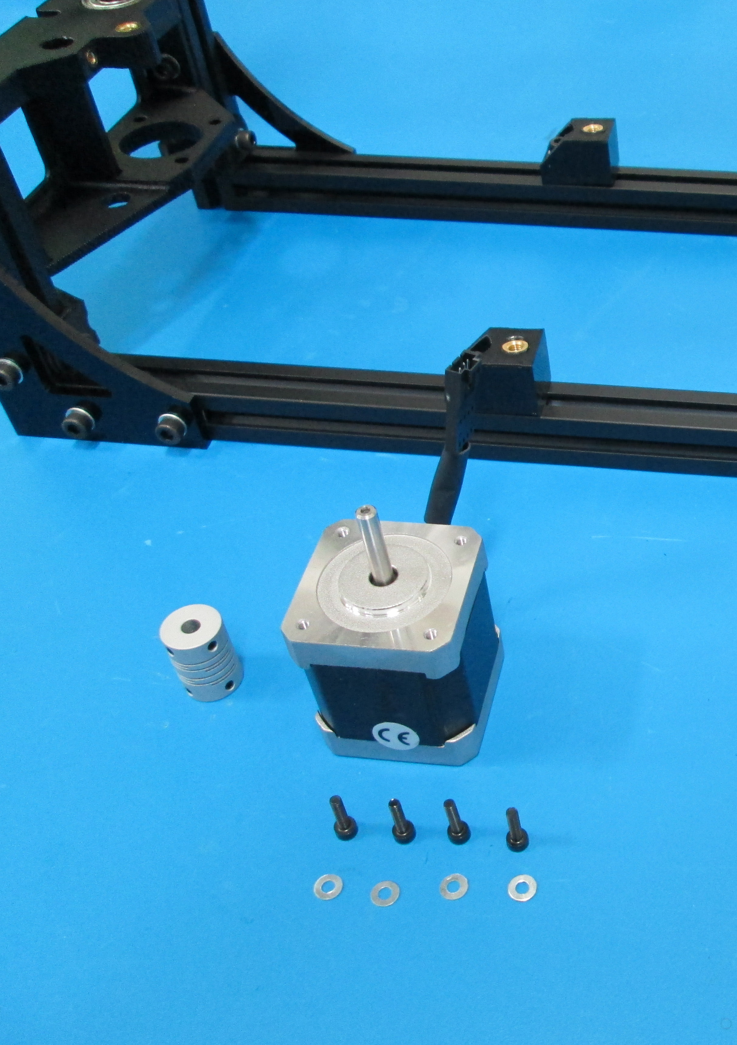
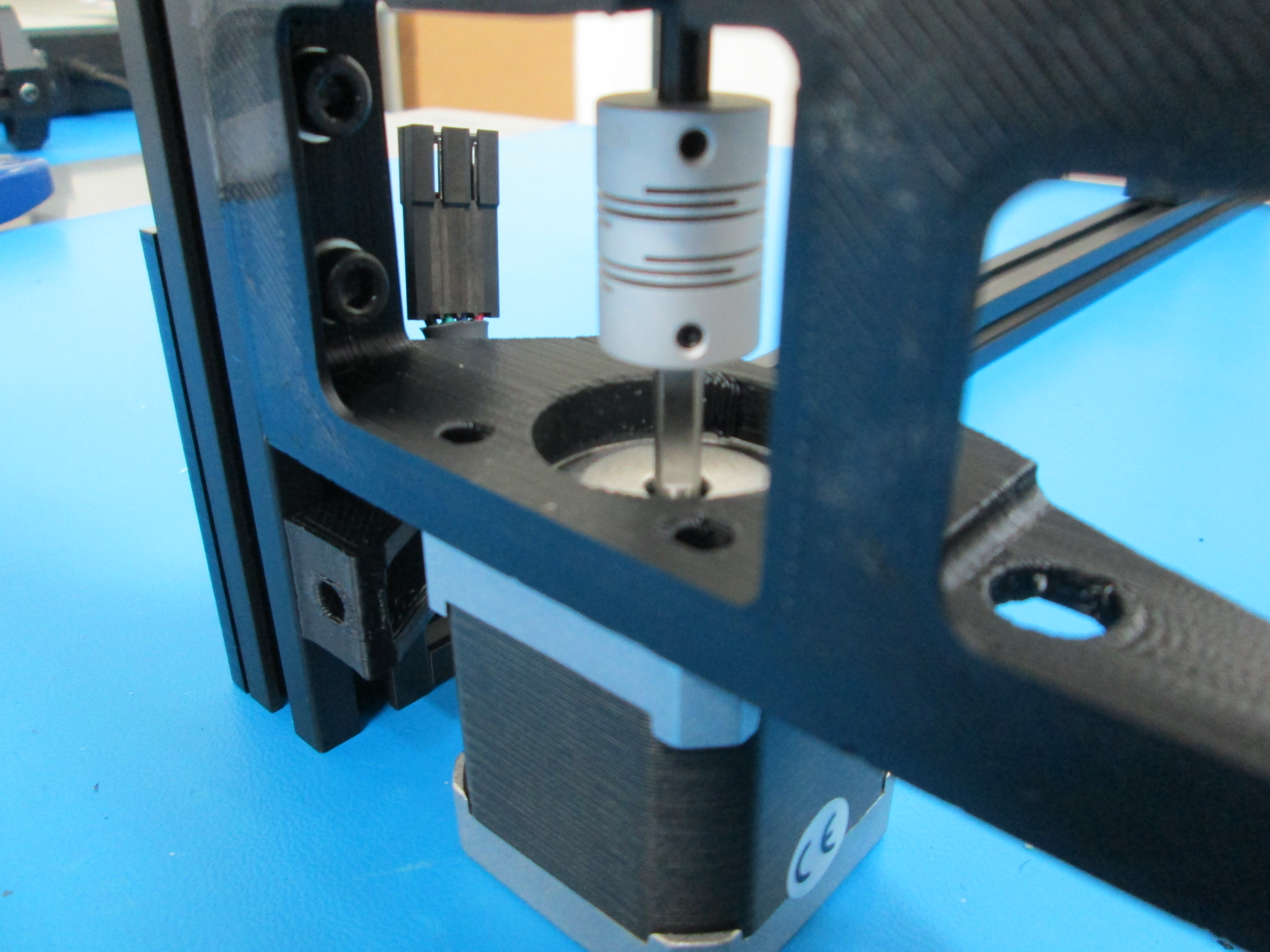
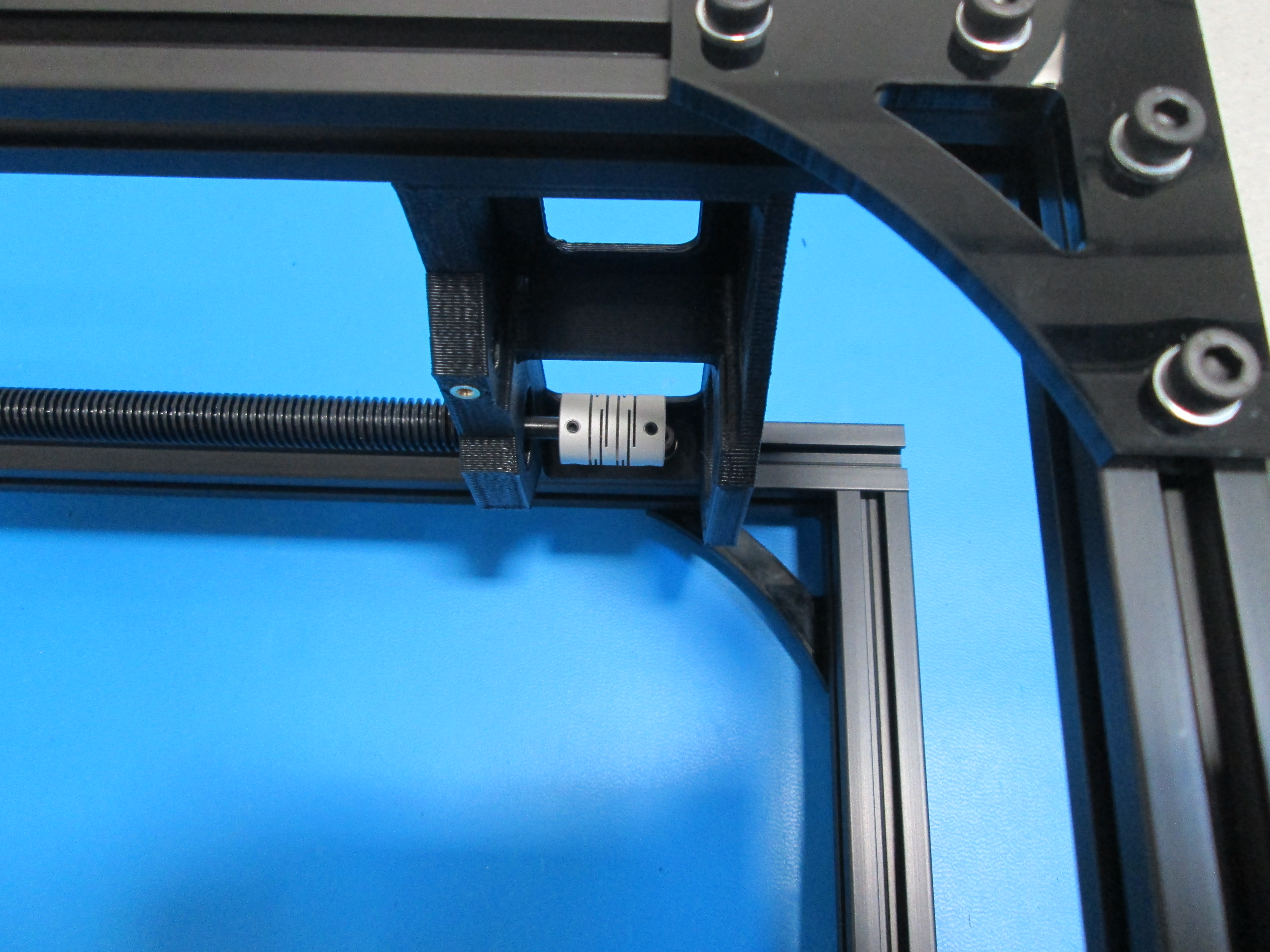
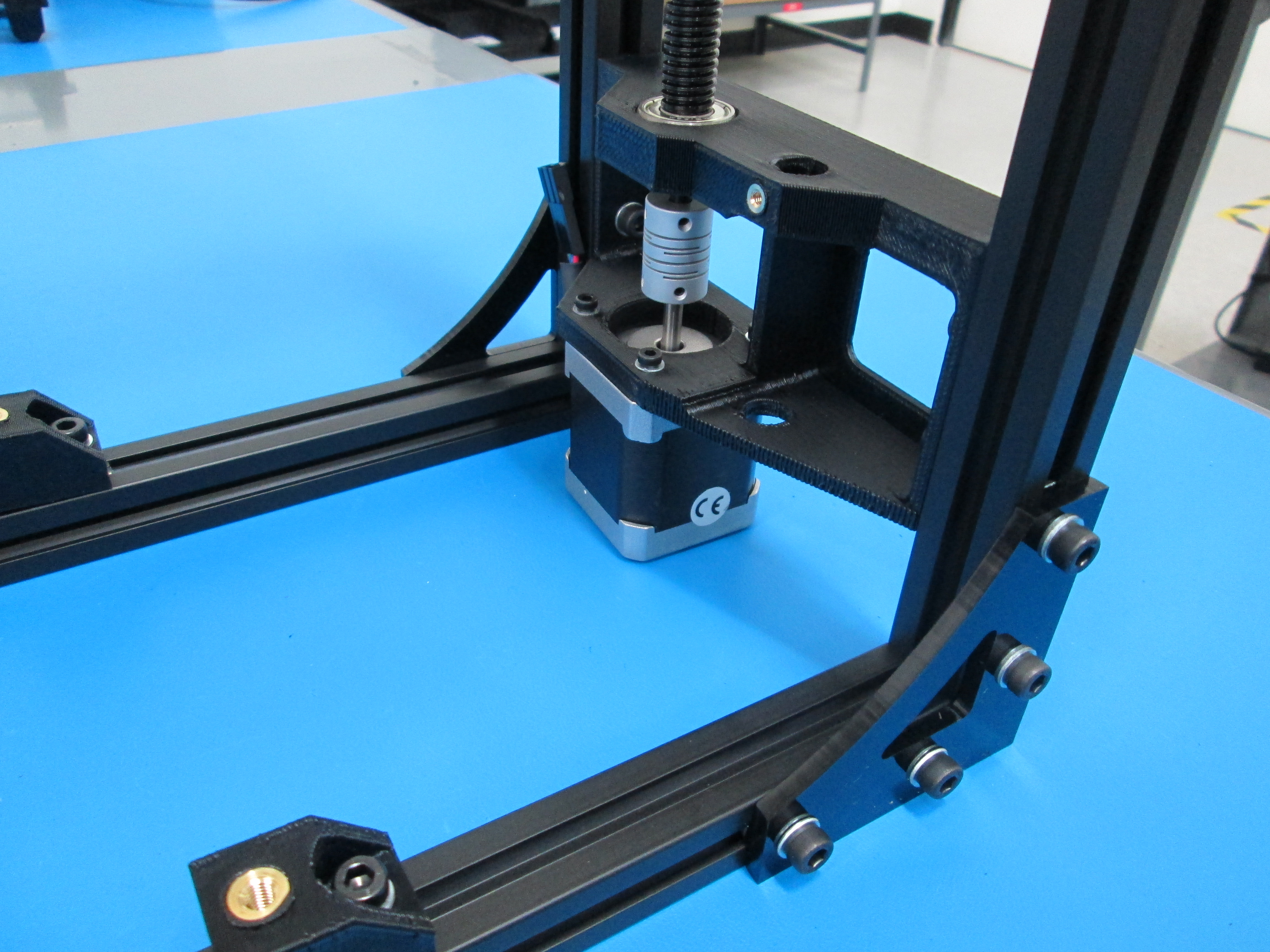
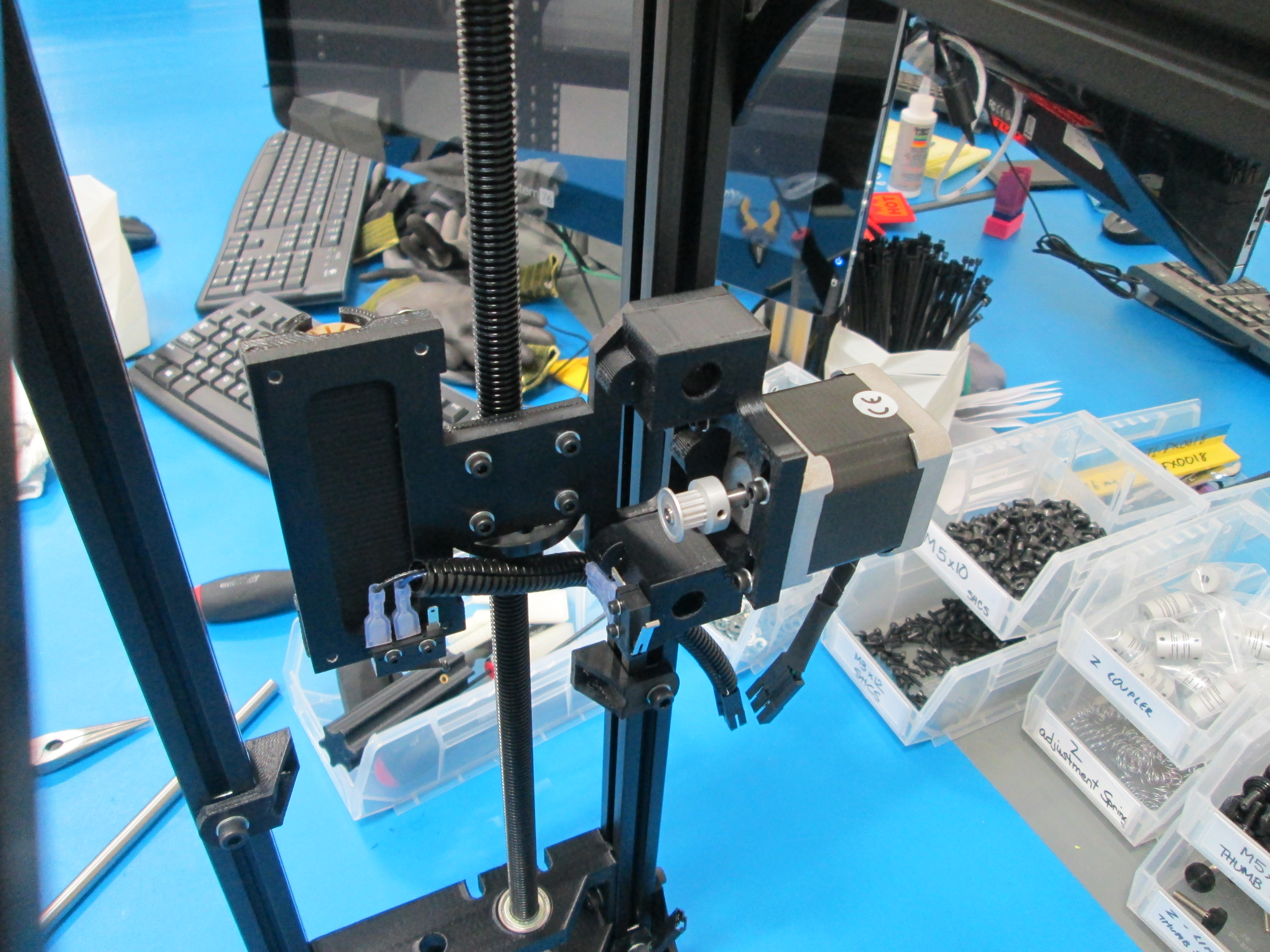
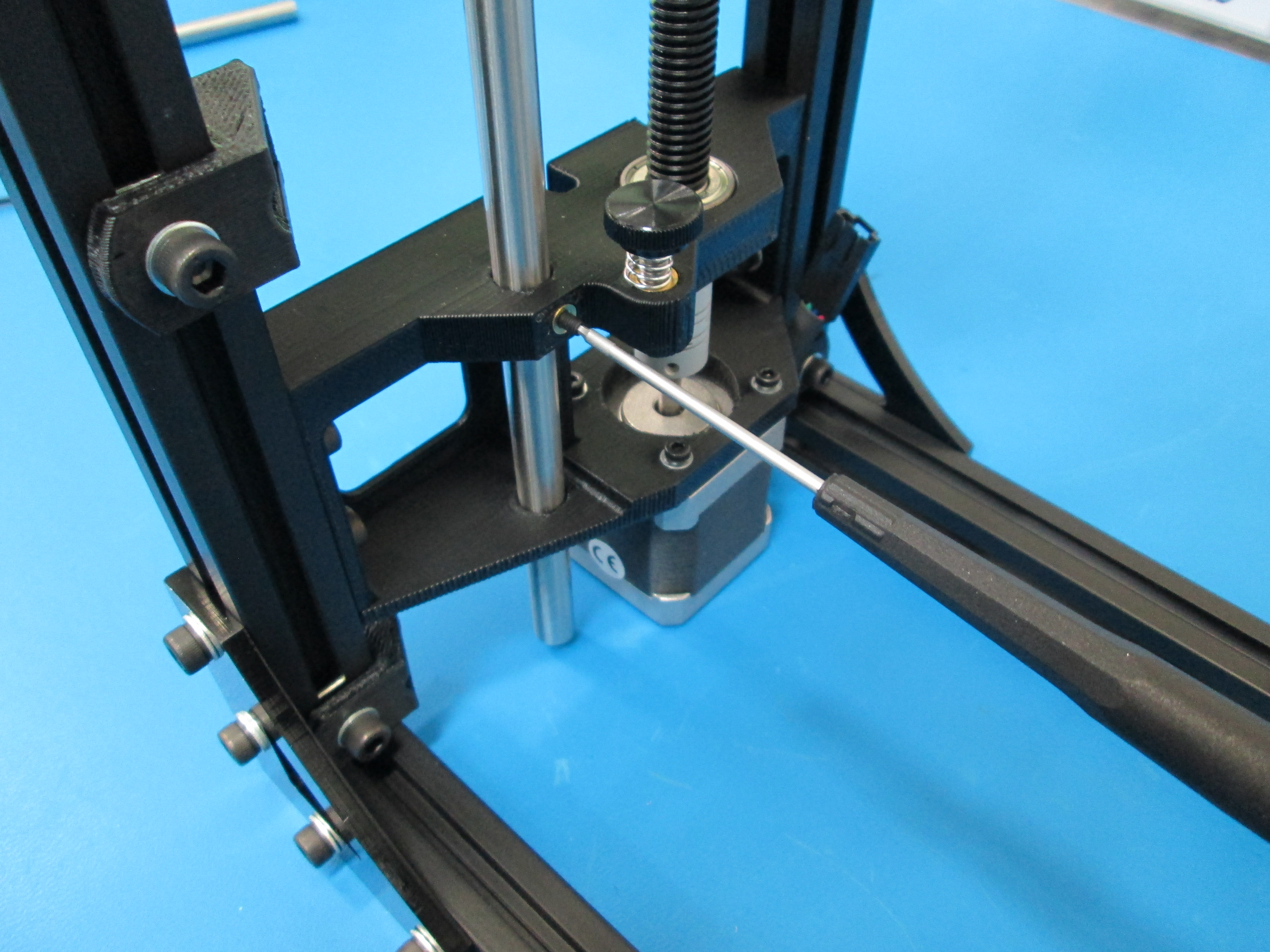
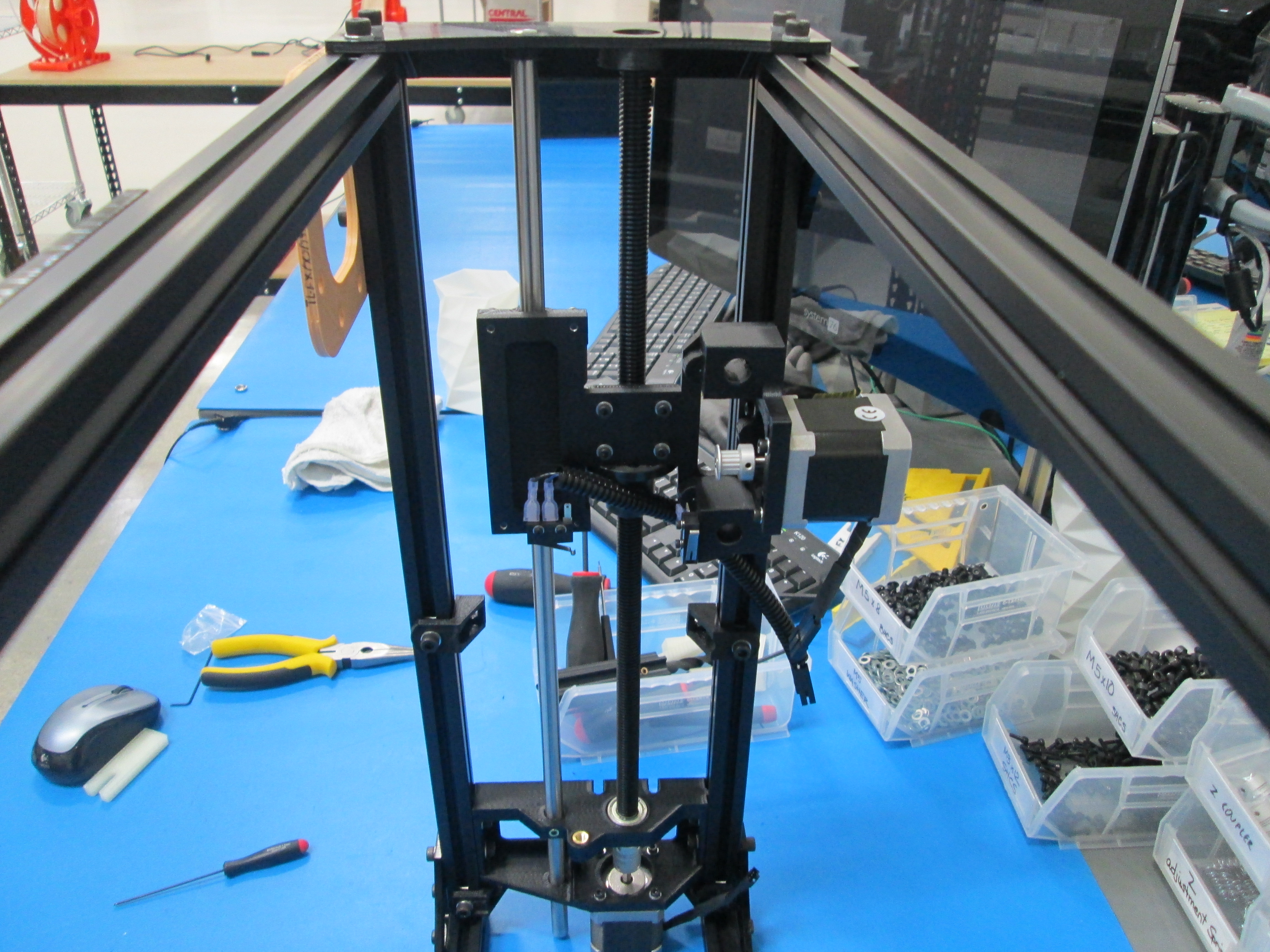
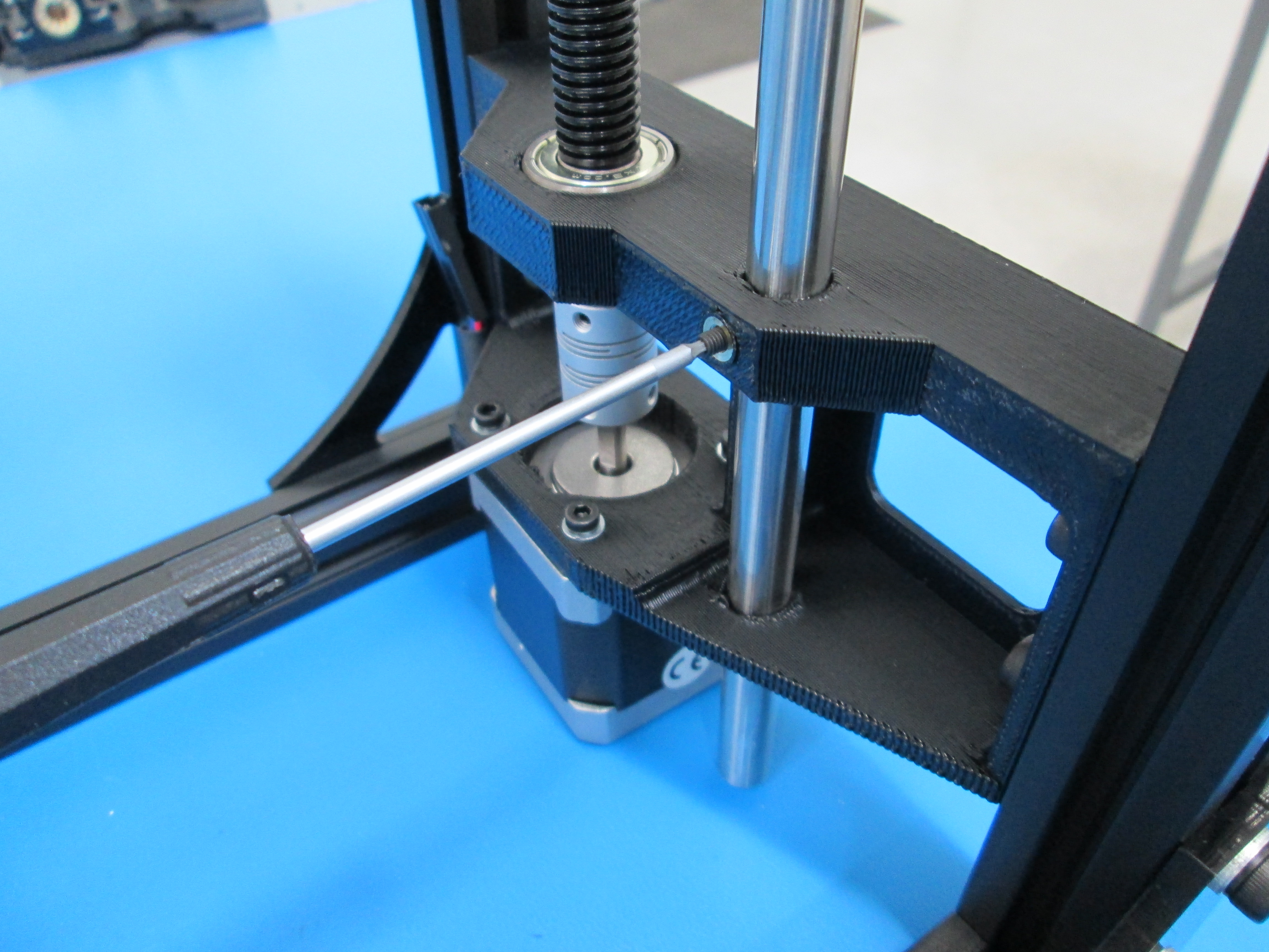
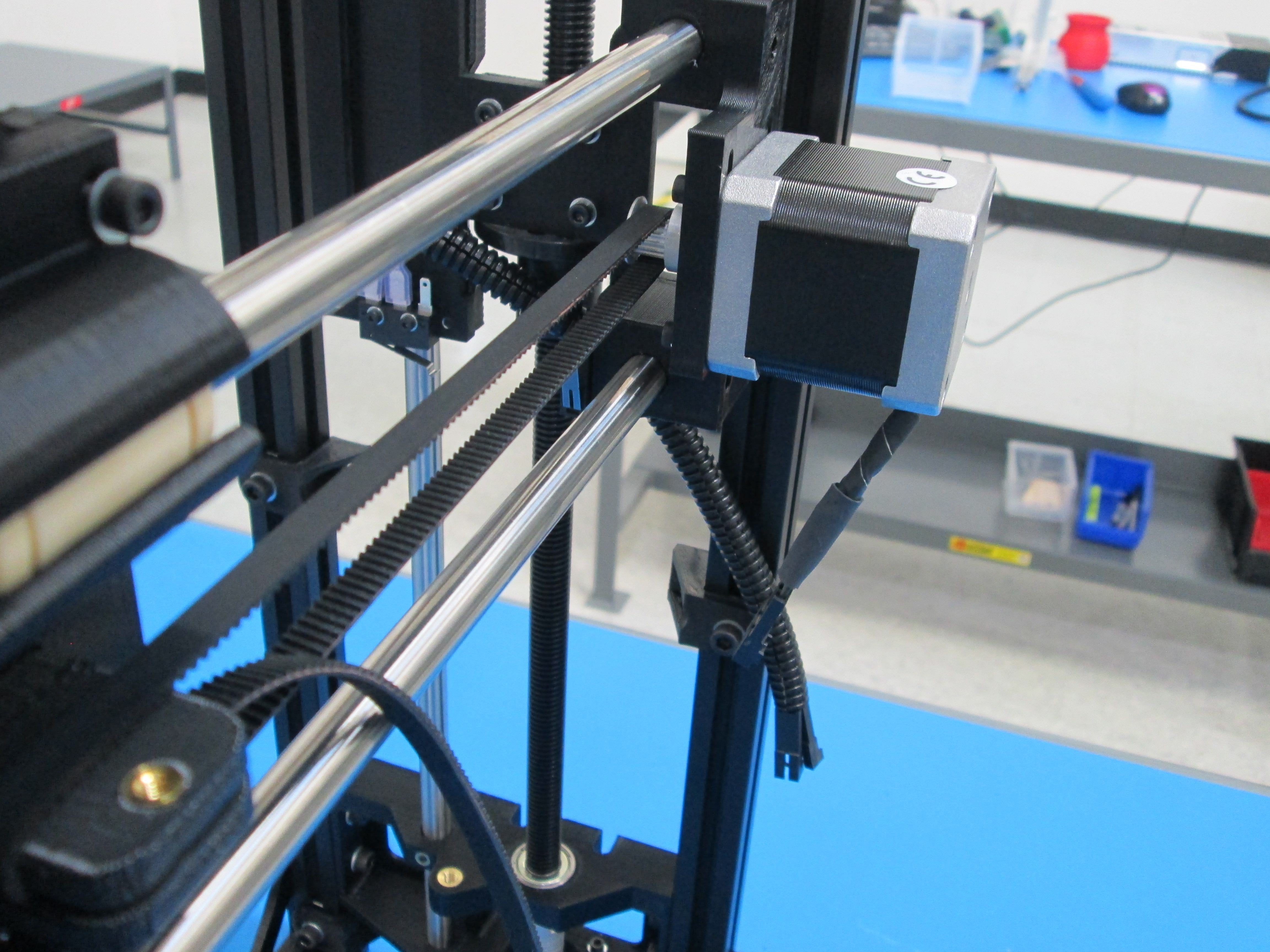
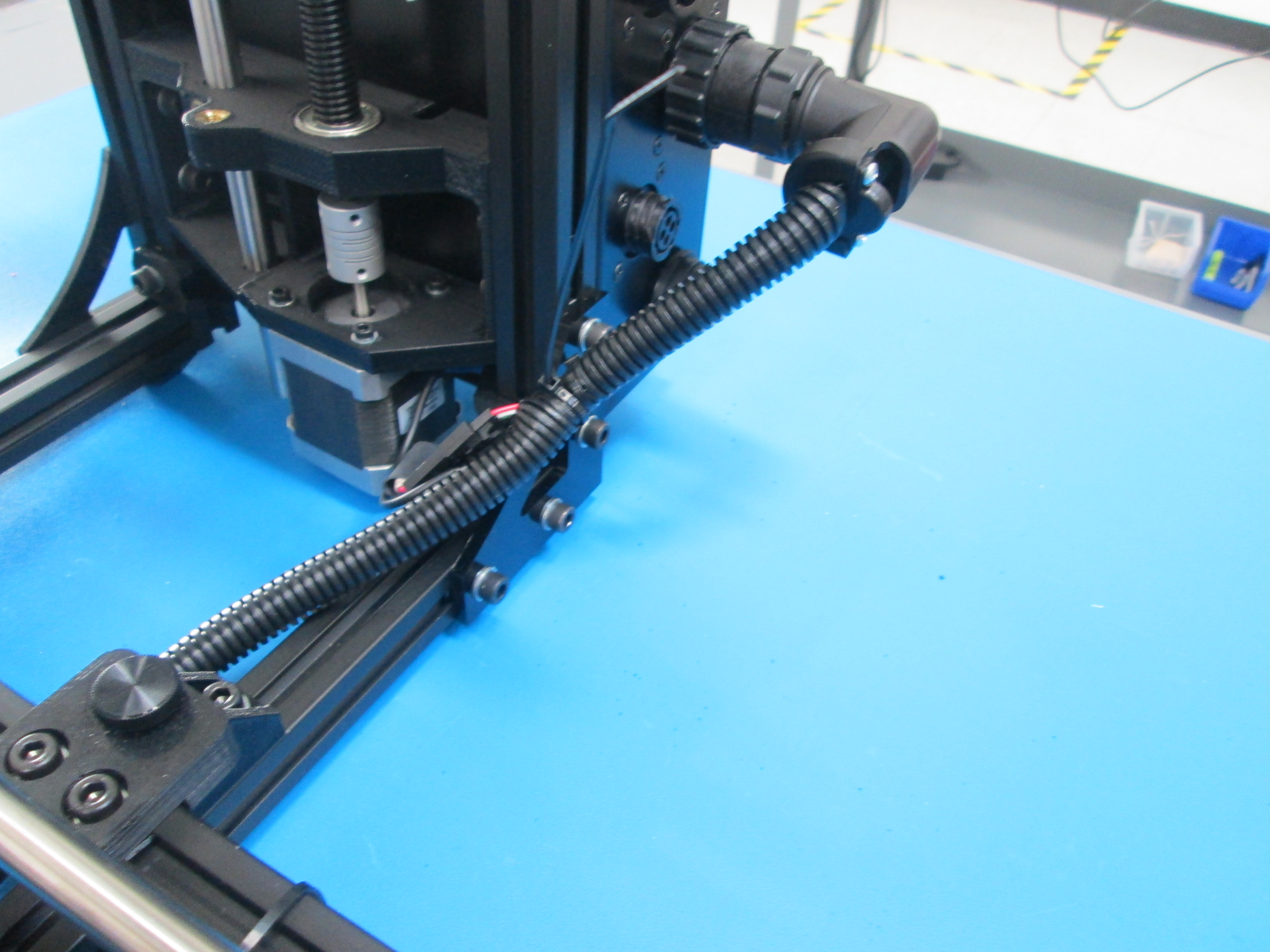
Install drive rod coupler onto drive rod, do not tighten set screws yet.
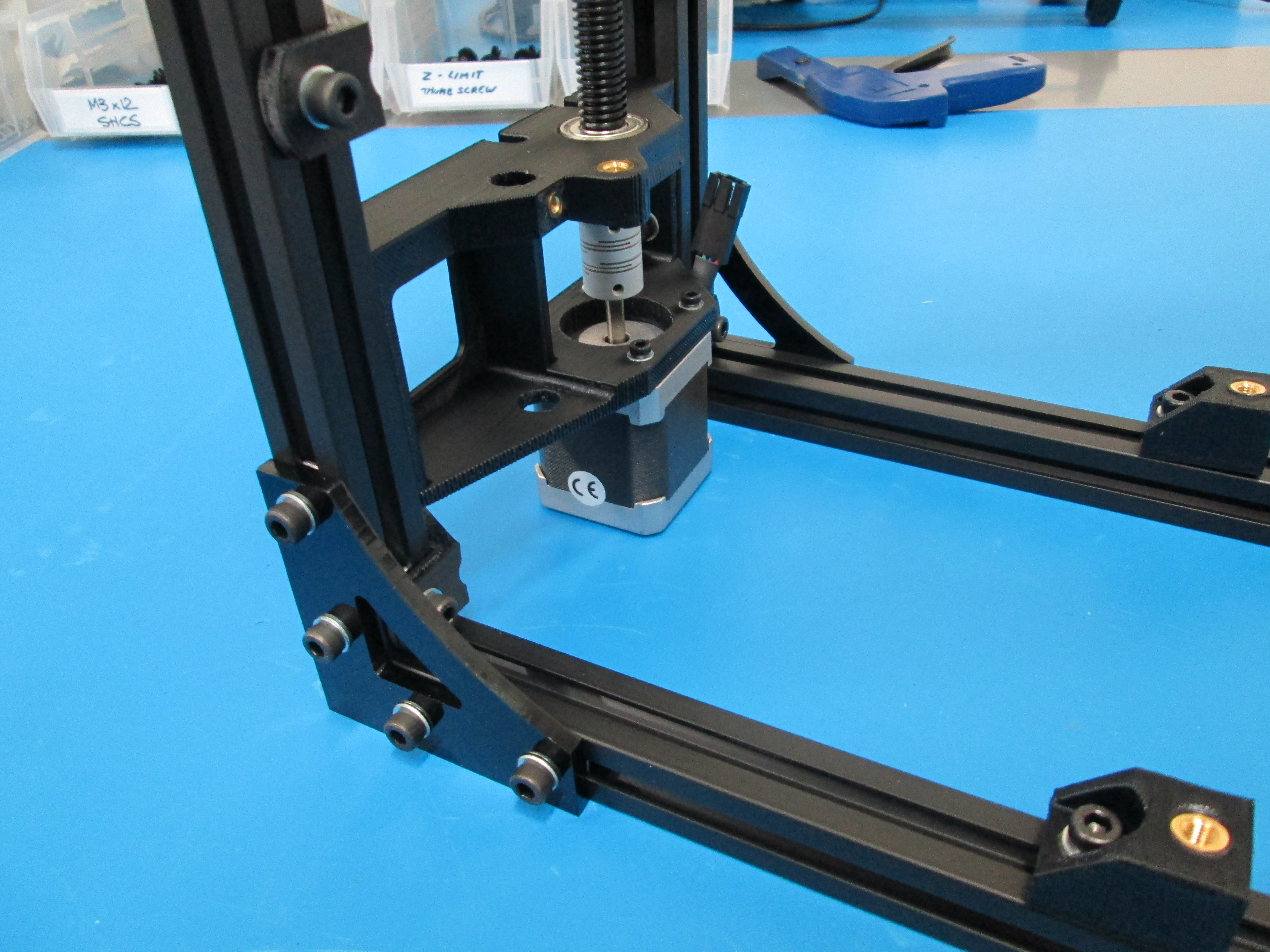
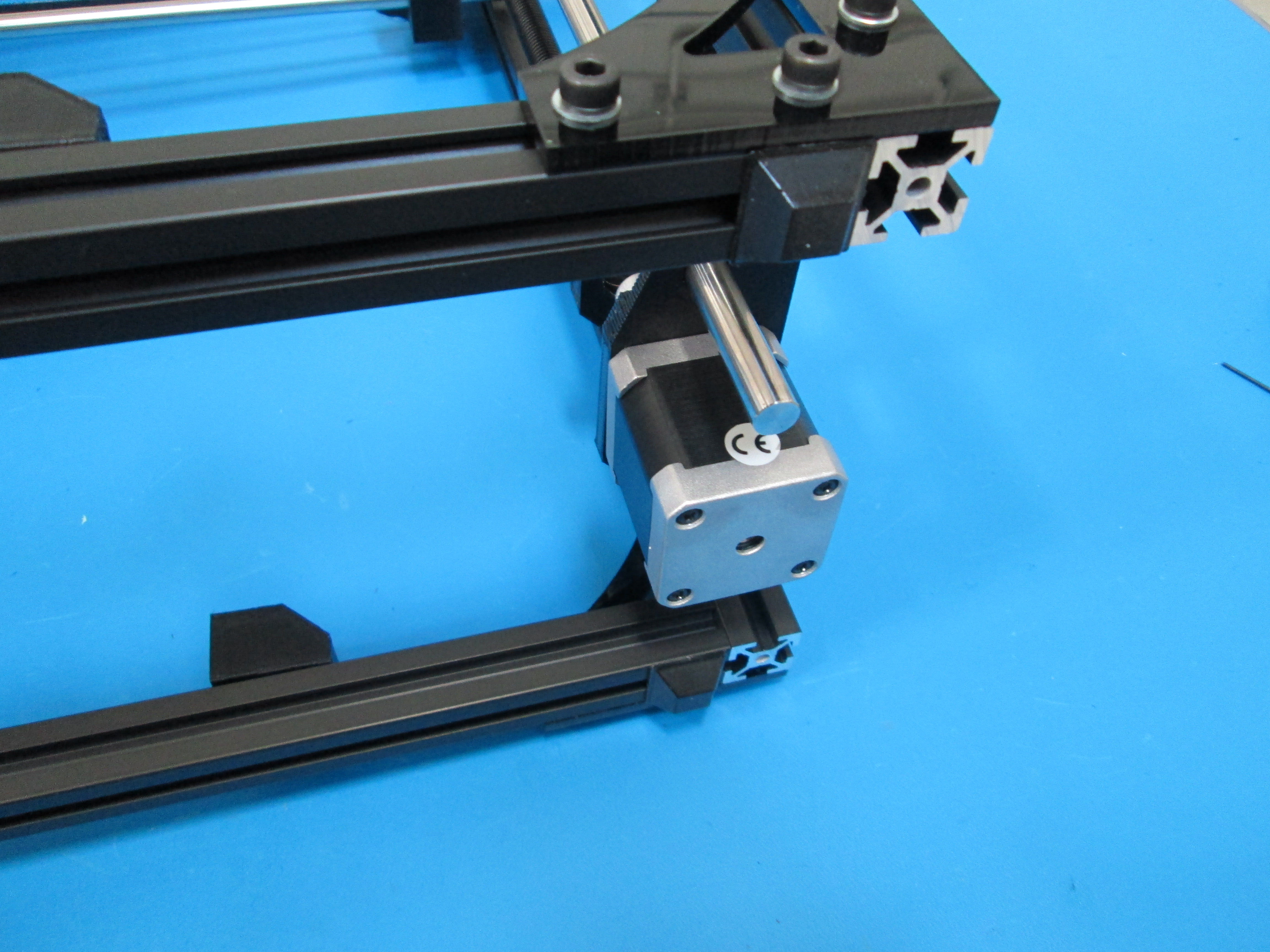
Next, install Z motor, orient wires to the back. Use 4x M3x12 SHCS and M3 washers to secure motor.
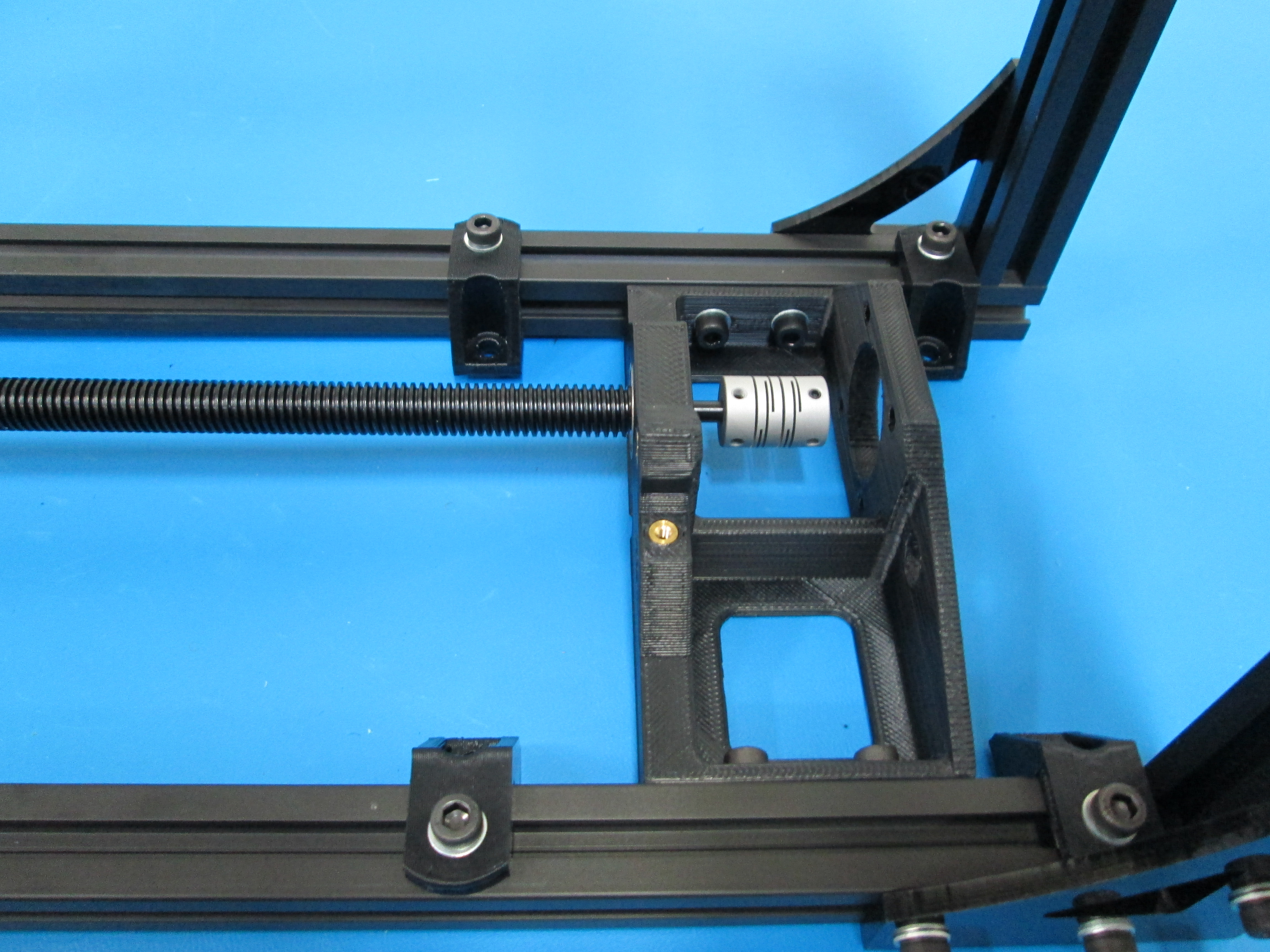
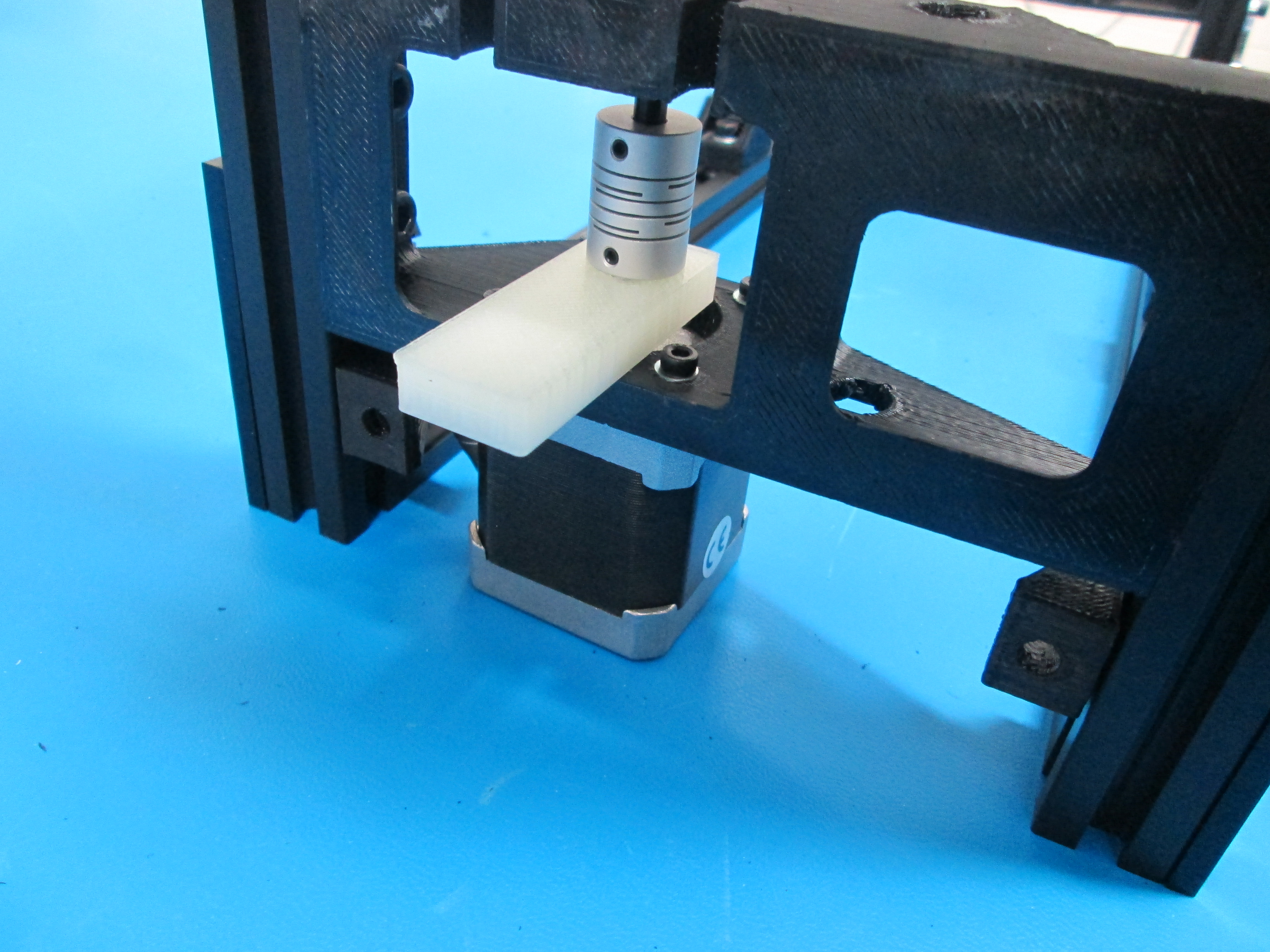
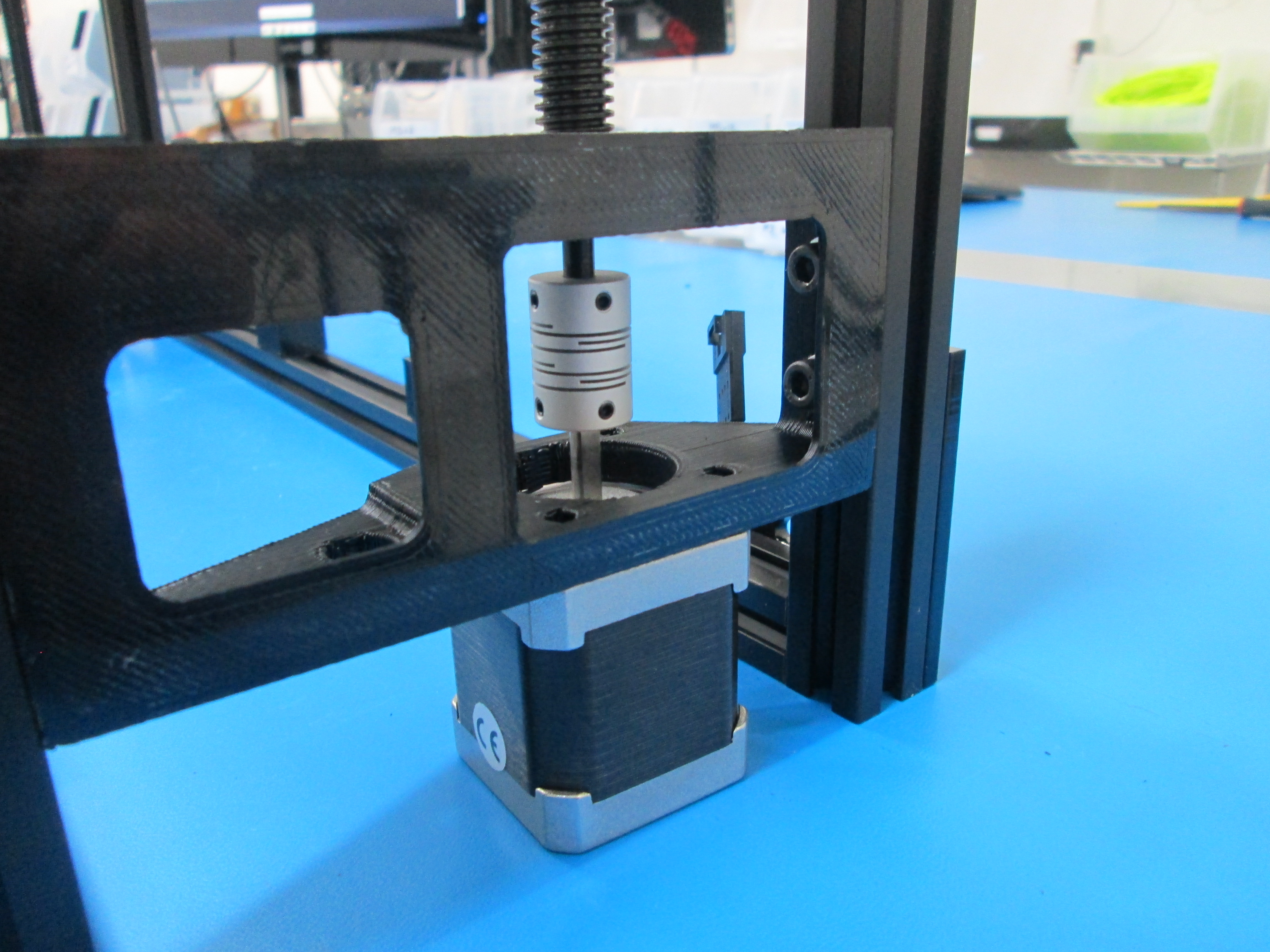
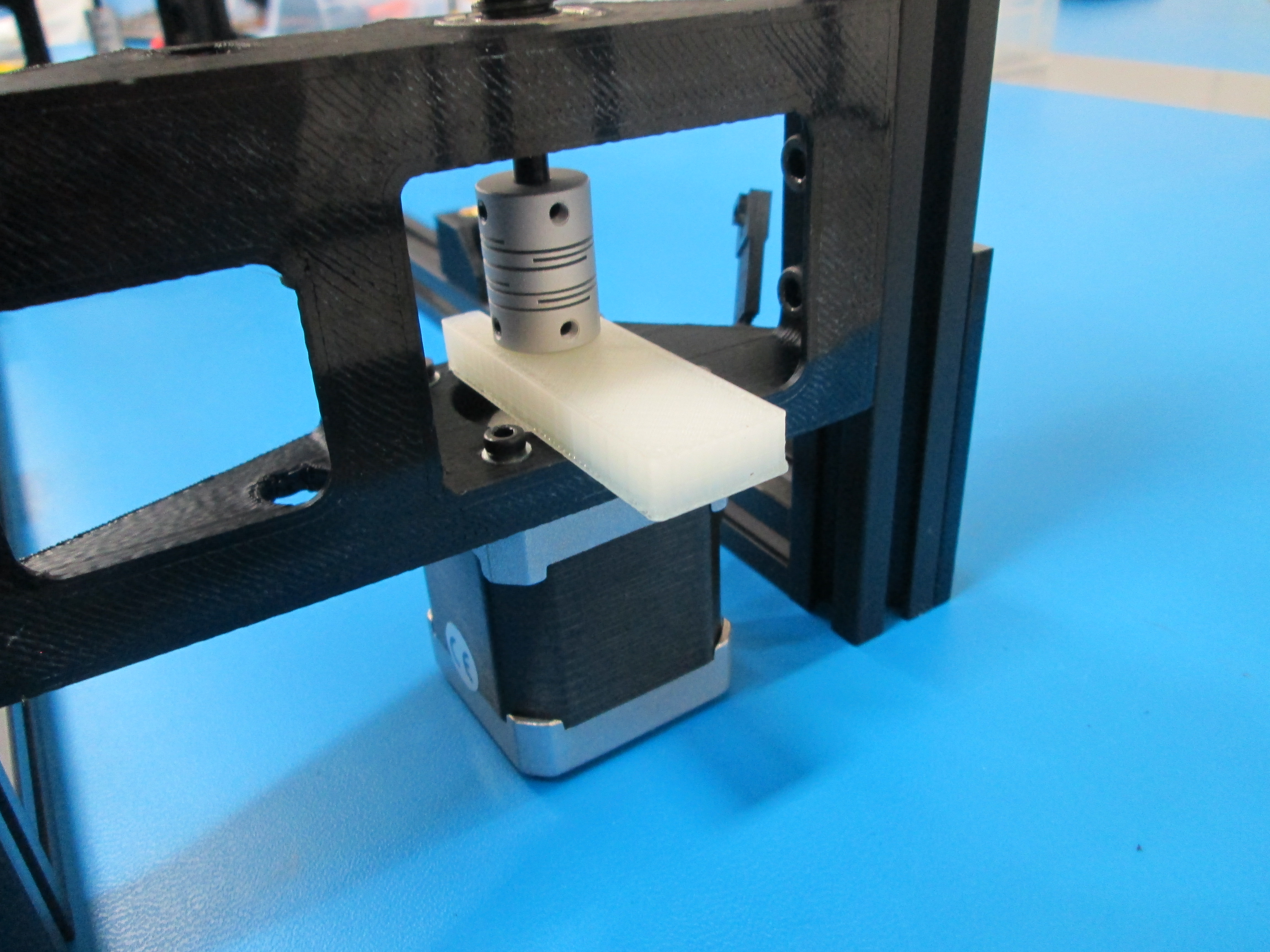
Use 8 mm spacer to set the height of the drive rod coupler. Or measure 8 mm from Z motor mount to bottom of coupler.
Make sure that one set of the coupler set screws lines up with the flat of the drive rod and flat of the motor shaft, then tighten set screws.
Tip: You may need to loosen the bolts that hold the motor to help align the coupler.
Install drive rod coupler onto drive rod, do not tighten set screws yet.
Next, install Z motor, orient wires to the back. Use 4x M3x12 SHCS and M3 washers to secure motor.
Use 8 mm spacer to set the height of the drive rod coupler. Or measure 8 mm from Z motor mount to bottom of coupler.
Make sure that one set of the coupler set screws lines up with the flat of the drive rod and flat of the motor shaft, then tighten set screws.
Tip: You may need to loosen the bolts that hold the motor to help align the coupler.
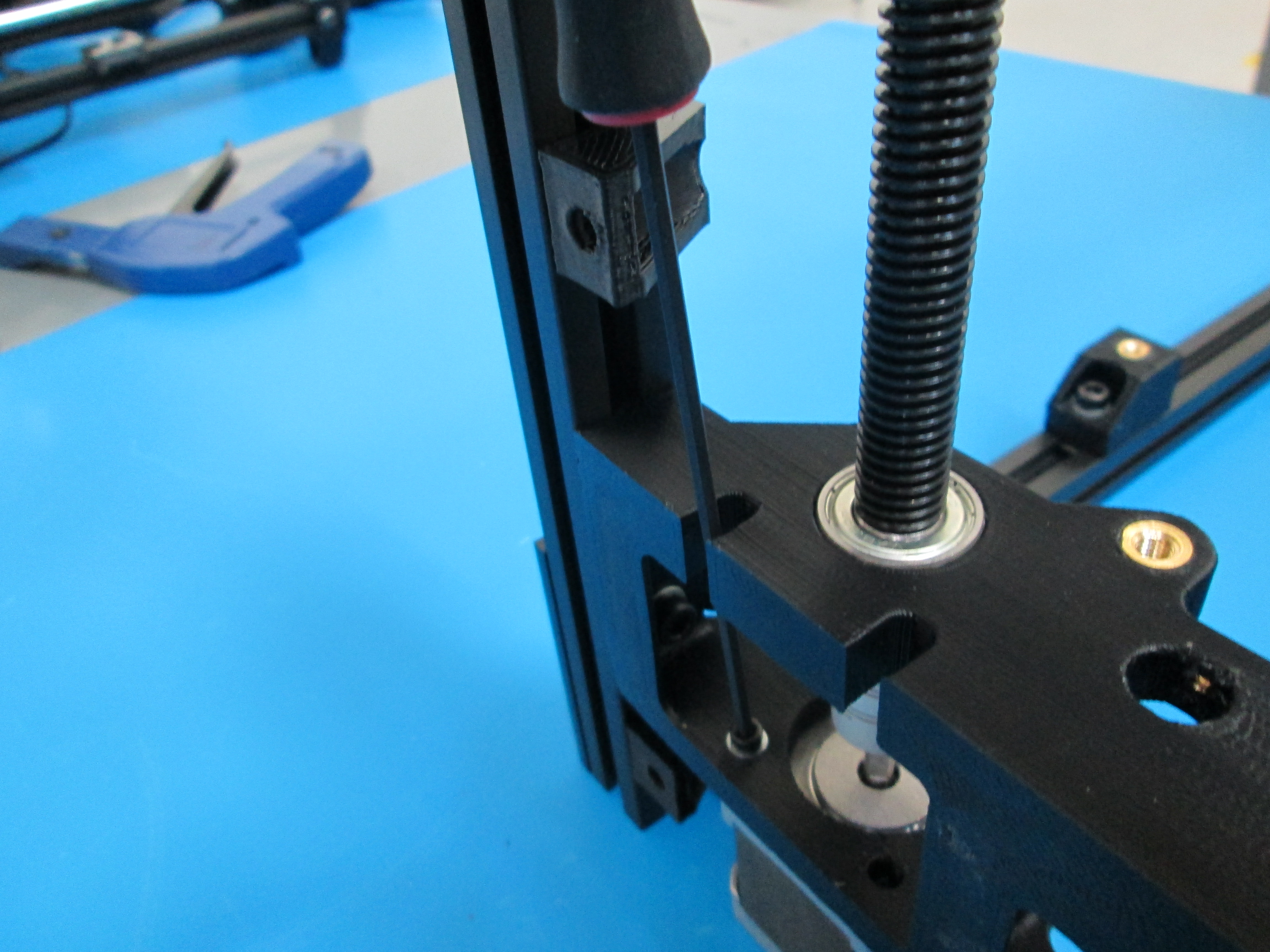
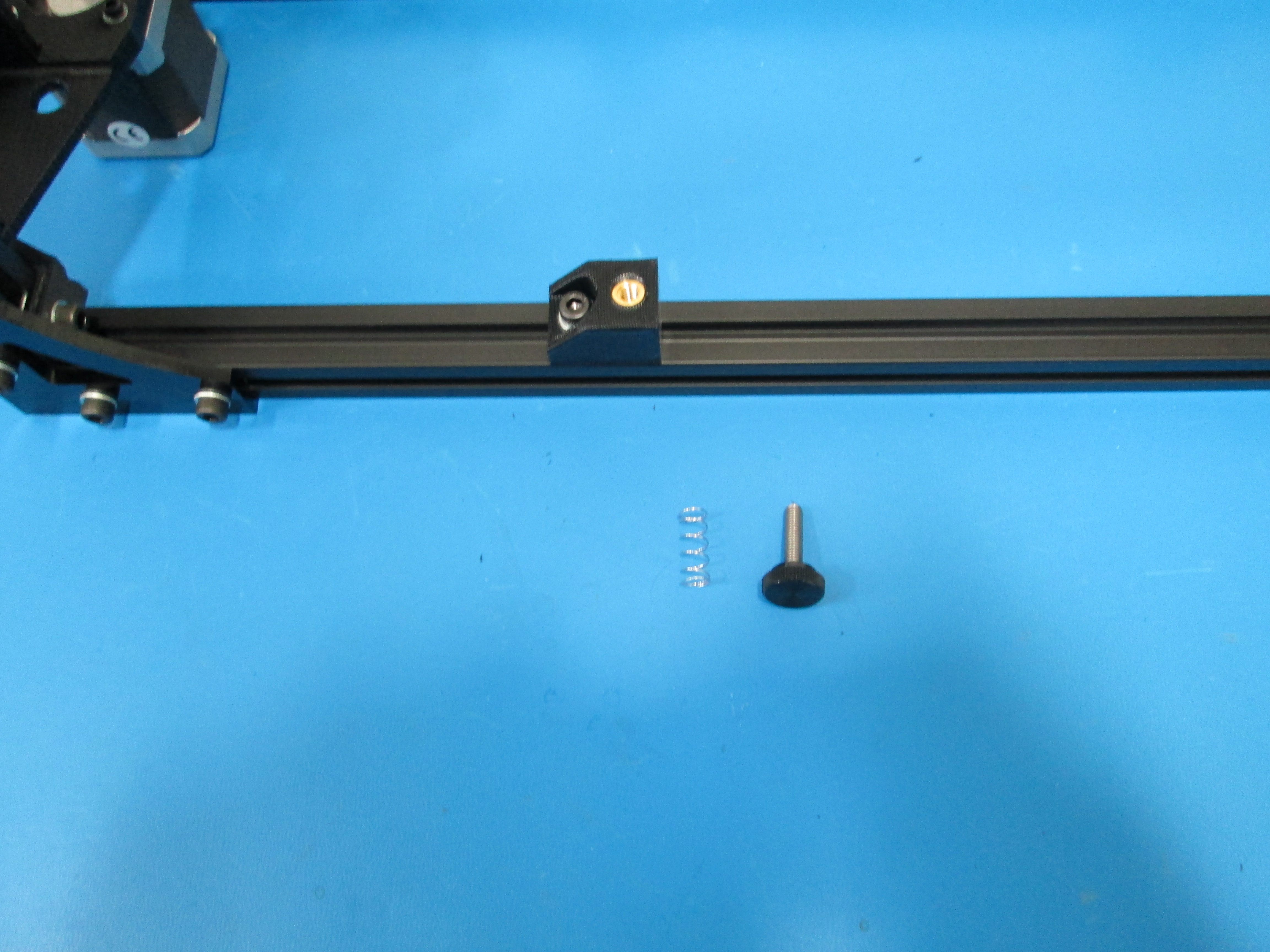
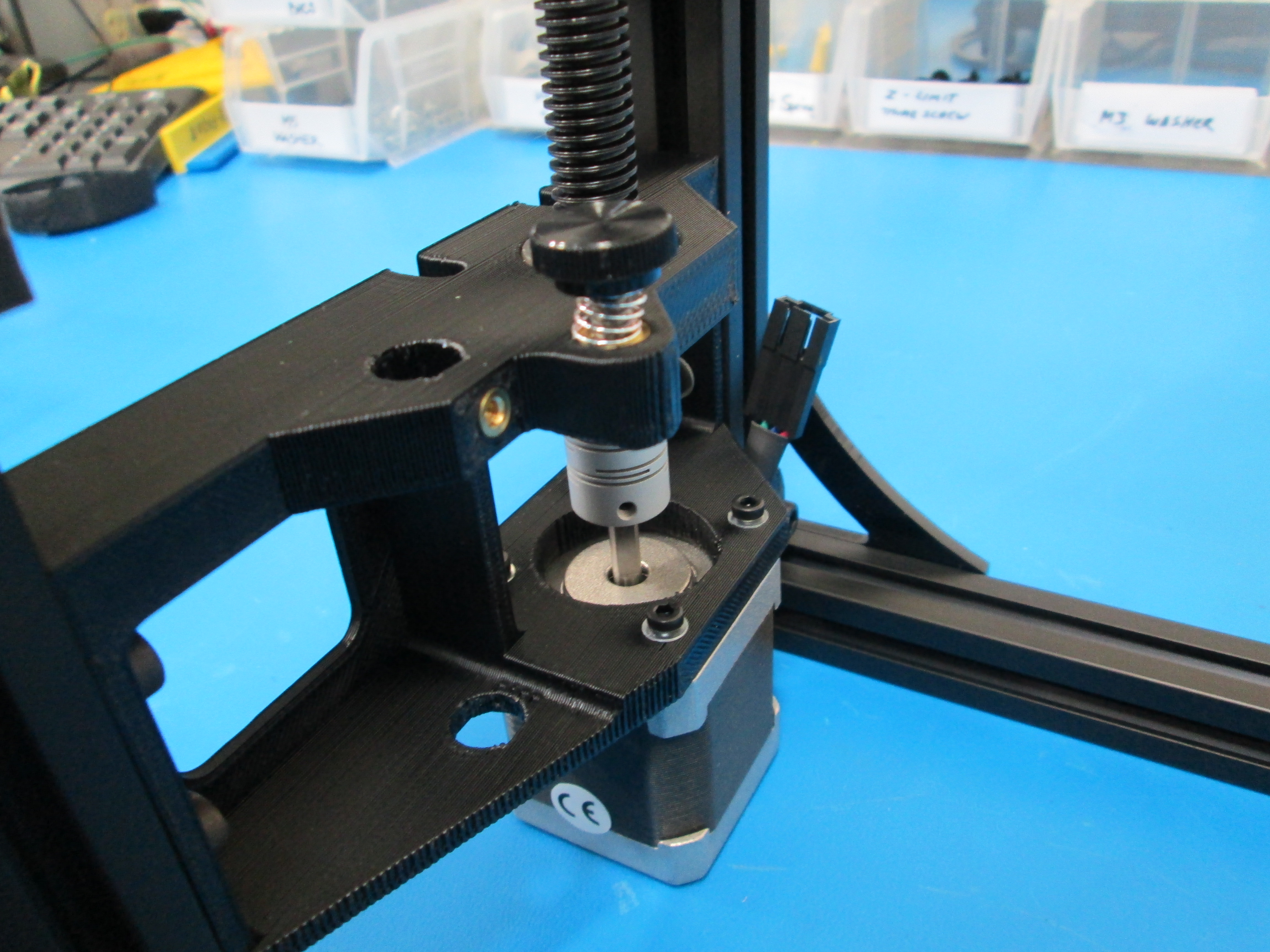
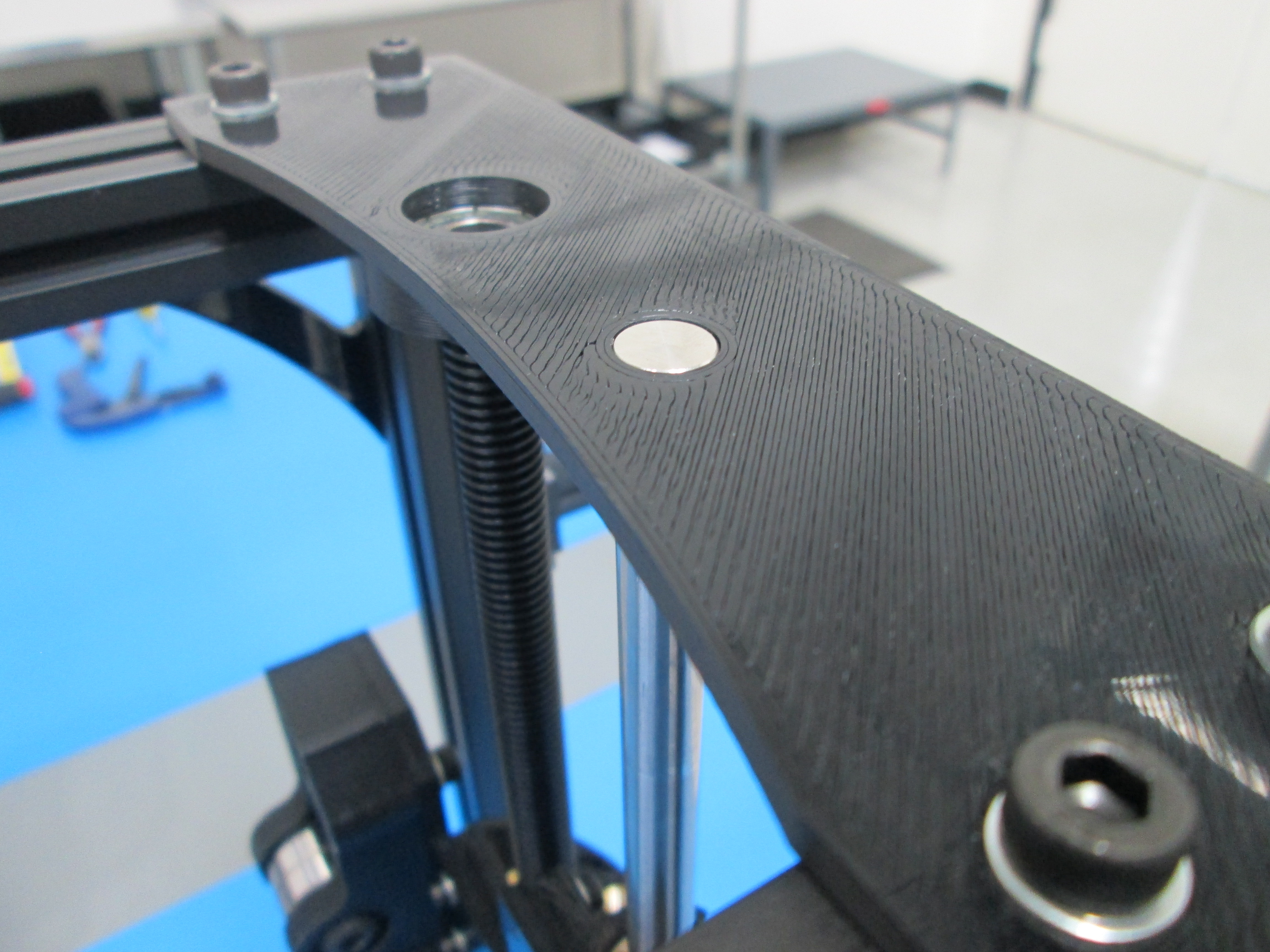
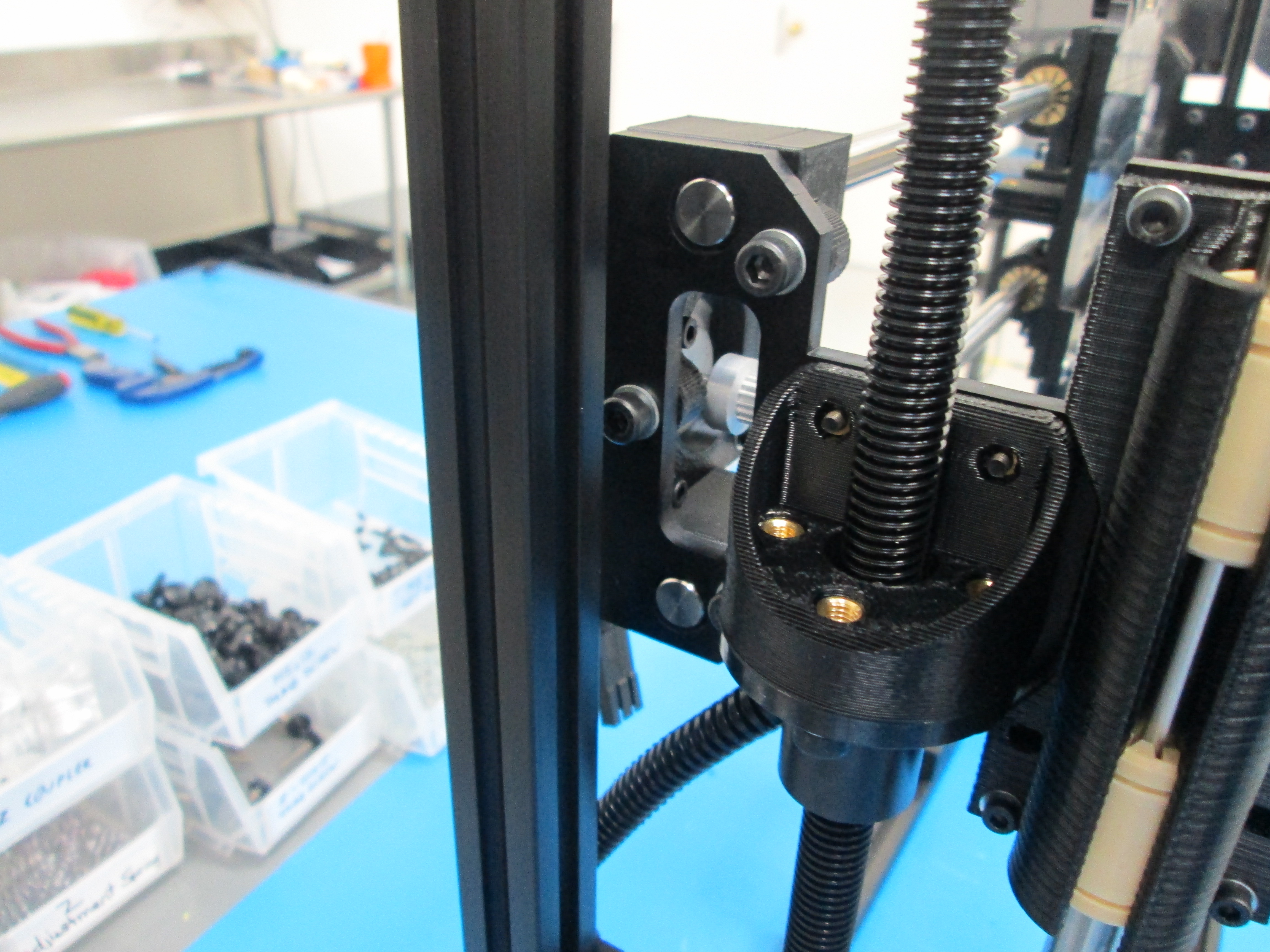
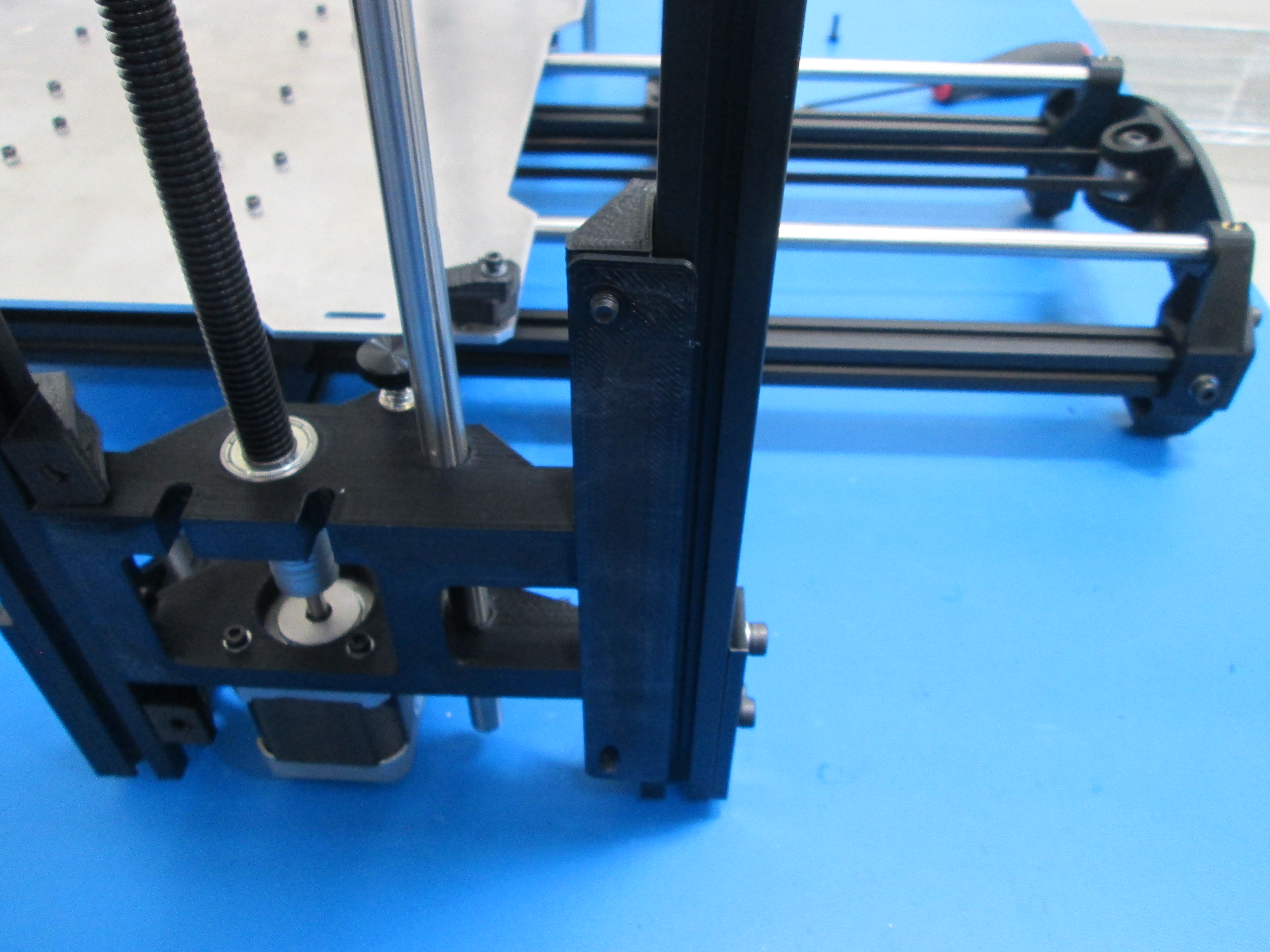
Place Z adjustment spring on M5x20 thumb screw. Then thread thumb screw into the threaded insert on the left Z motor mount.
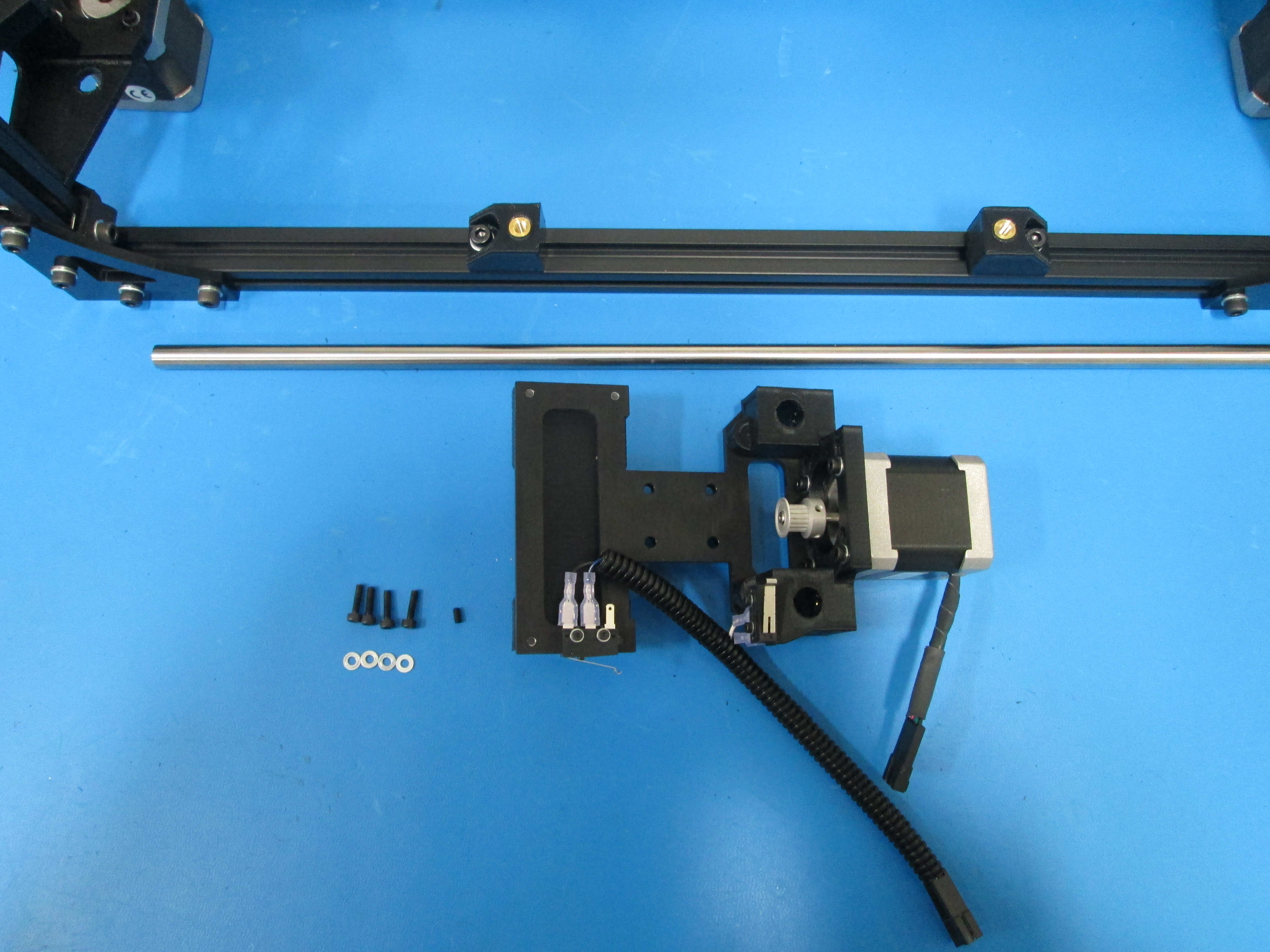
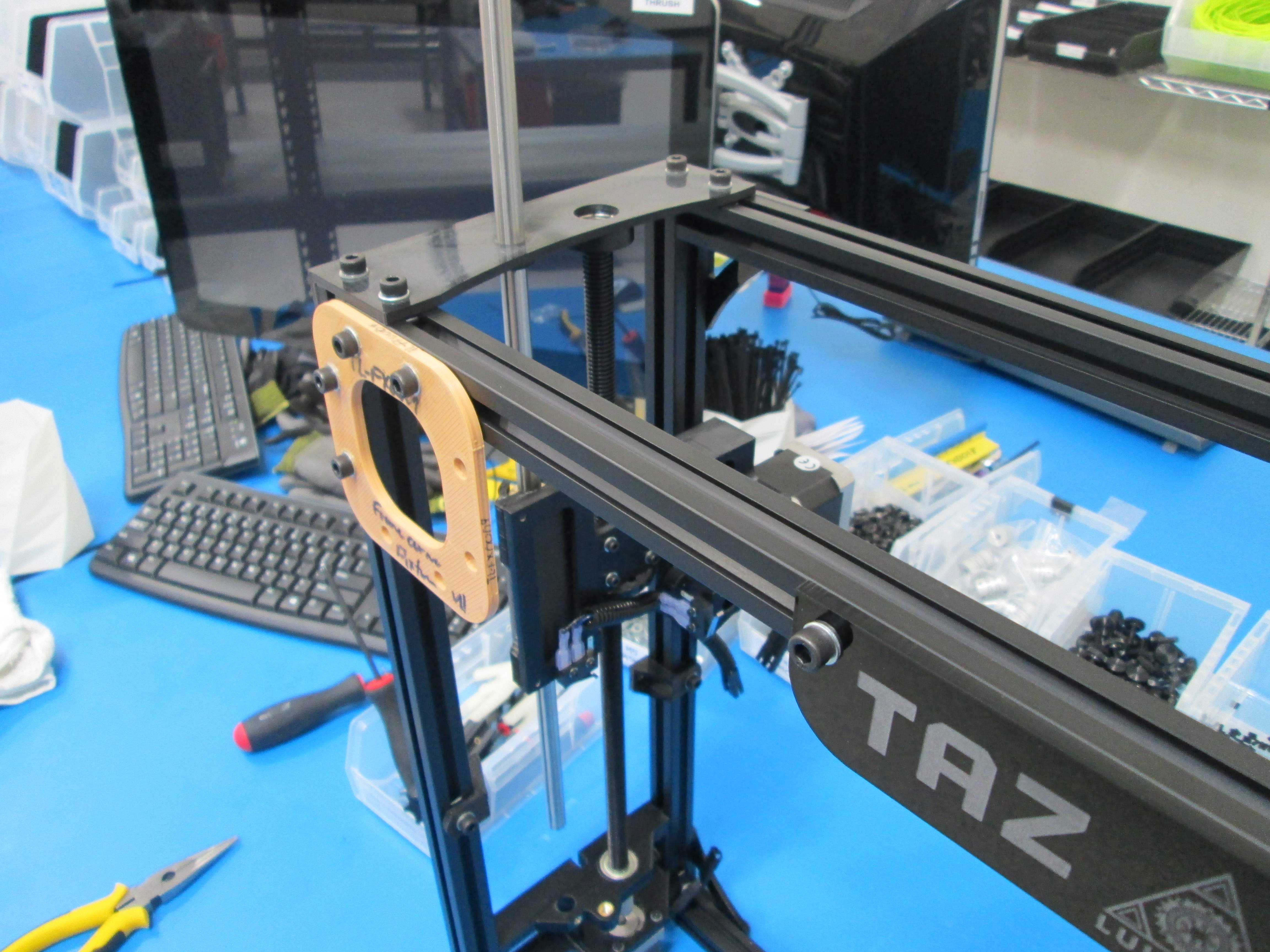
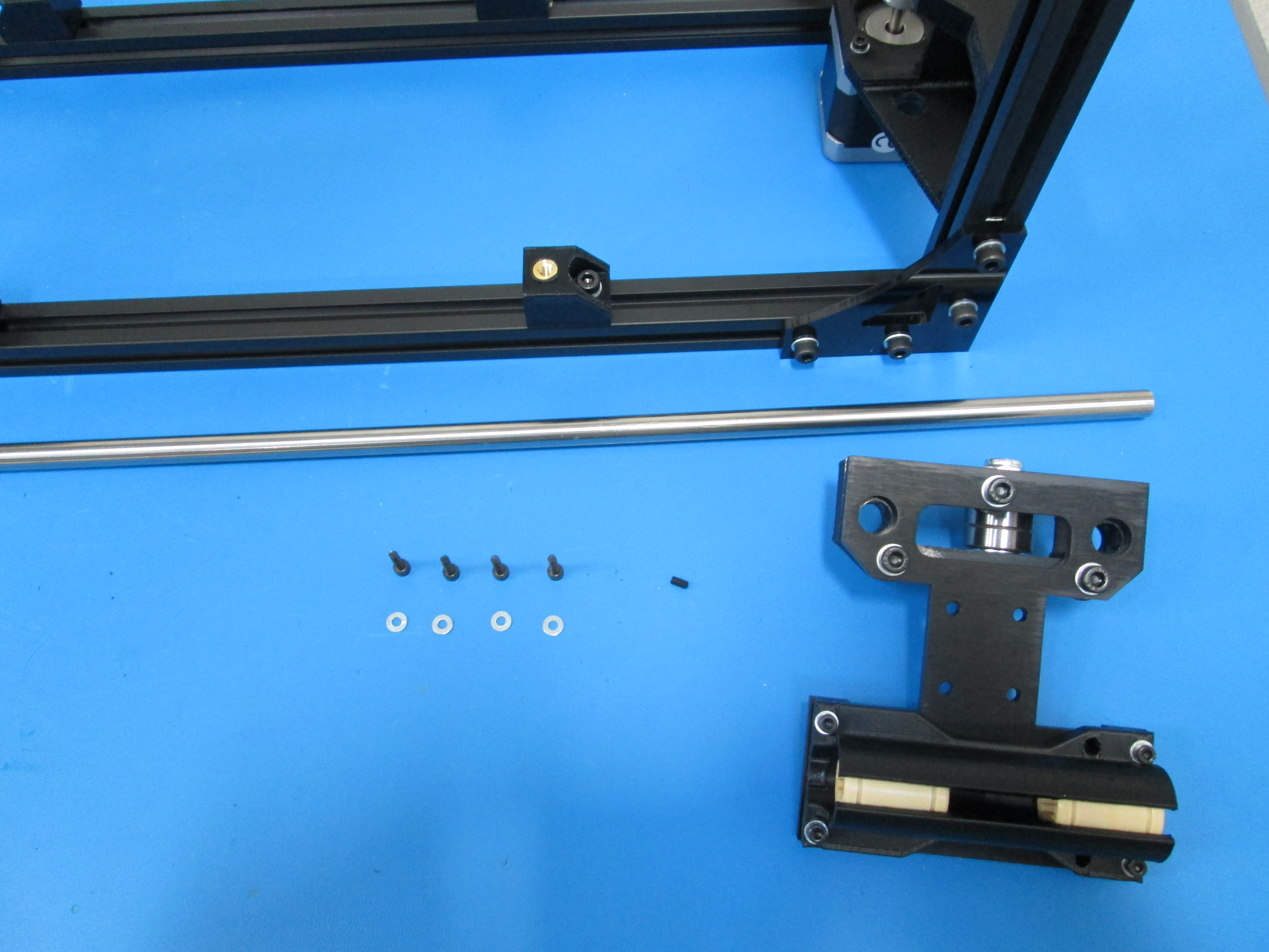
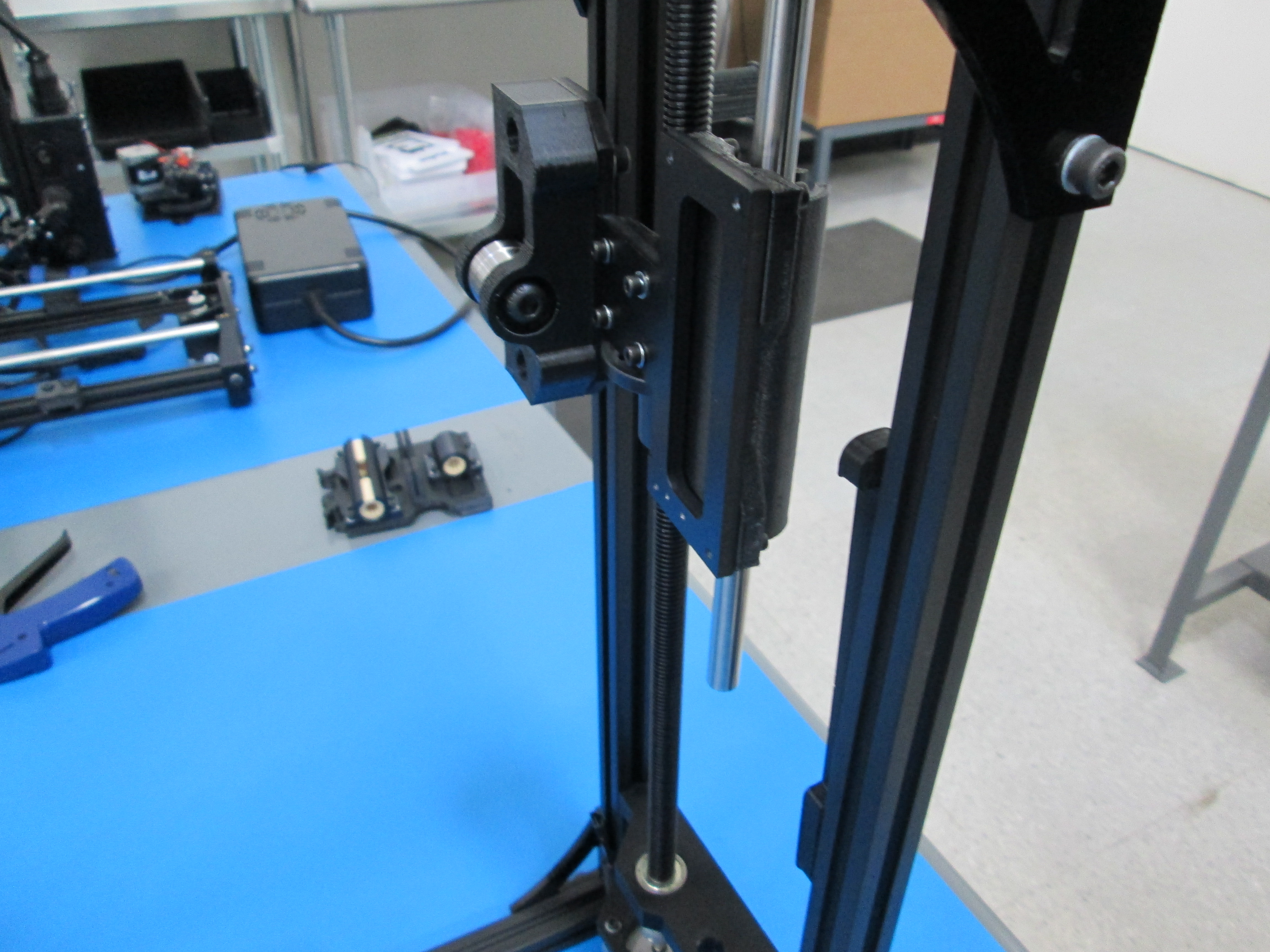
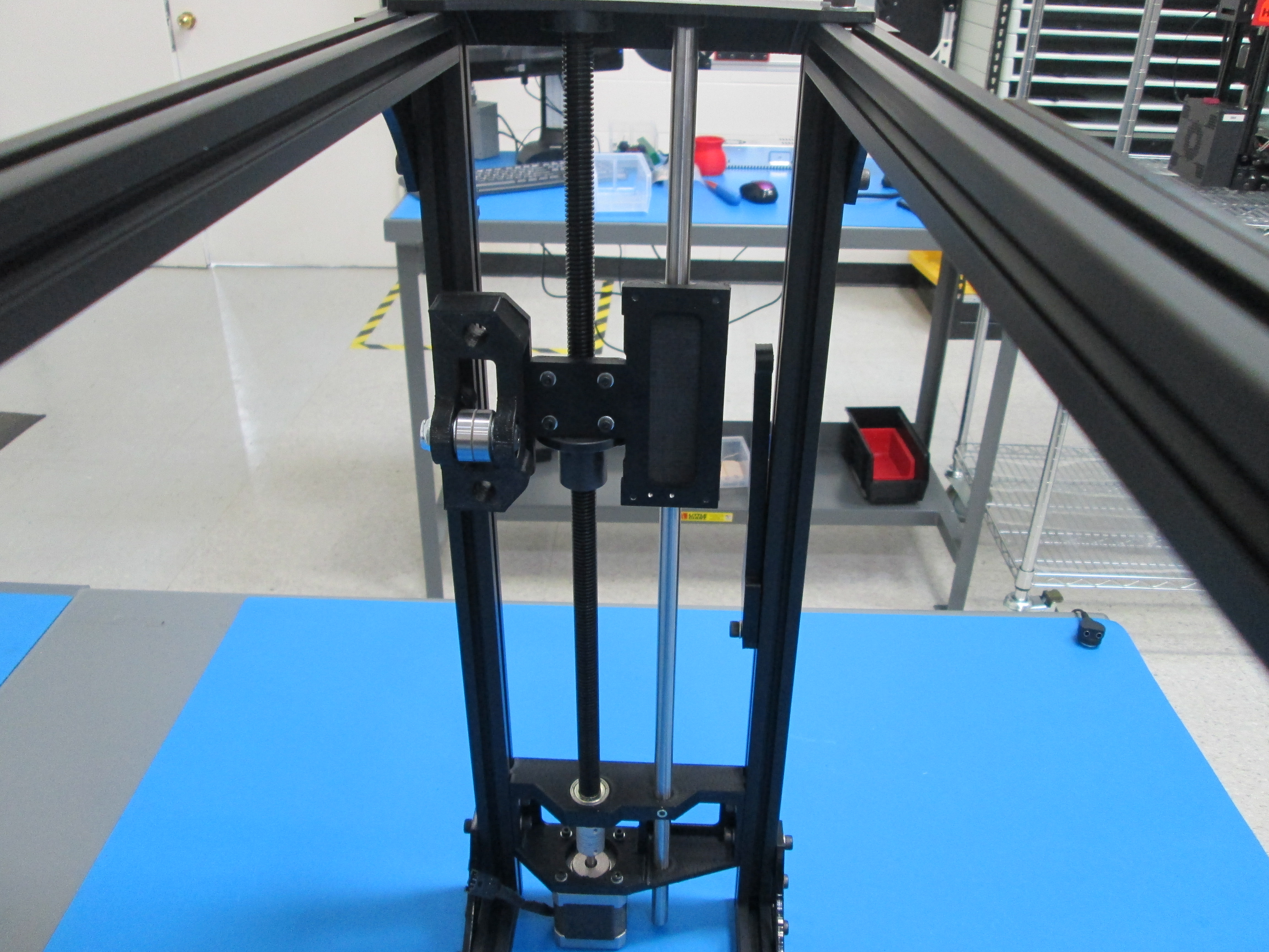
Use 4x M3x12 SHCS with M3 washers to attach the X end motor sub assembly to the Z nut mount as shown.
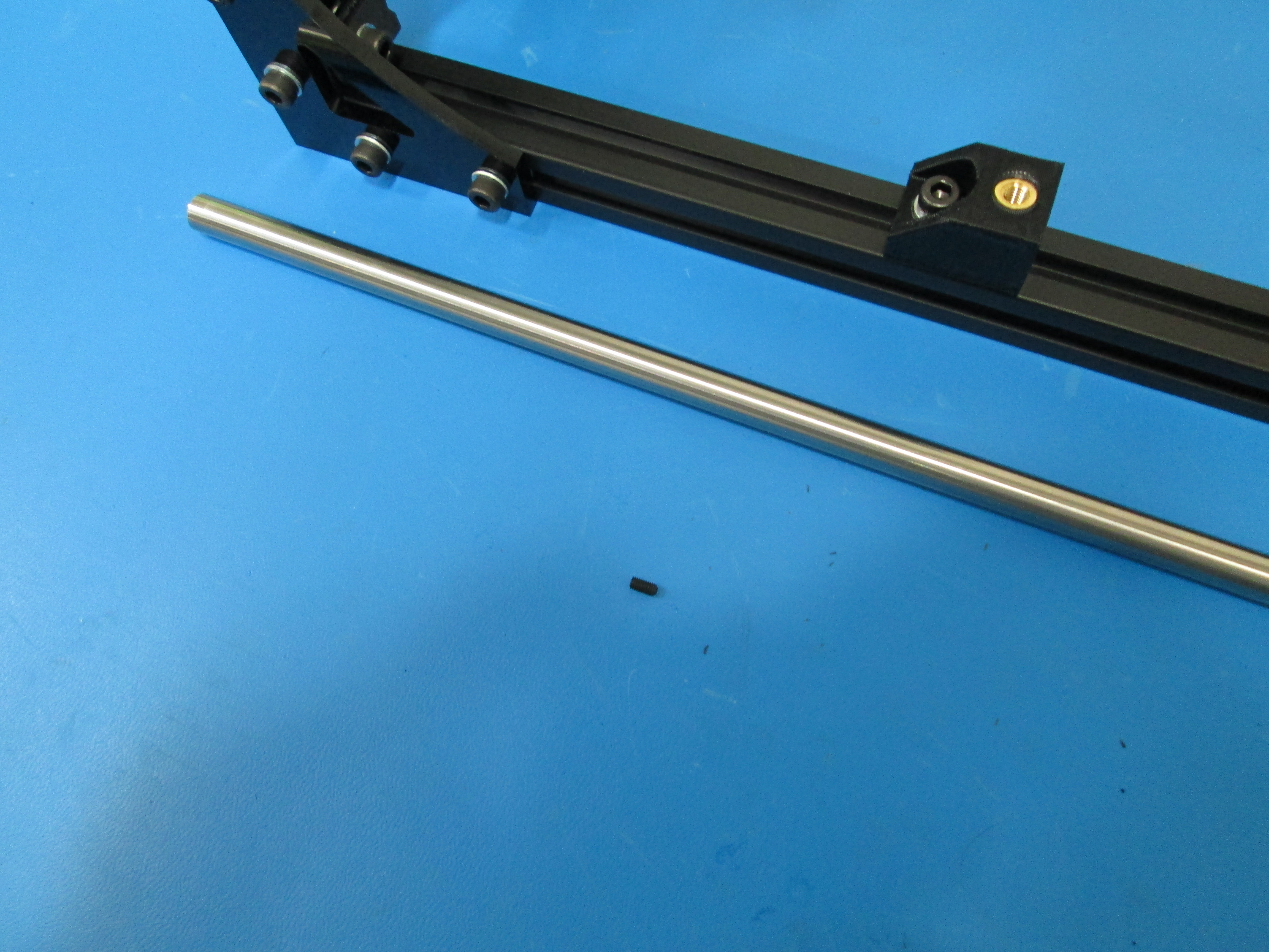
Slide the 10x500mm smooth rod down through the Z top, make sure the smooth rod is flush with the Z top.
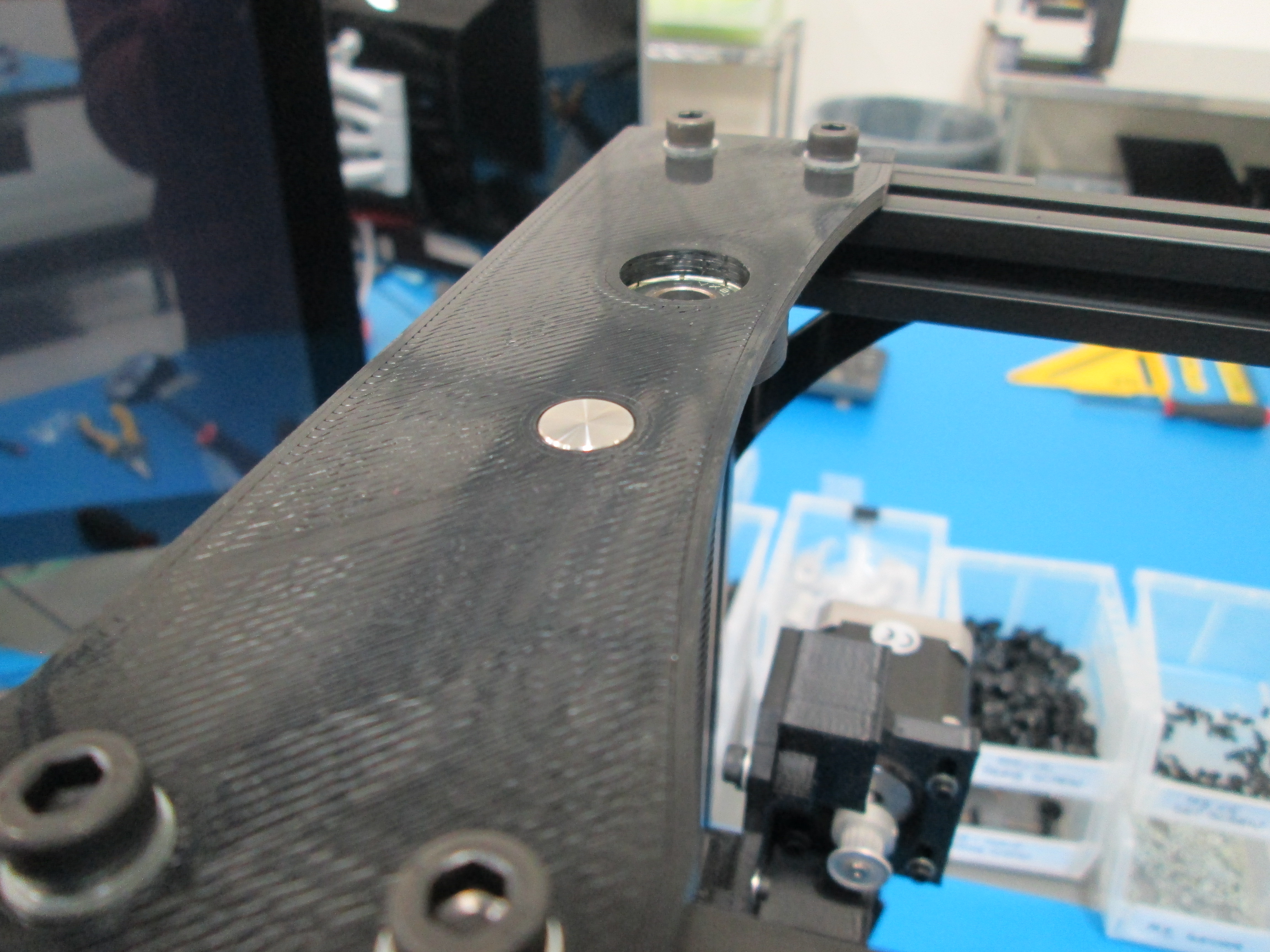
Use M3x6 set screw to secure the smooth rod.
Tighten the 4 bearing holder bolts.
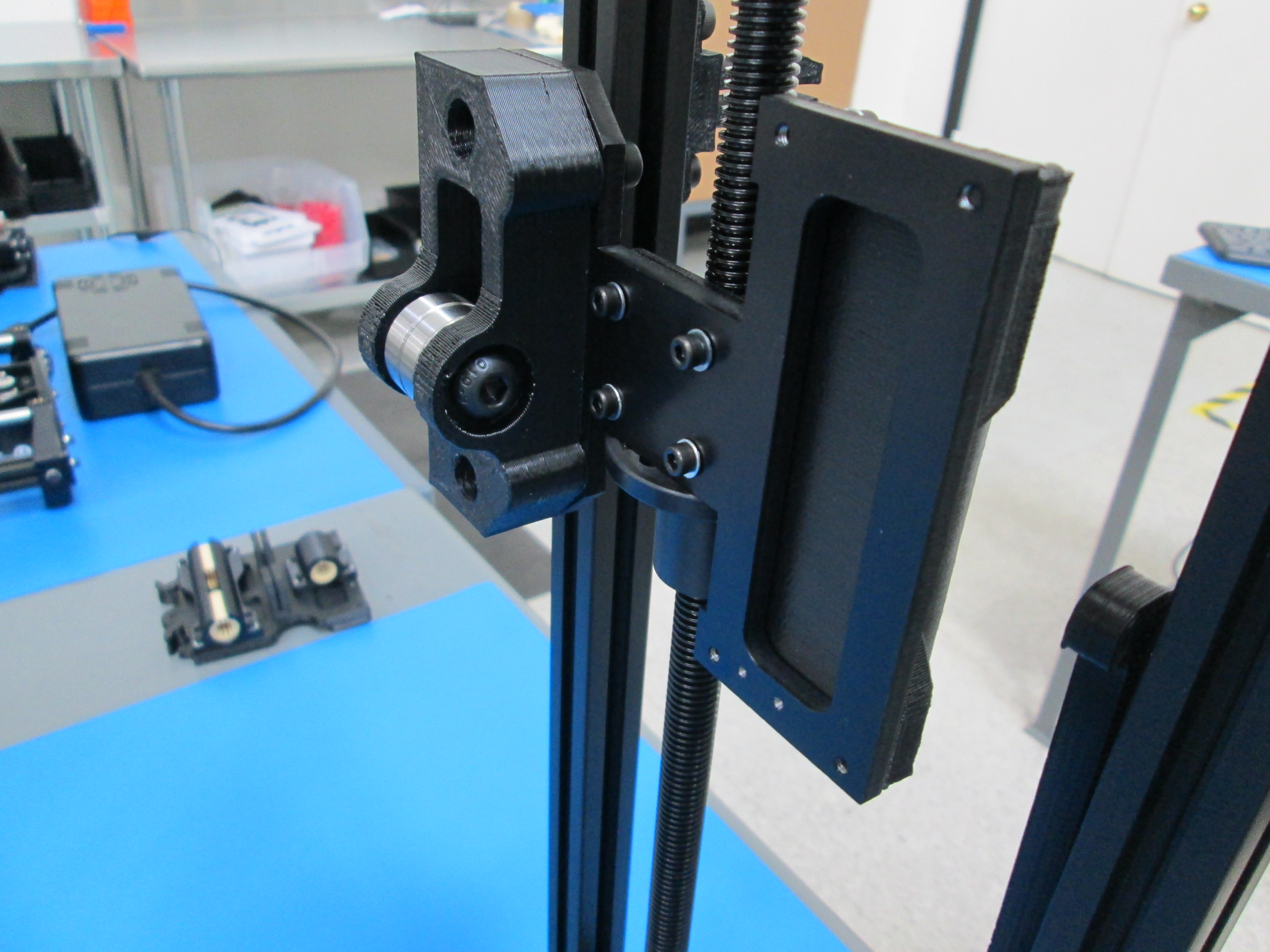
Use 4x M3x12 SHCS wih M3 washers to attach the X end idler sub assembly to the Z nut mount as shown.
Slide the 10x500mm smooth rod down through the Z top, make sure the smooth rod is flush with the Z top.
Use M3x6 set screw to secure the smooth rod.
Tighten the 4 bearing holder bolts.
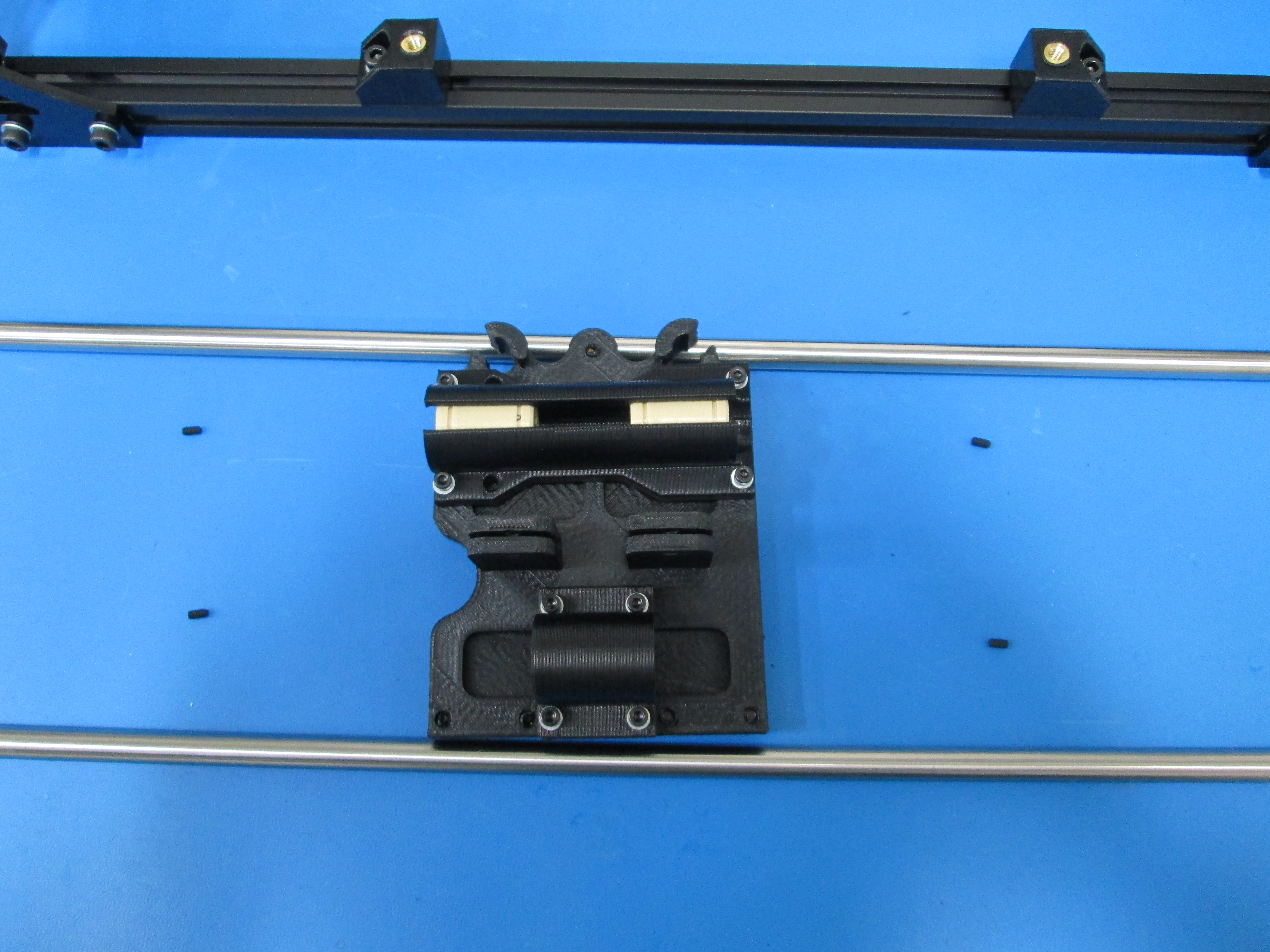
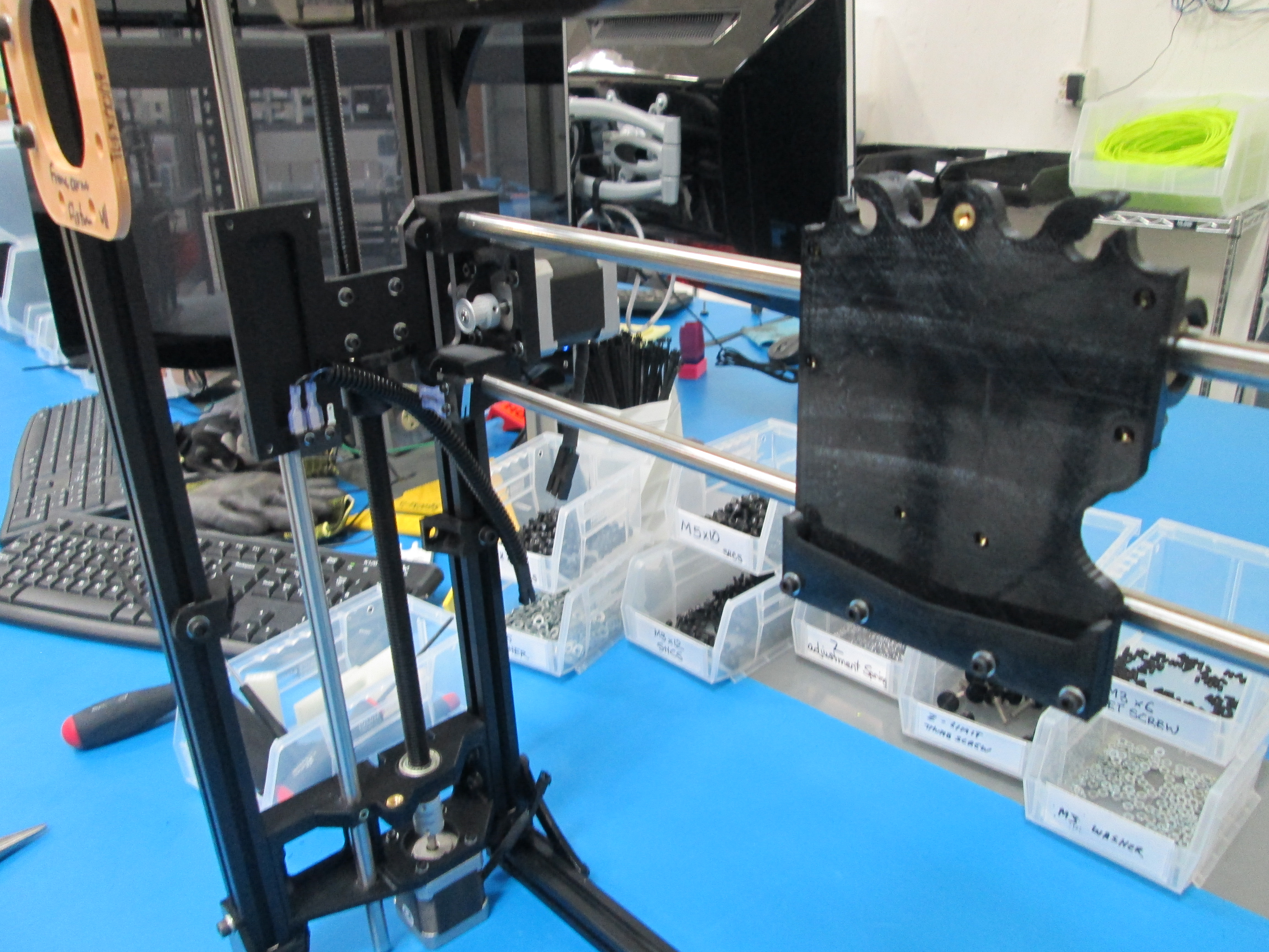
Slide a 10mm rod through one of the two holes in the X end idler.
Once its through far enough, put the X carriage on the rod.
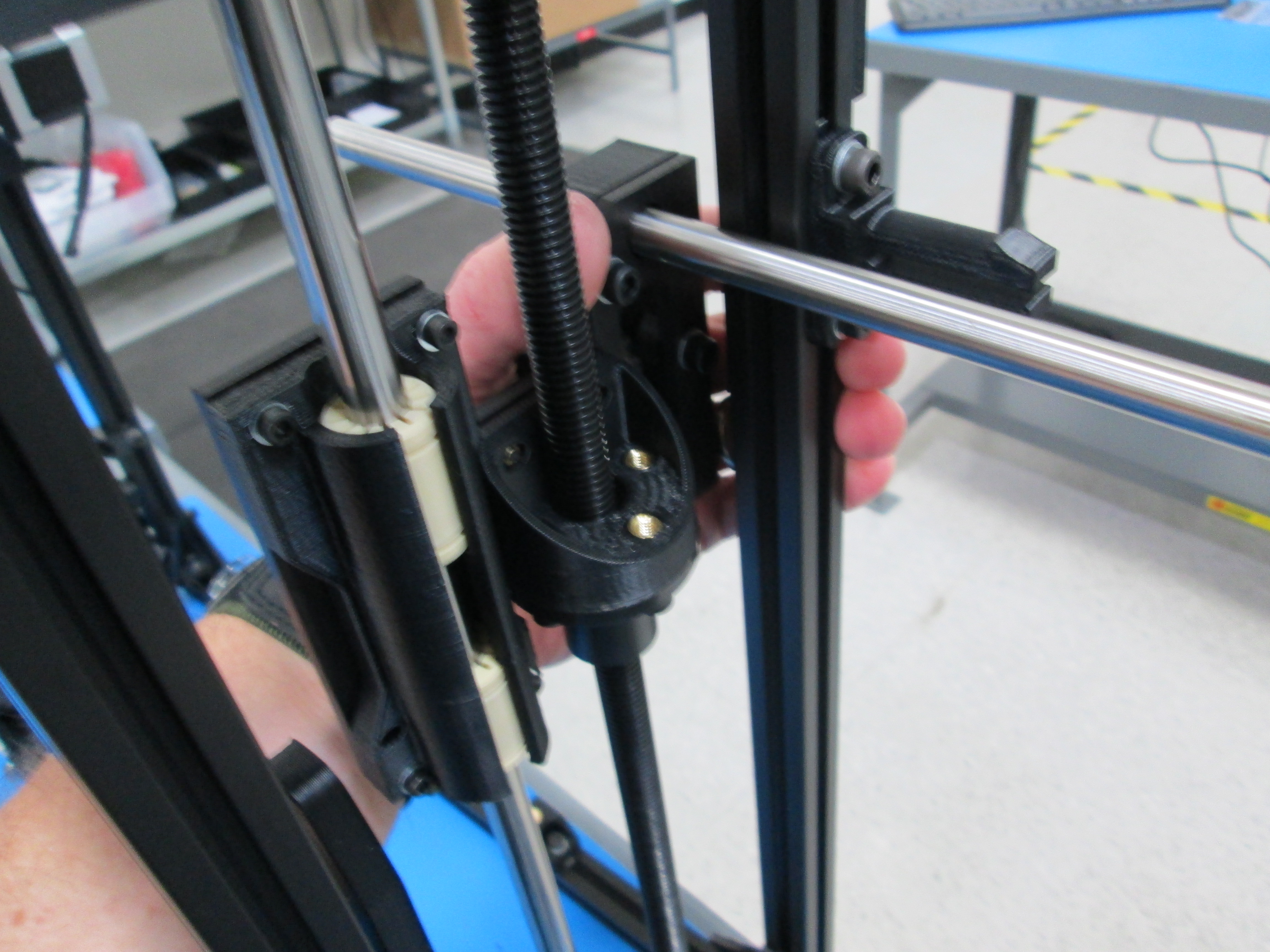
Finish sliding the 10mm rod through until it's also inserted into the X end motor.
The rod will be flush with the outside of the X end motor.
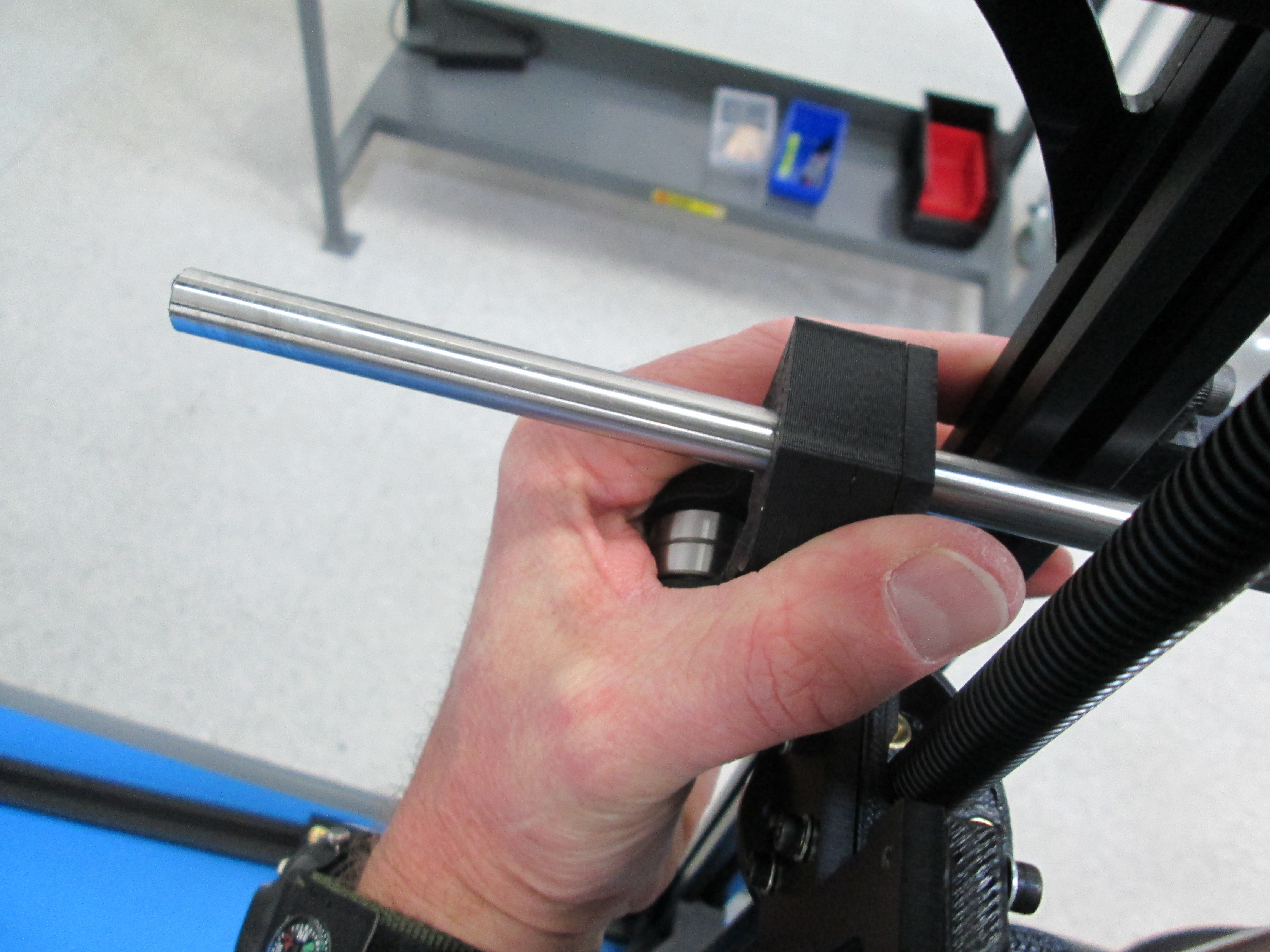
Repeat with the second 10mm rod in the second set of holes.
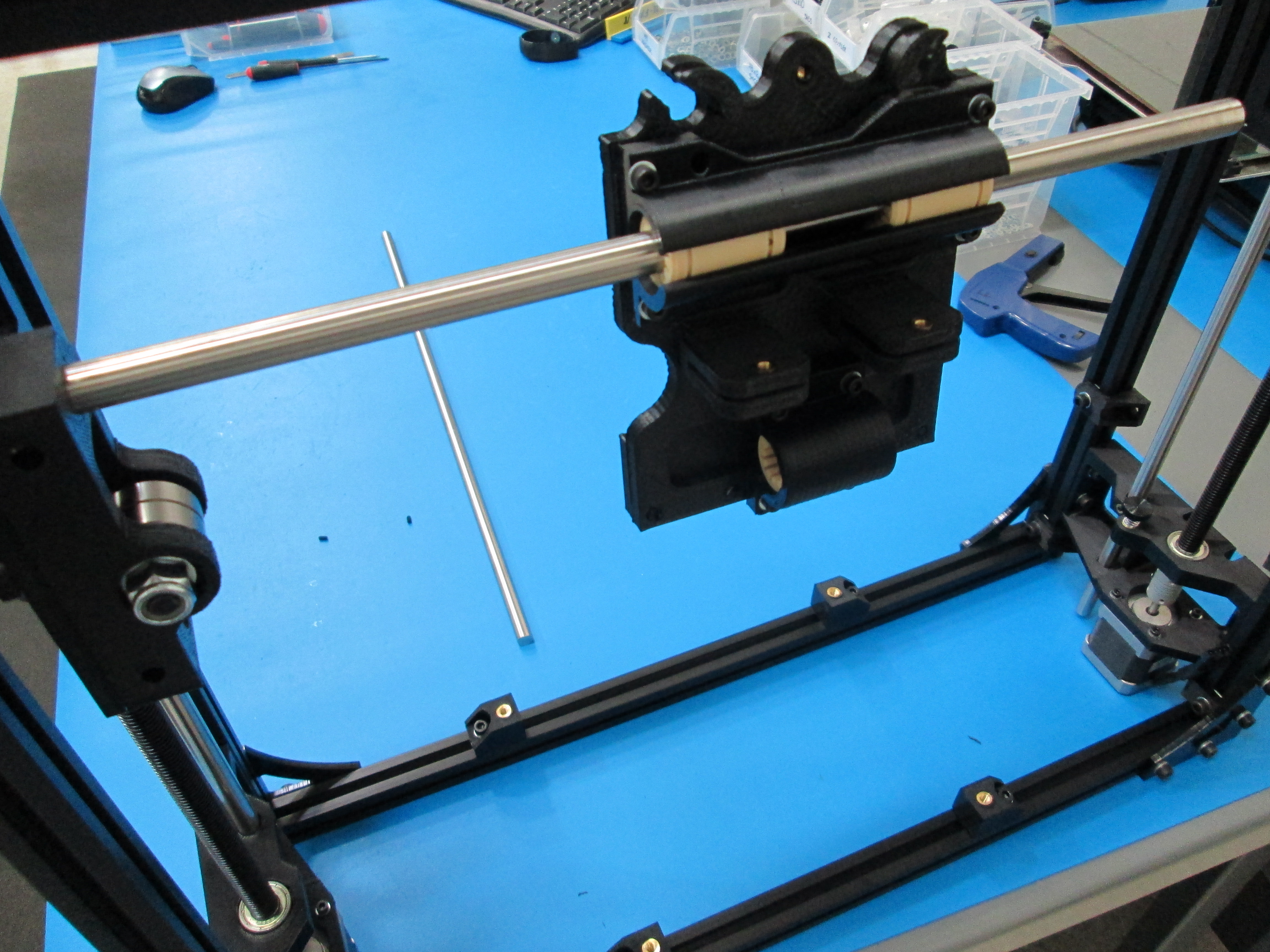
Using 4 M3x6 set screws, lock the rods in place at the X ends.
Tighten the bolts holding the bearing holders on the X carriage making sure it still slides freely back and forth.
Tighten the bolts holding the double bearing holders on the X ends at this point as well.
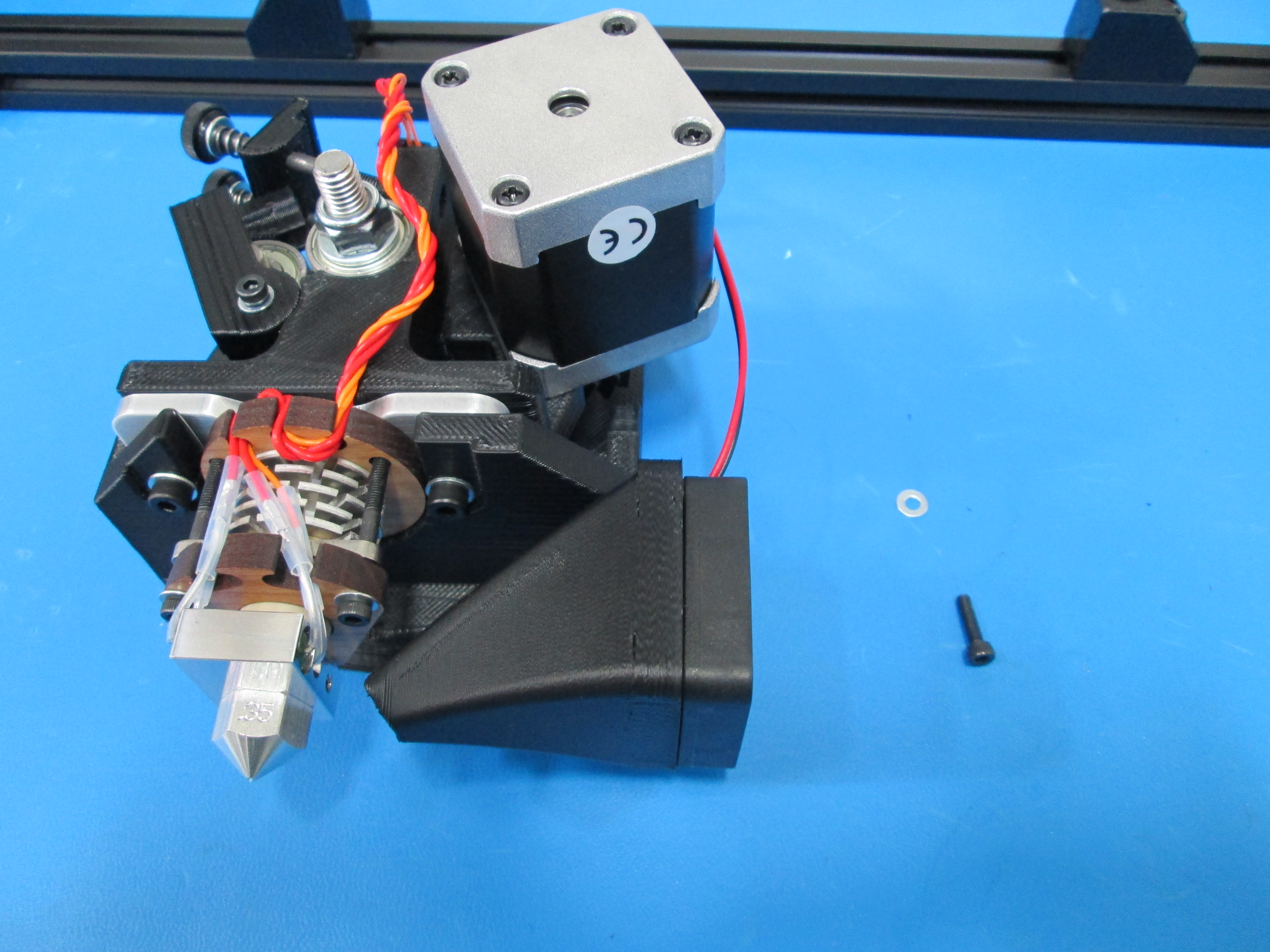
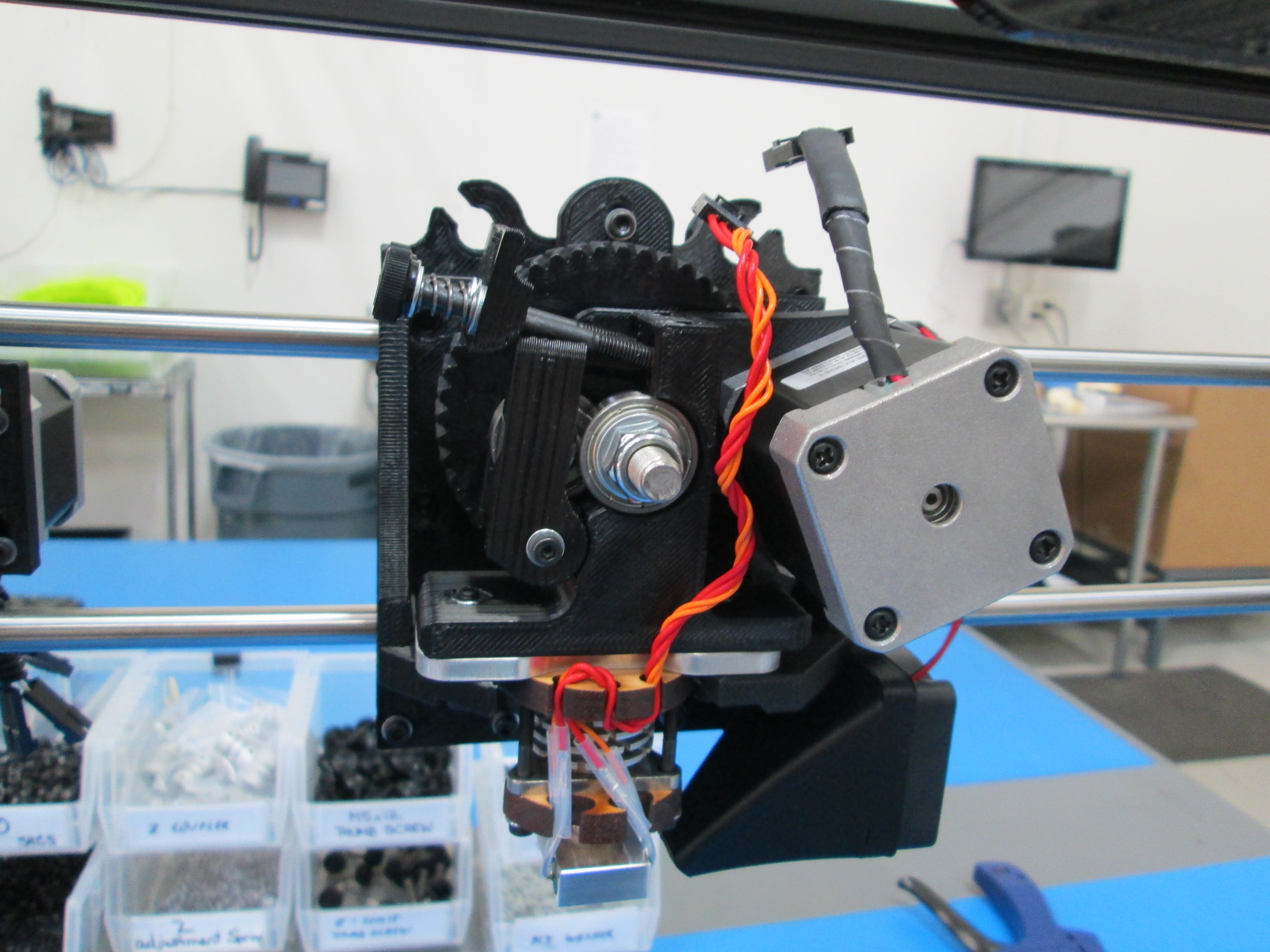
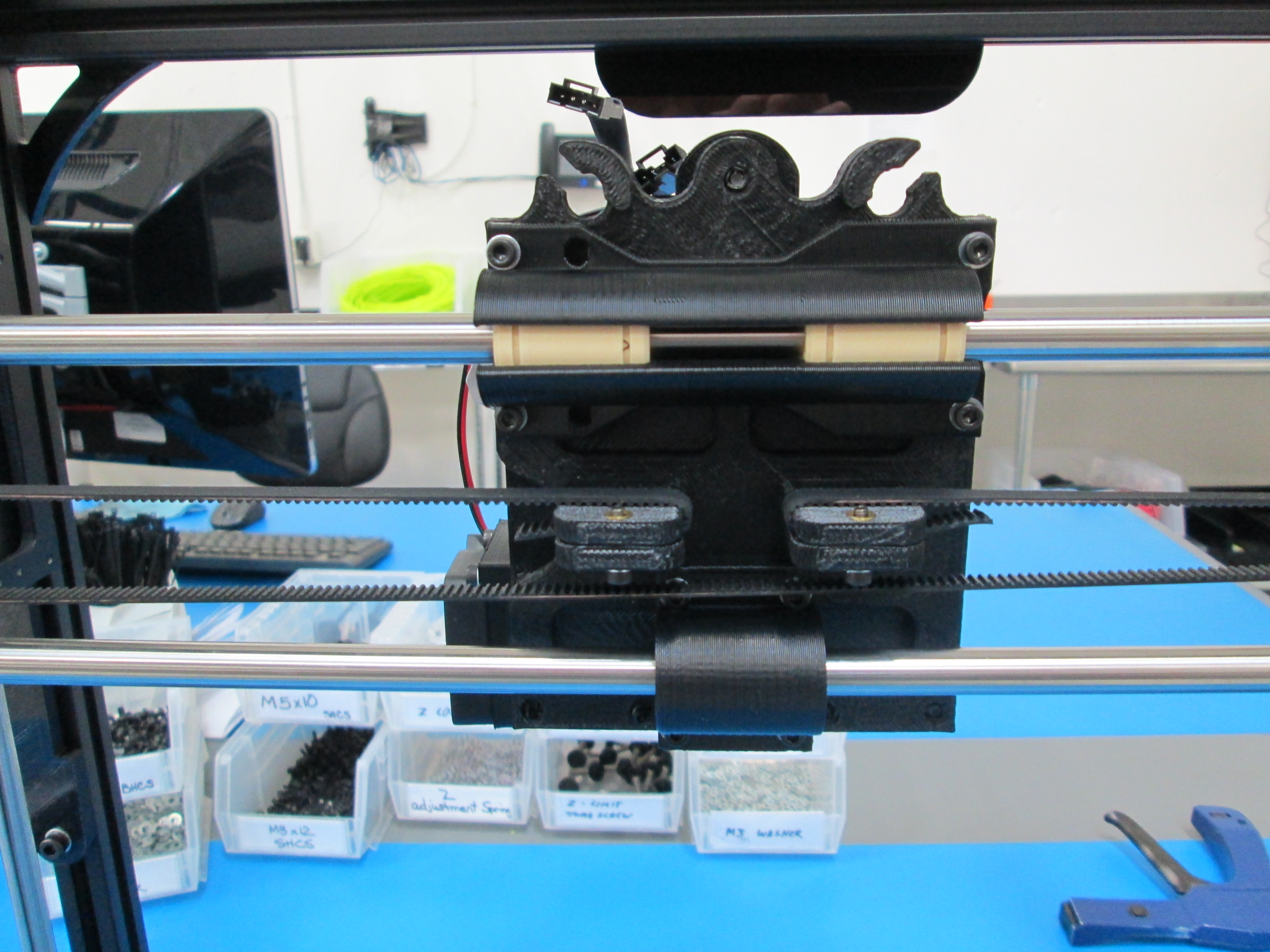
Take the print head assembly and seat the bottom of it down into the X carriage assembly.
Using a M3x12 SHCS and M3 washer, bolt the top of the print head assembly to the X carriage.
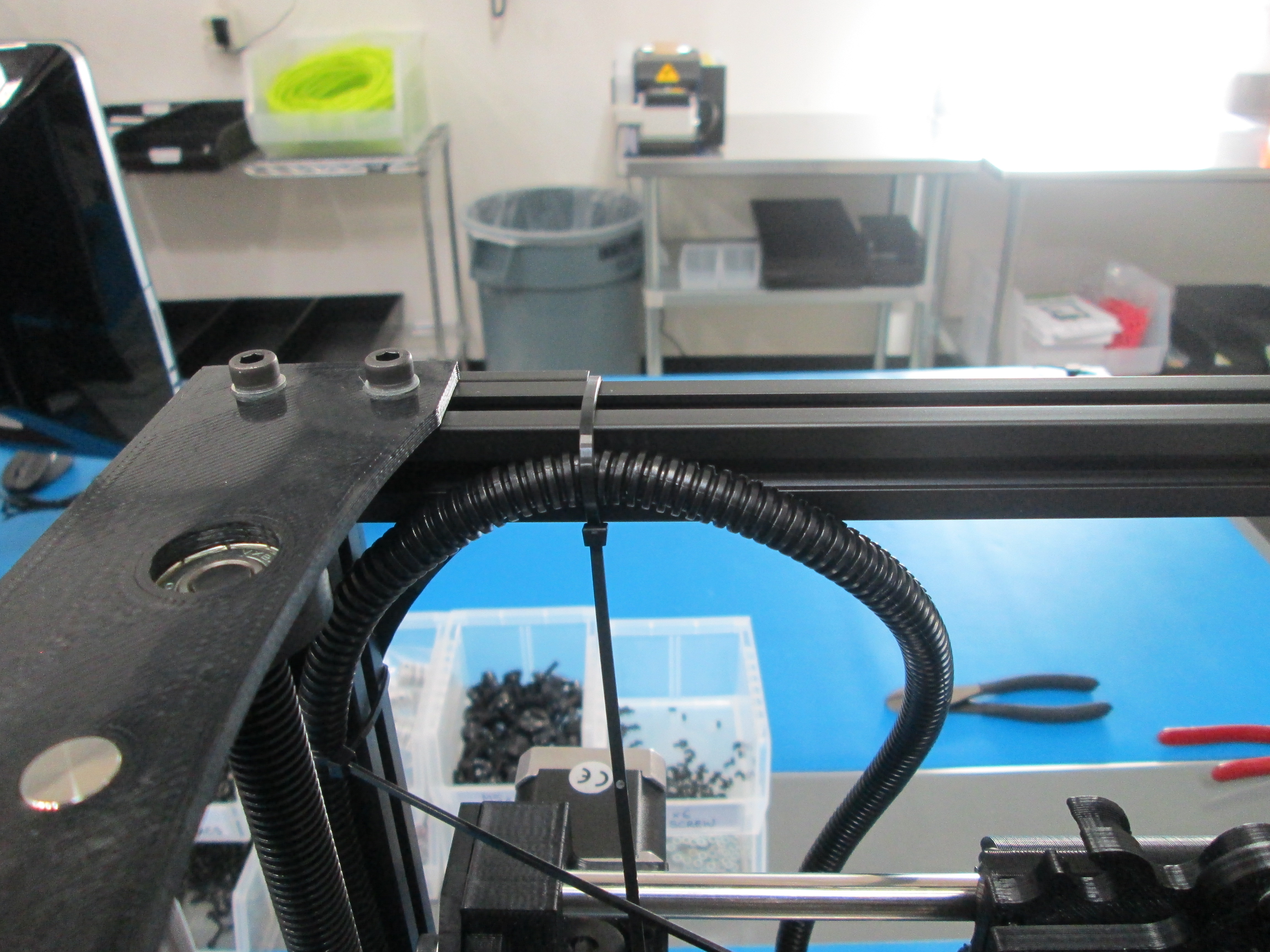
Use the provided 2 zip ties to secure one end of the PTFE feed tube to the Feed Tube Spinner and install it onto the Feed Tube Mount.
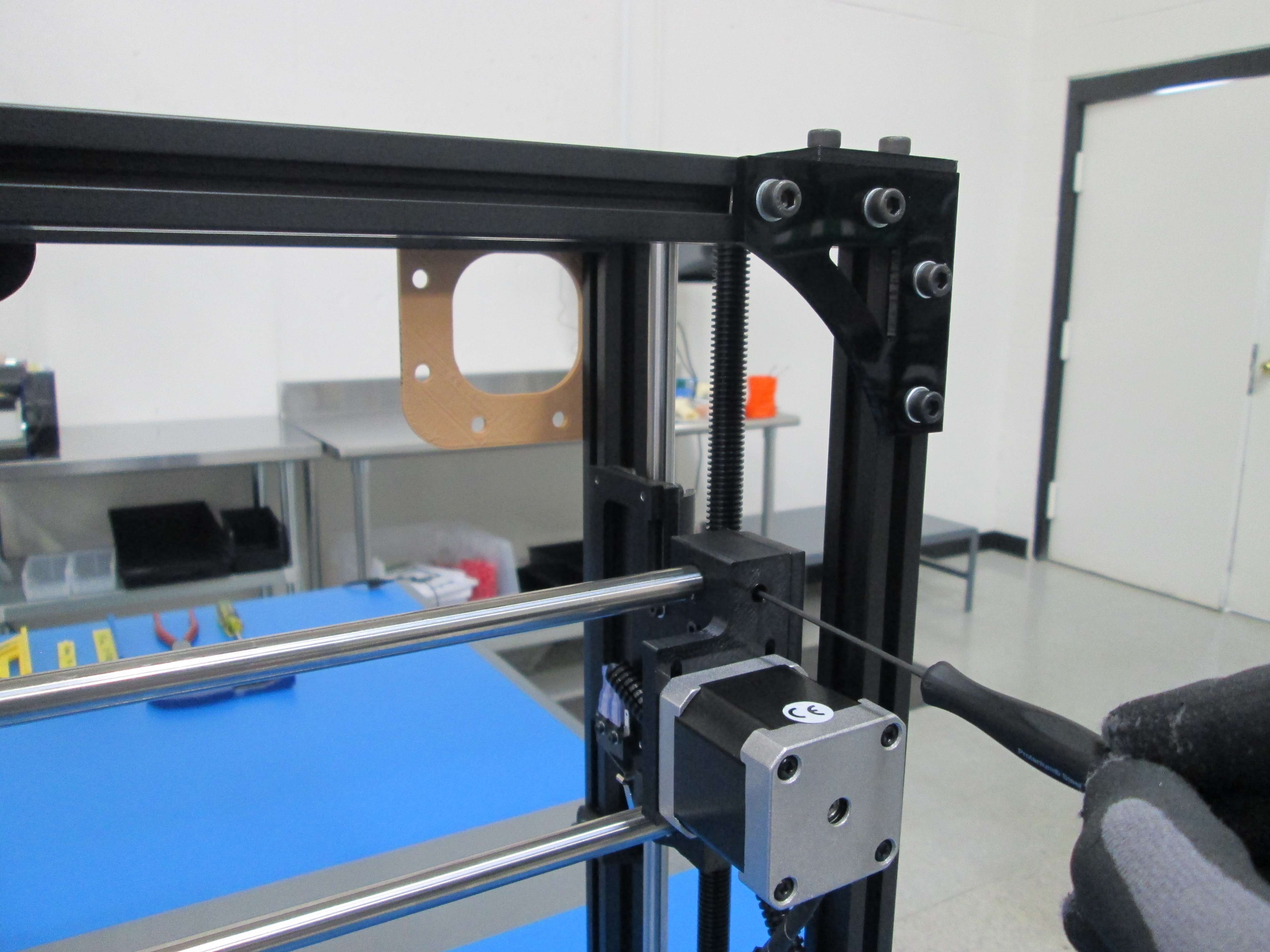
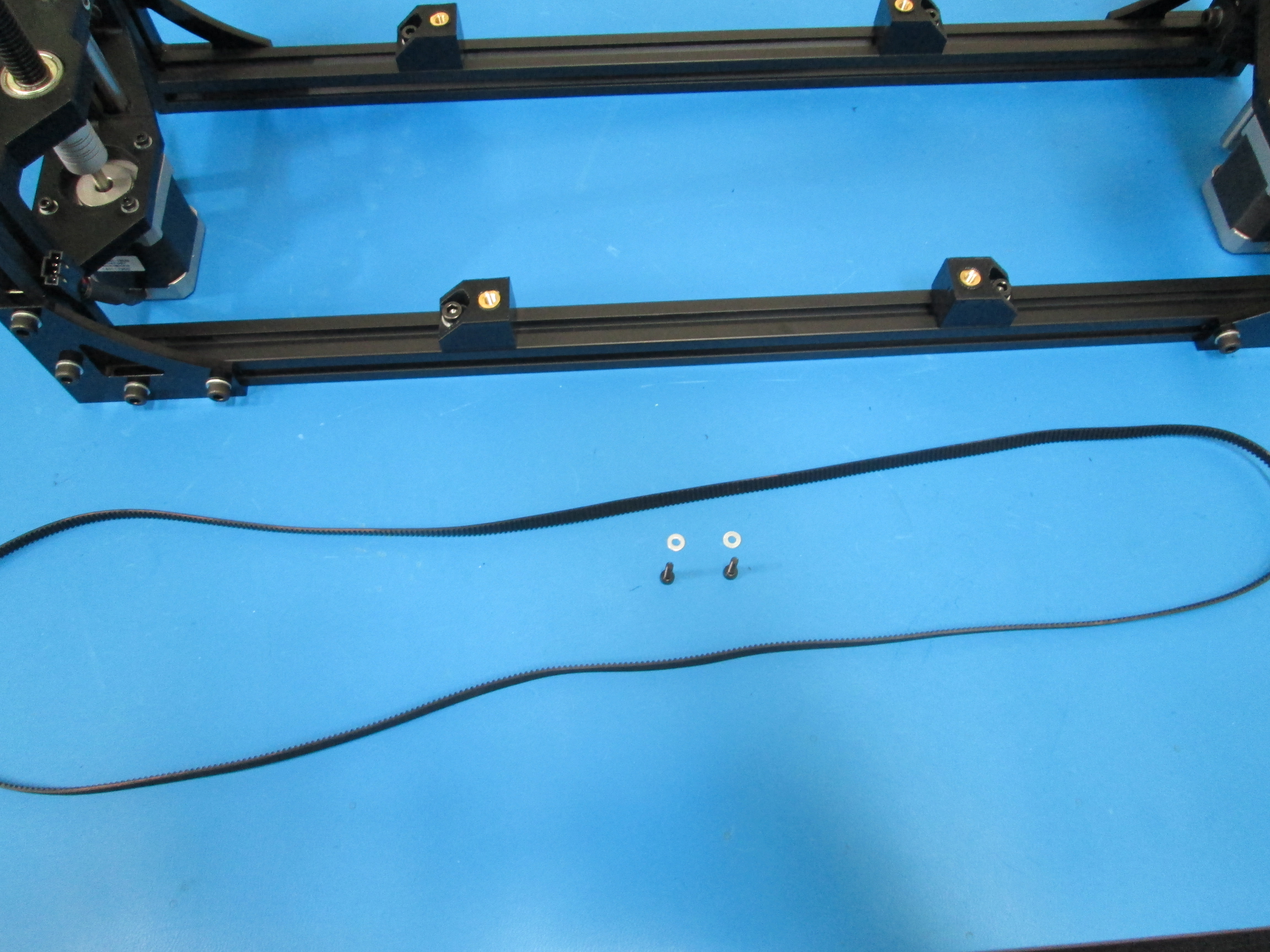
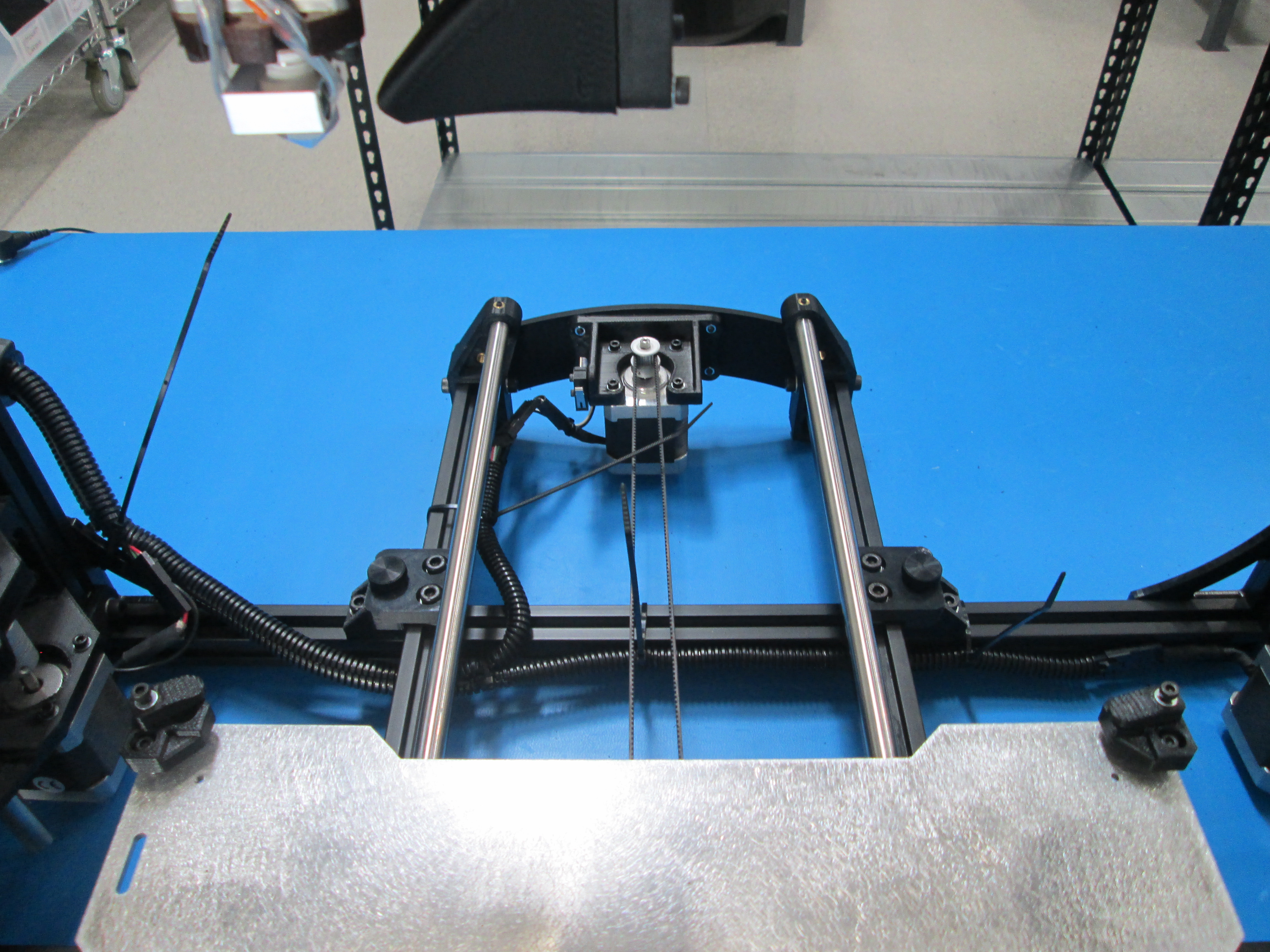
First cut the belt with a side cutters.
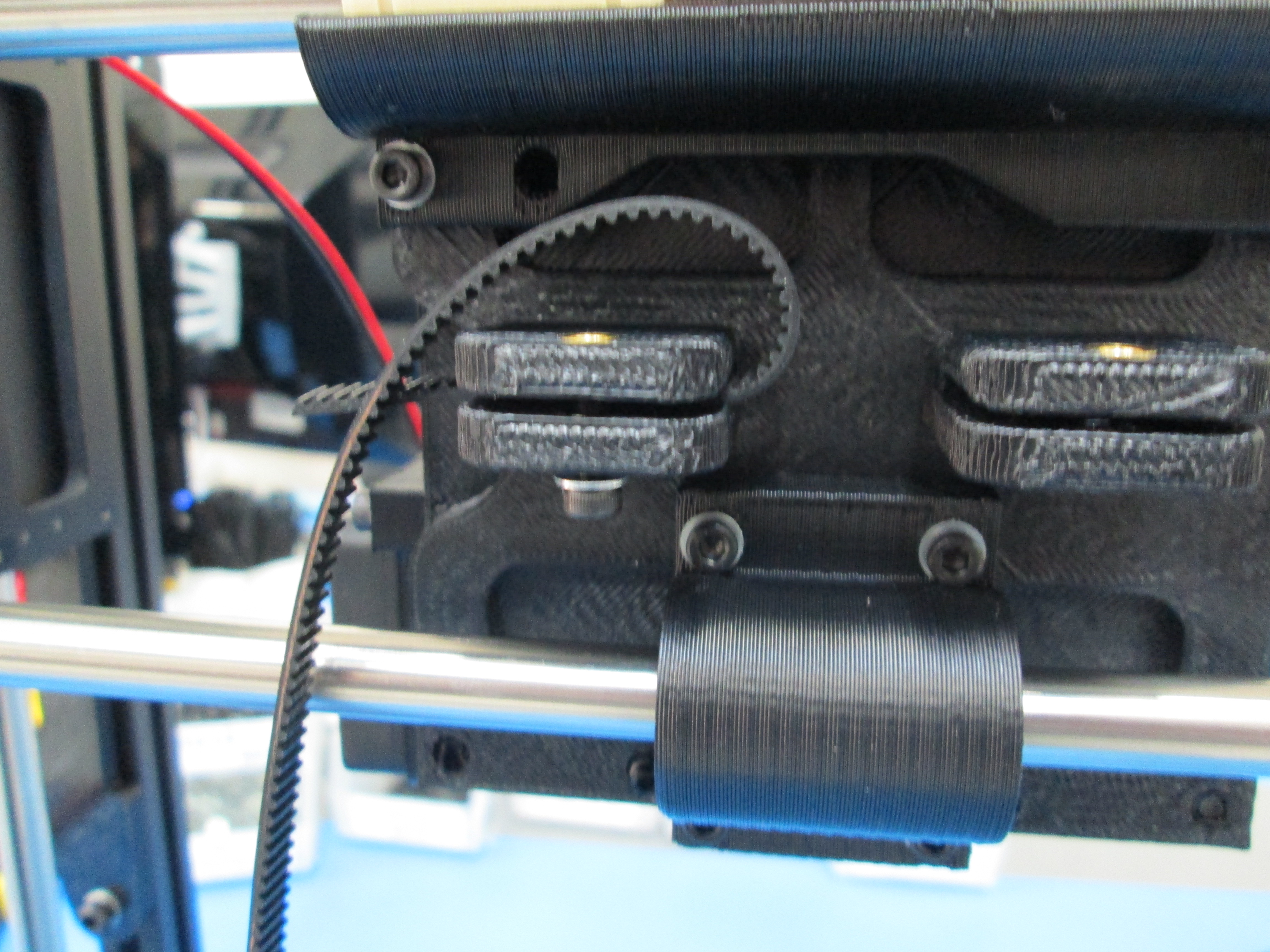
Route one end through the X carriage as shown and clamp down with a M3x12 SHCS and M3 Washer.
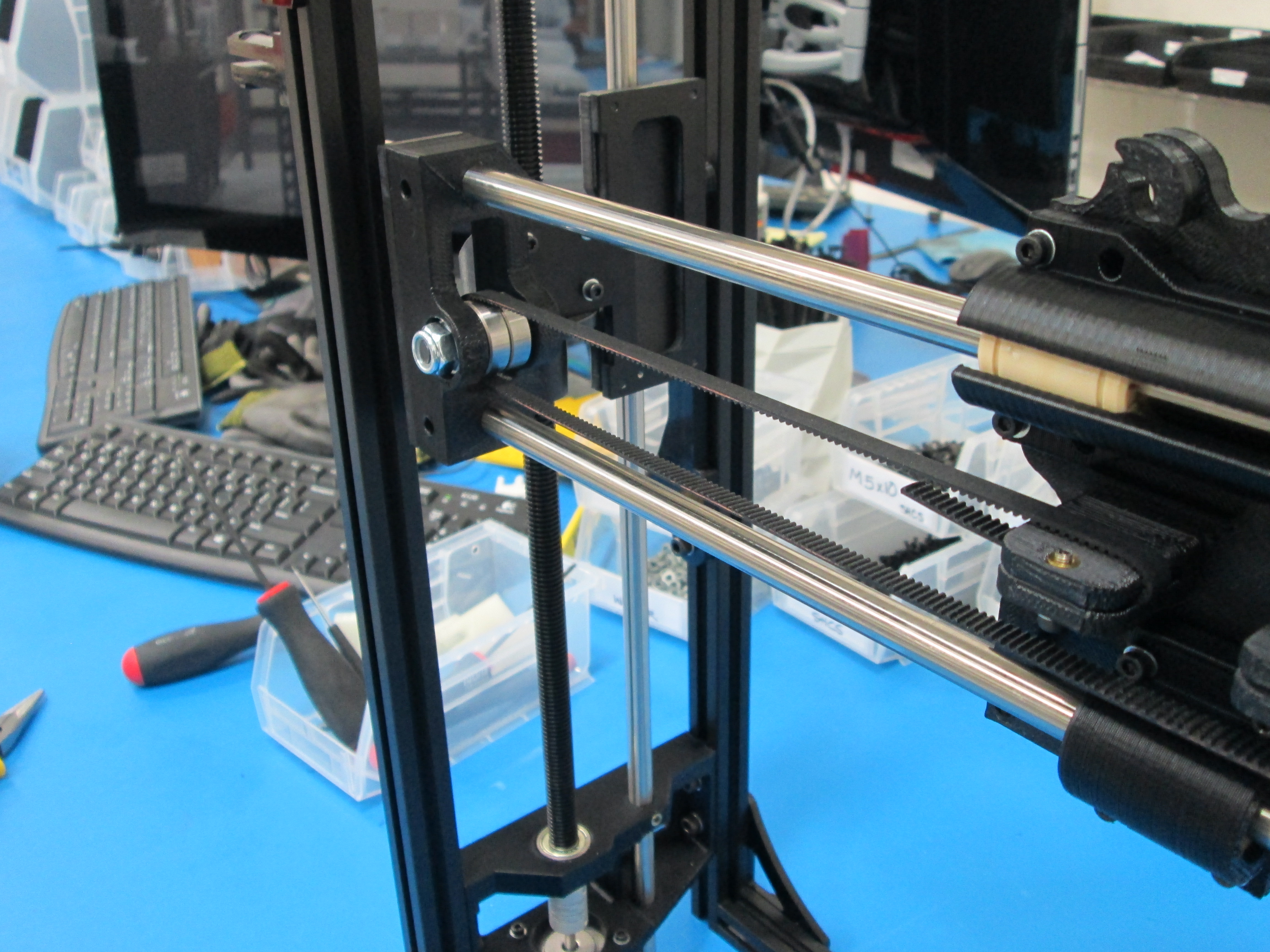
Next route the belt around the pulley on the X end motor and the bearings on the X end idler.
Finish routing the belt back at the X carriage.
Pull tight, with pliers, and clamp down with a M3x12 SHCS and M3 Washer.
Trim the ends of the belt so they do not interfere with the pulley or bearings.
Check for belt rubbing as you move the X carriage back and fourth. Adjust as necessary.
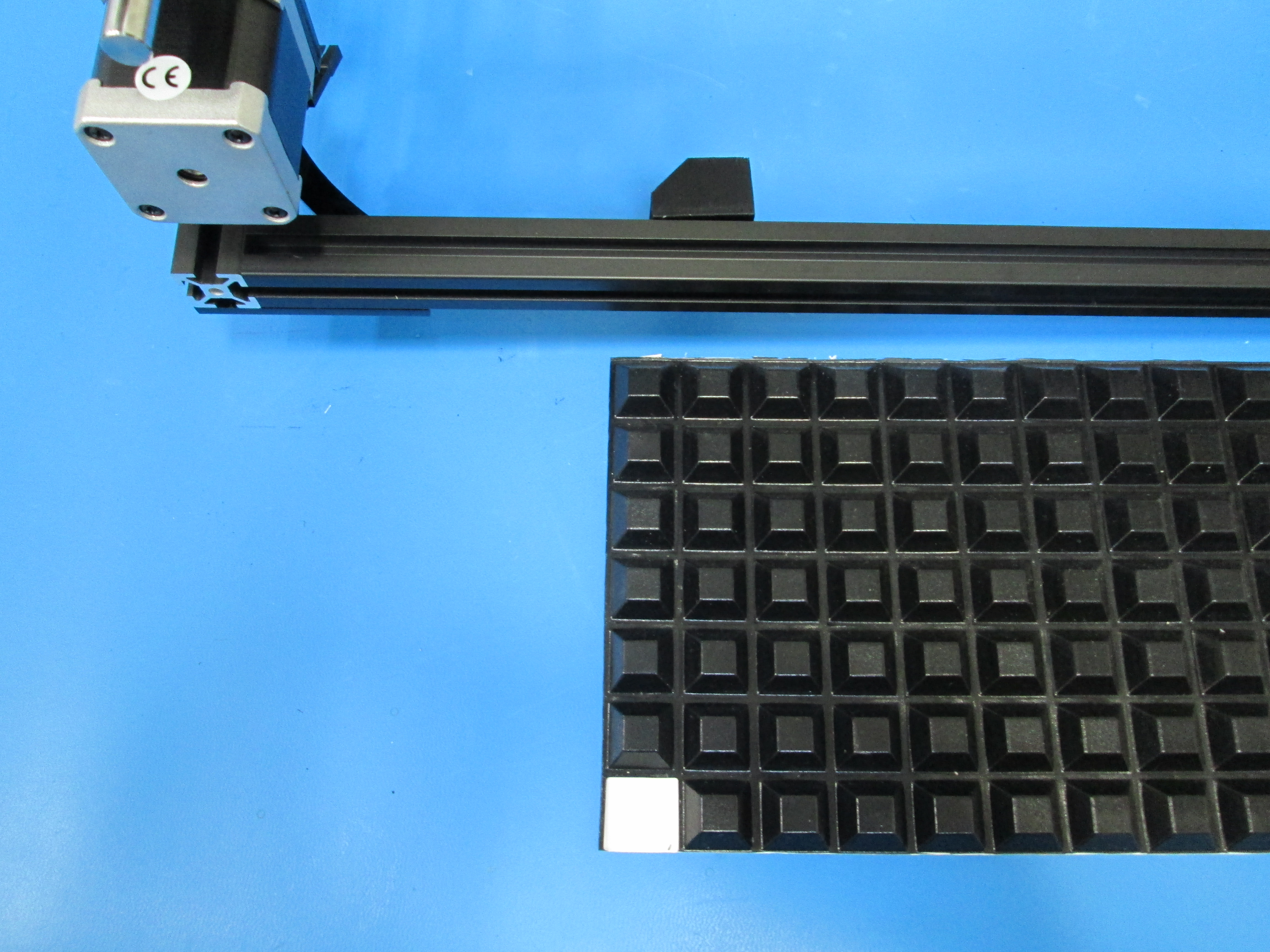
Install 4x rubber feet to bottom of frame.
Take note of location, do not cover bottom of vertical extrusion.
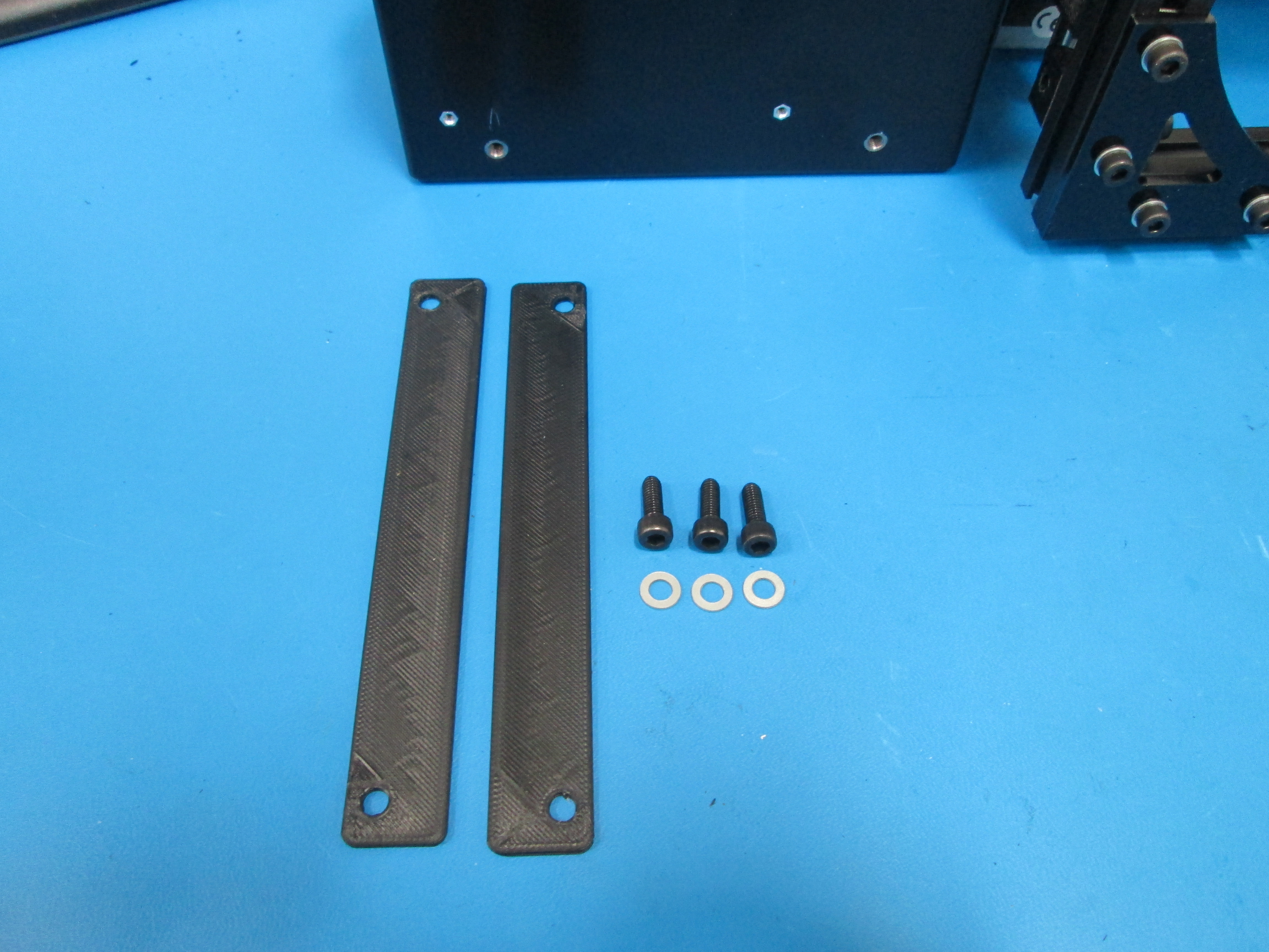
Using 3x M5x14 SHCS and M5 washers, attach the electronics case to the electronics case mounts, make sure to leave out the bottom right bolt for now.
Set the two bottom electronics case mounts flush with the frame. If needed, readjust the top electronics case mounts on the frame.
Your electronics case will not have the connector for the optional Graphical LCD controller addon, or the second extruder connector.
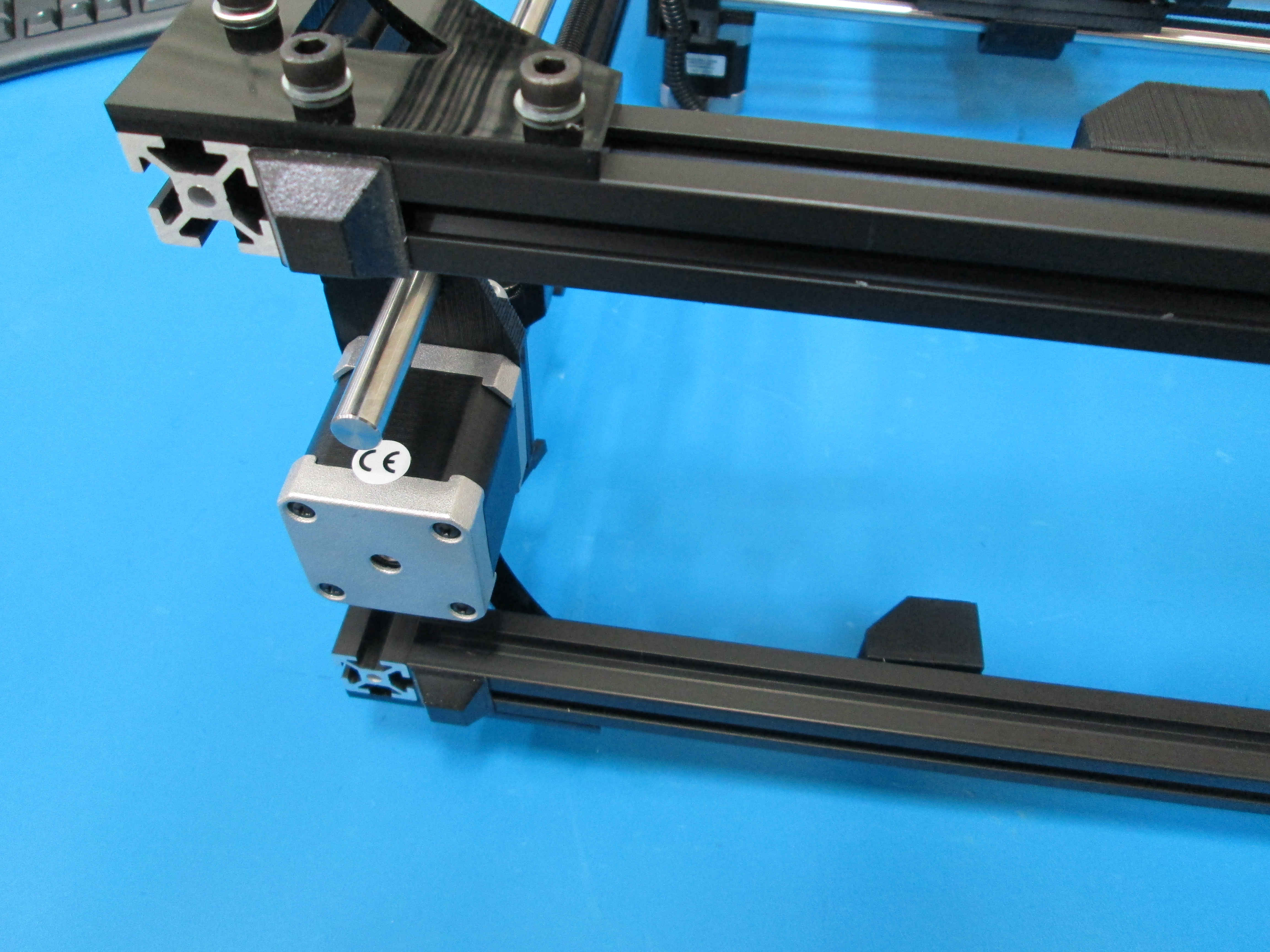
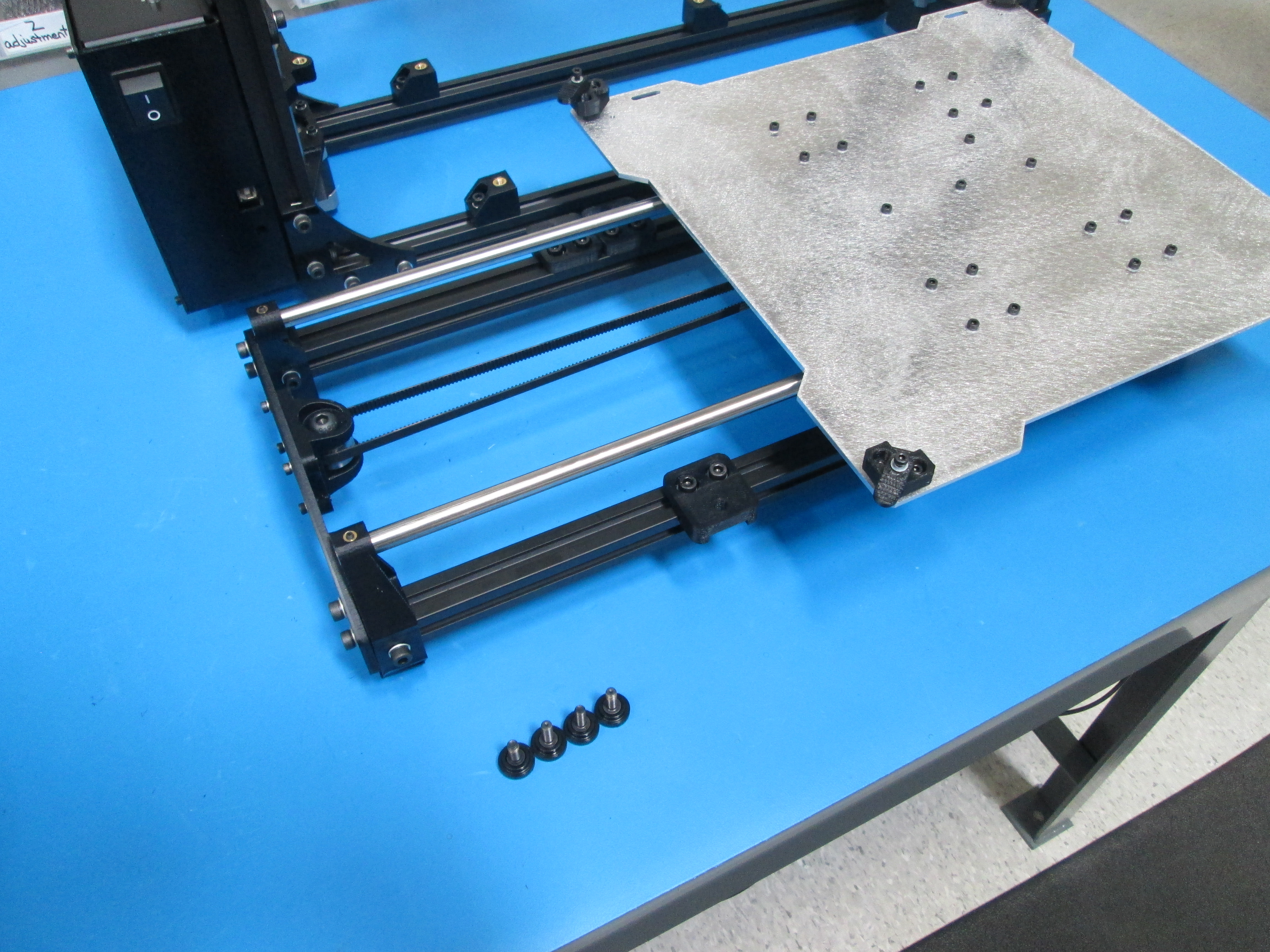
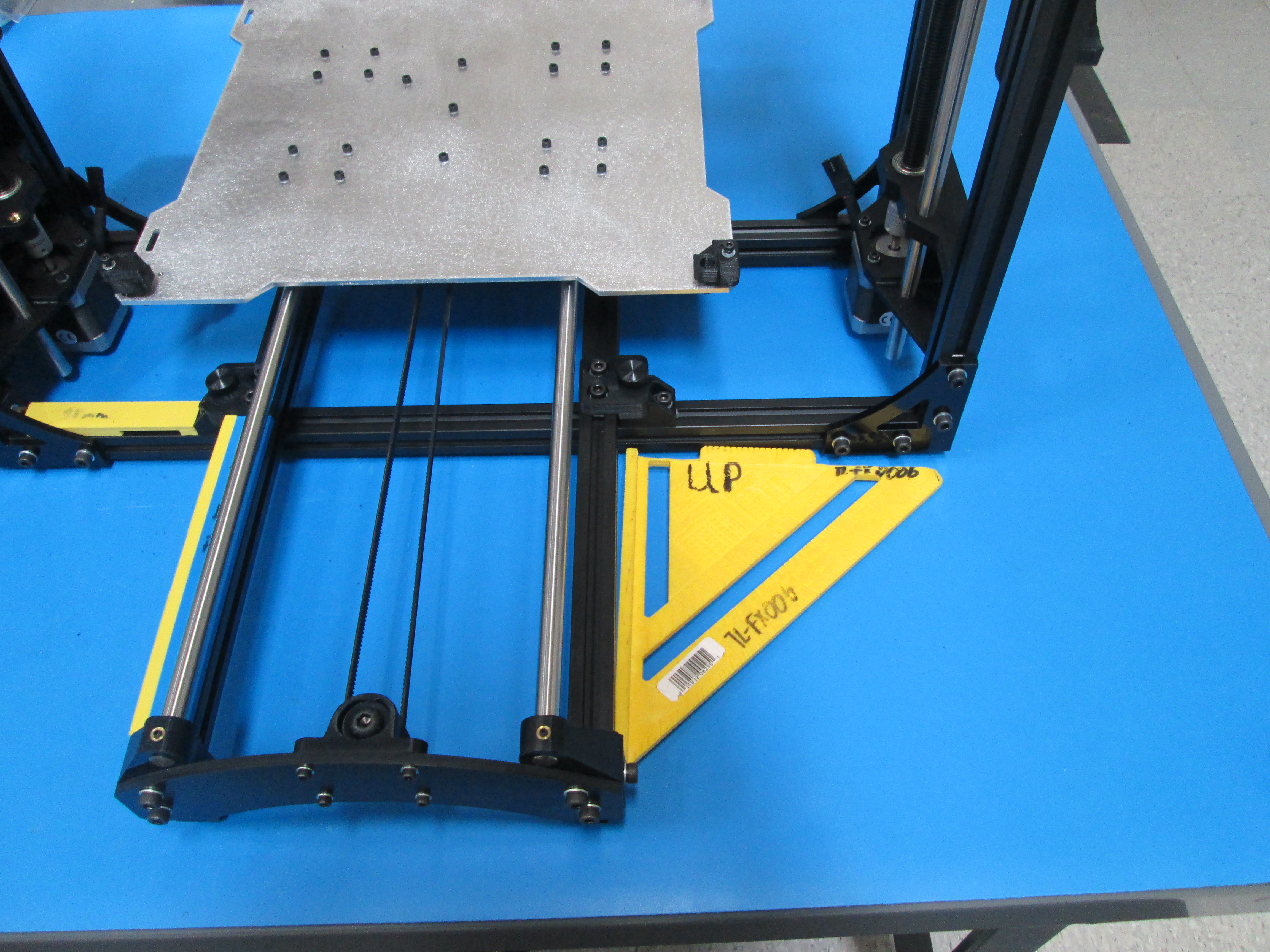
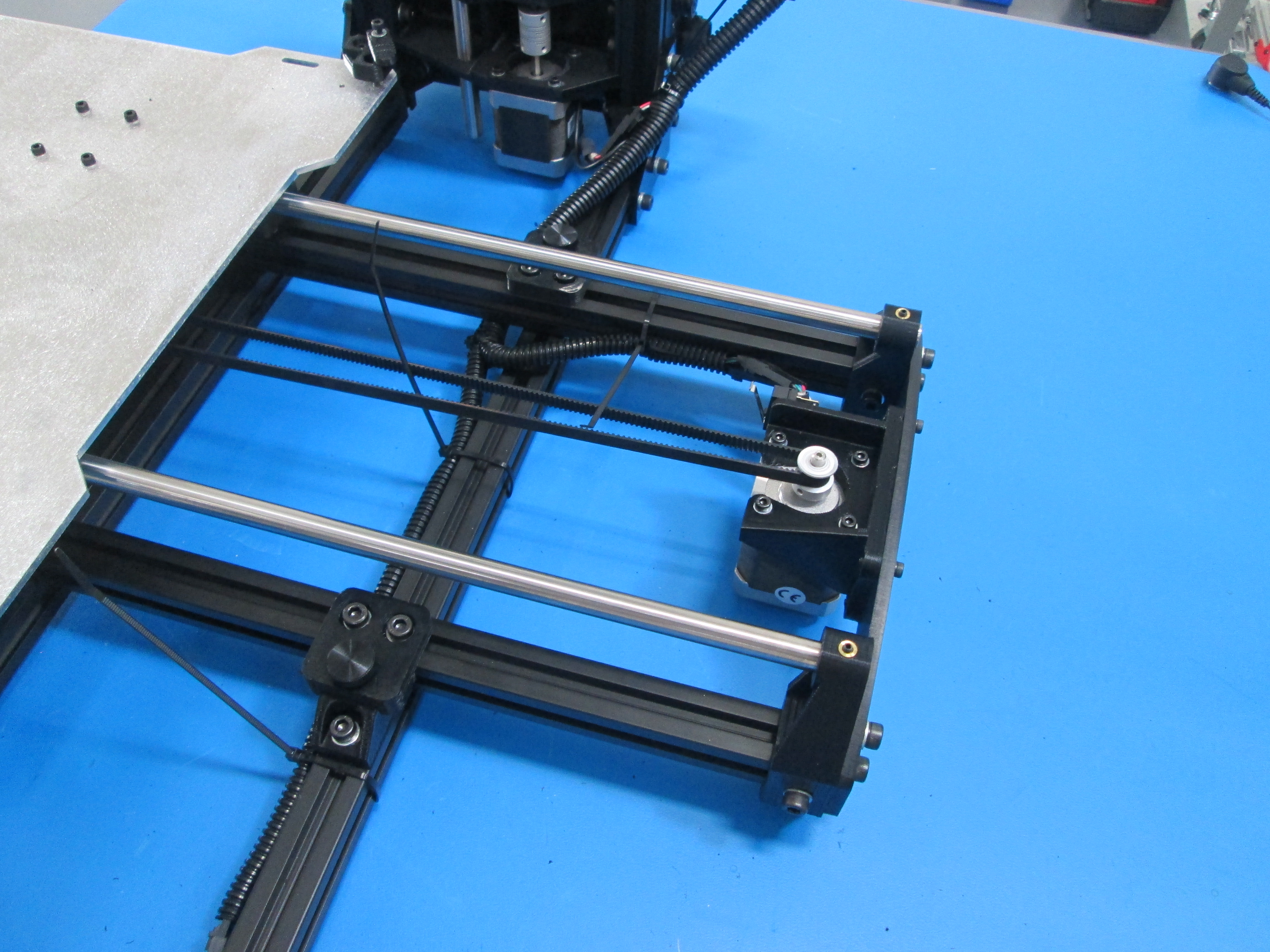
Put 4x rubber feet on the Y axis as shown.
Loosen Y table mounts and Y mount chassis to allow for adjustment.
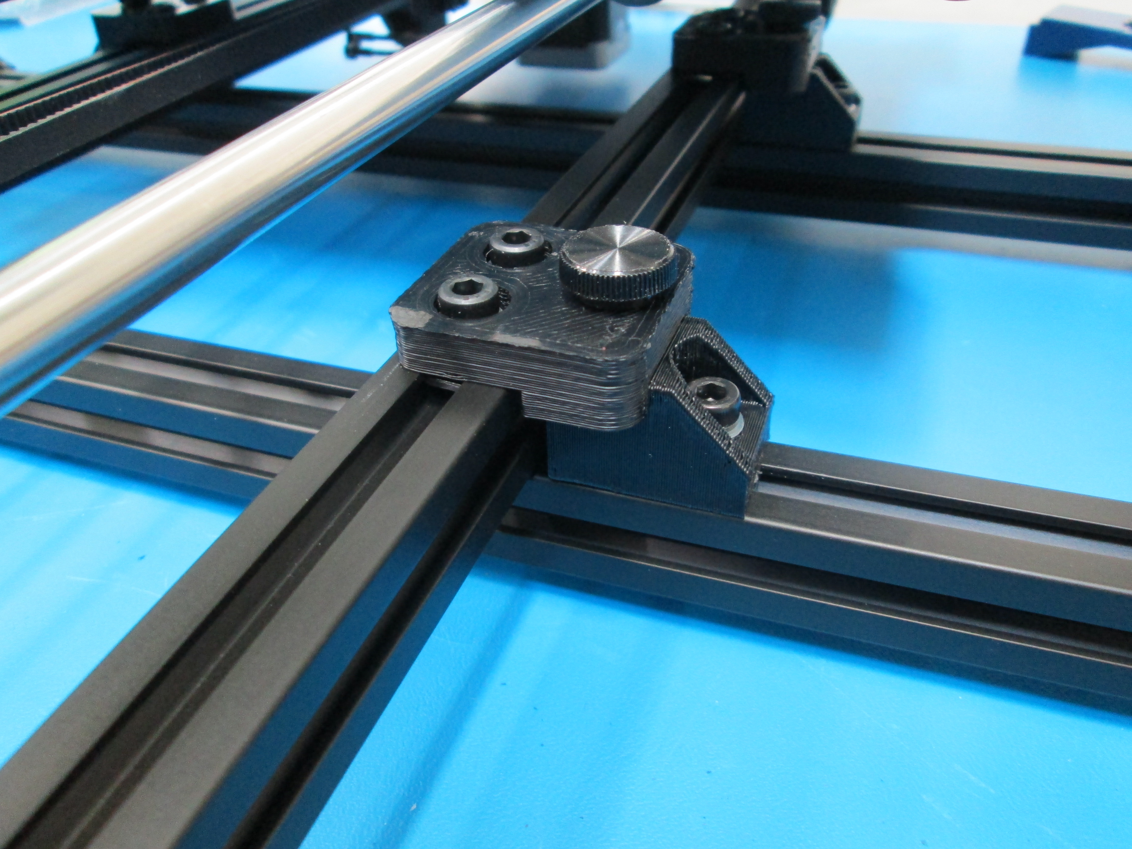
Install 4x M5x14 thumbscrews.
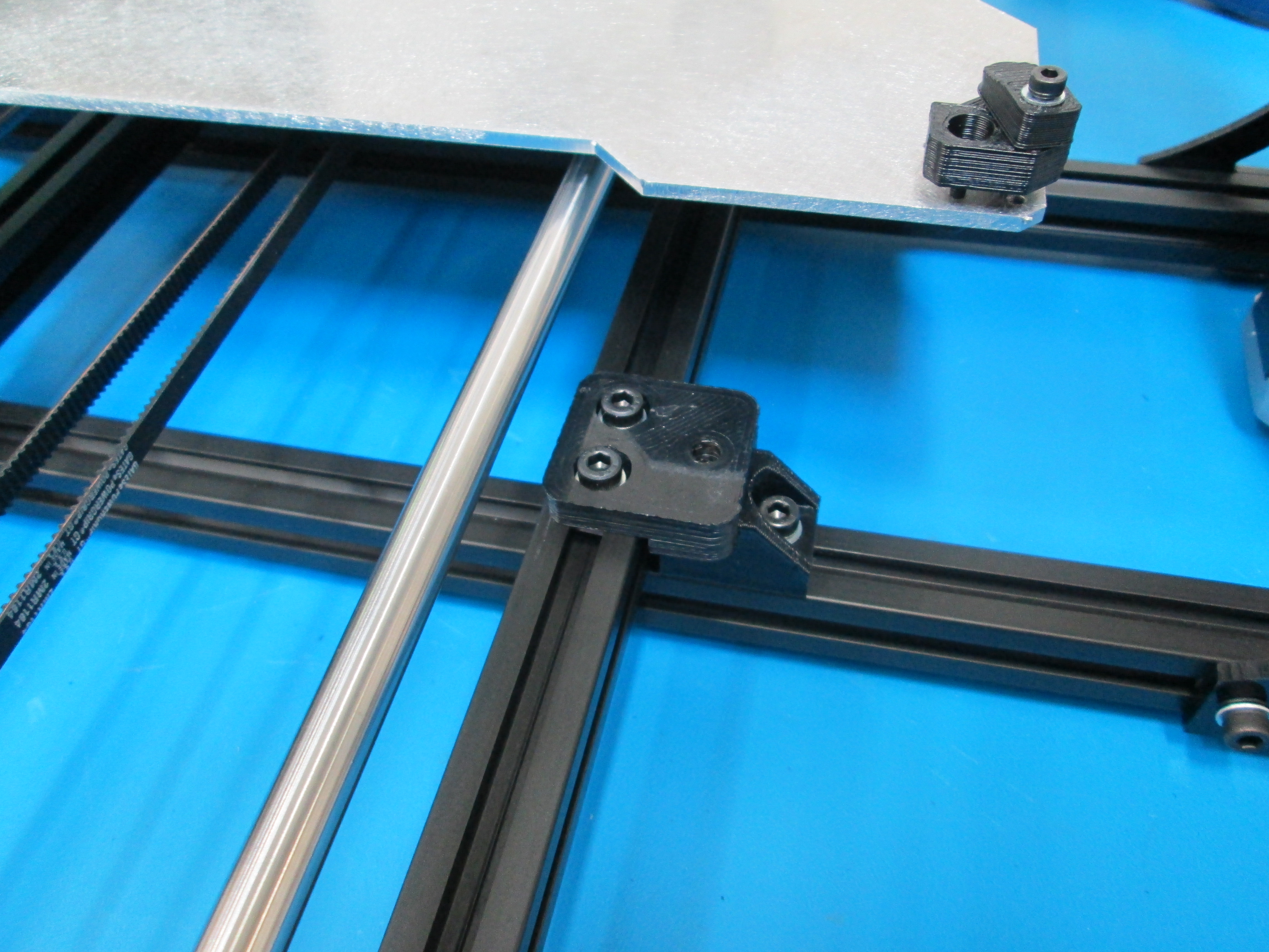
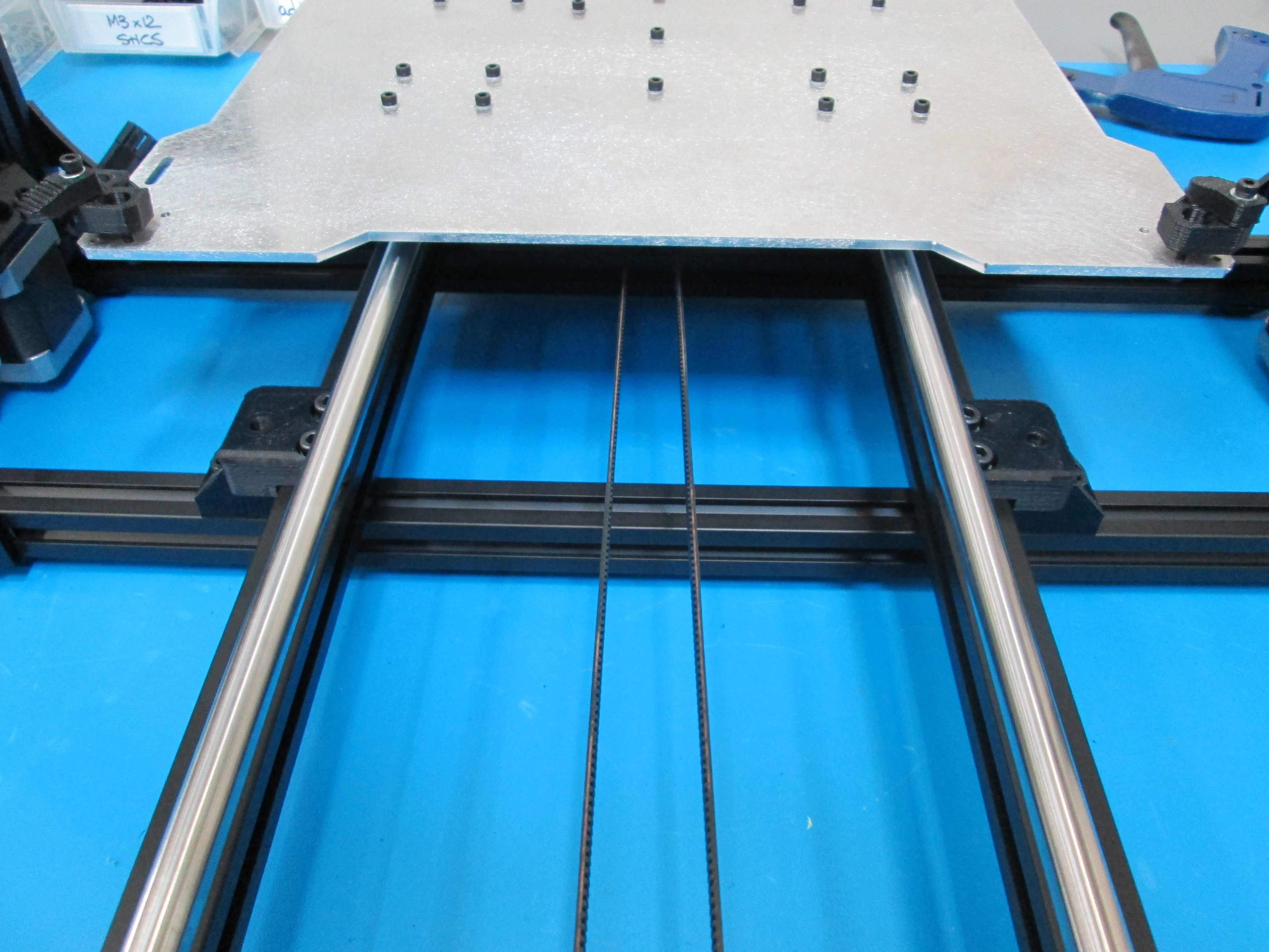
Square frame using fixtures, or set the distances at 110 mm from inside of the left side frame extrusions to the inside of the Y chassis mounts and 163 mm from the Y table mount to the inside of the Y corners.
Tighten Y table mounts, Y mount chassis and thumbscrews.
Make sure Y axis is sitting flush on frame with no gaps in between extrusions.
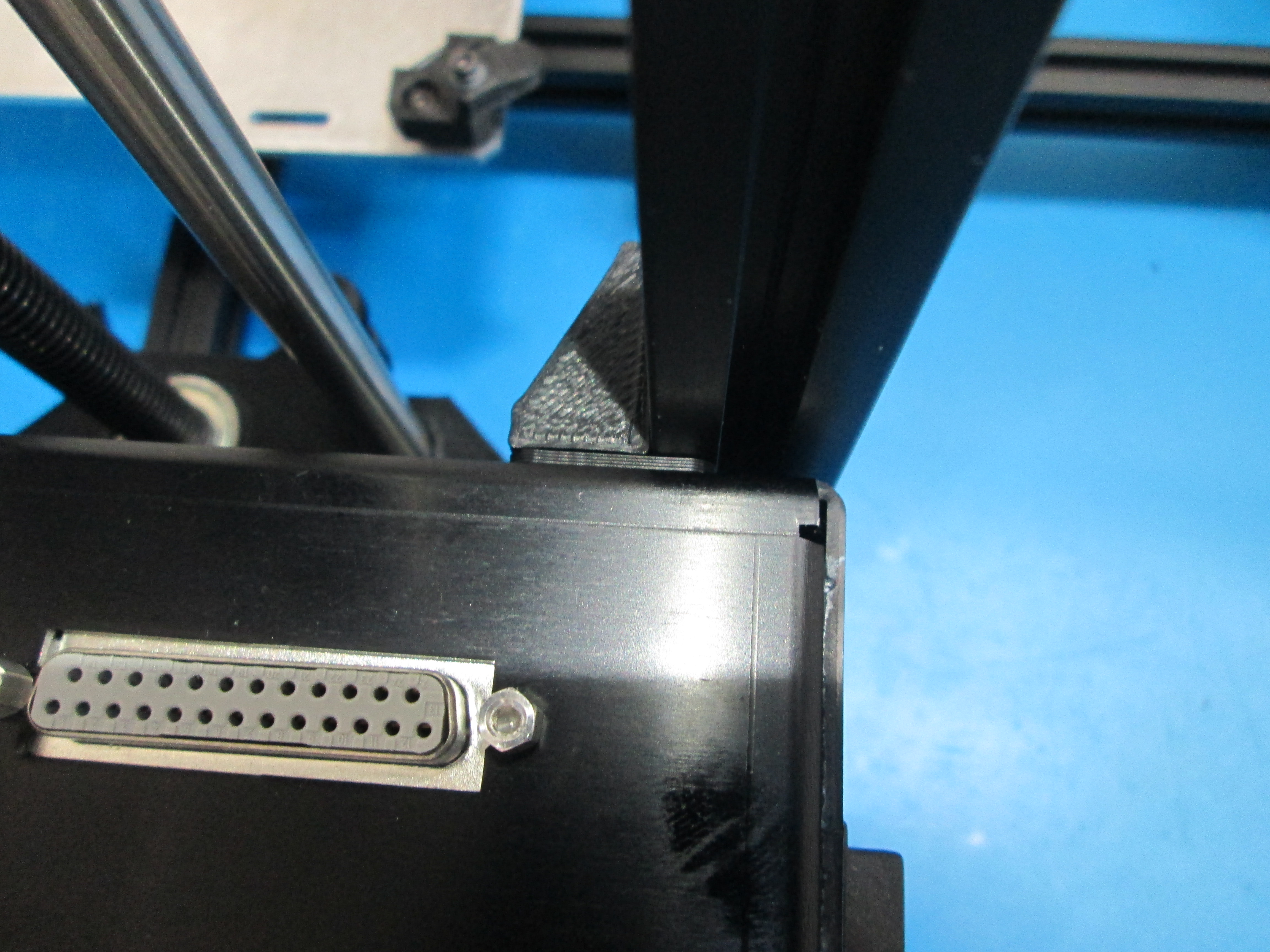
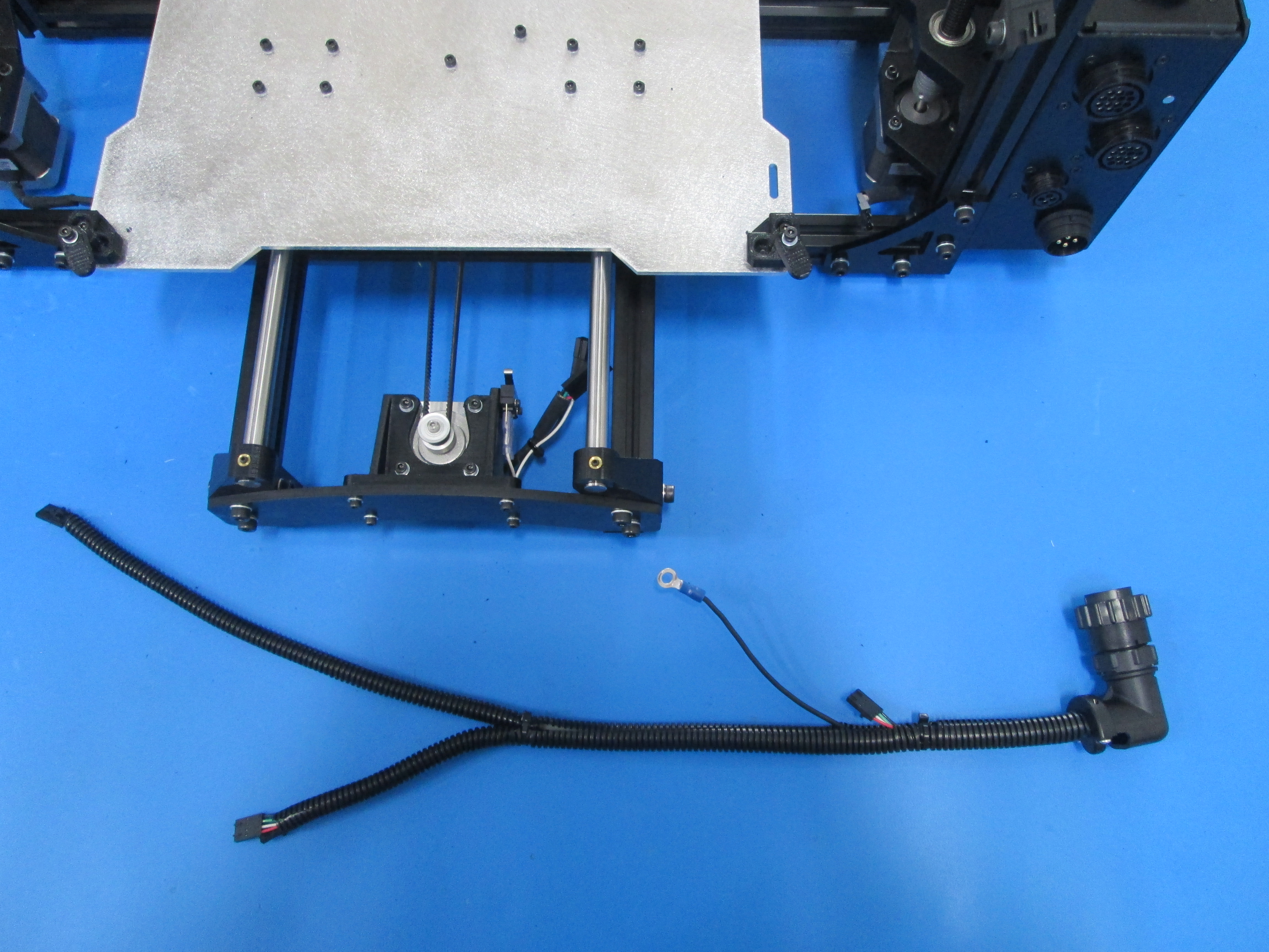
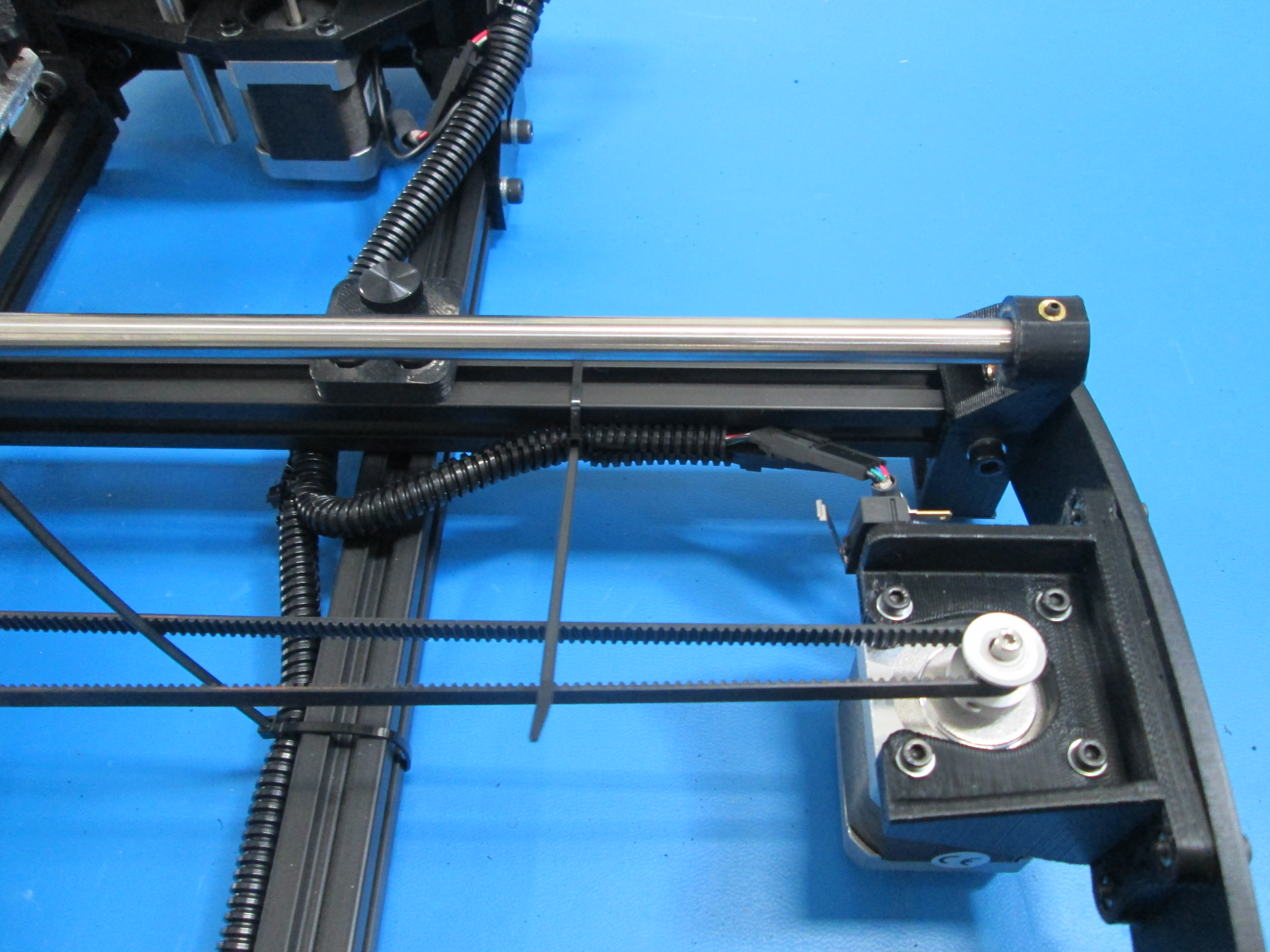
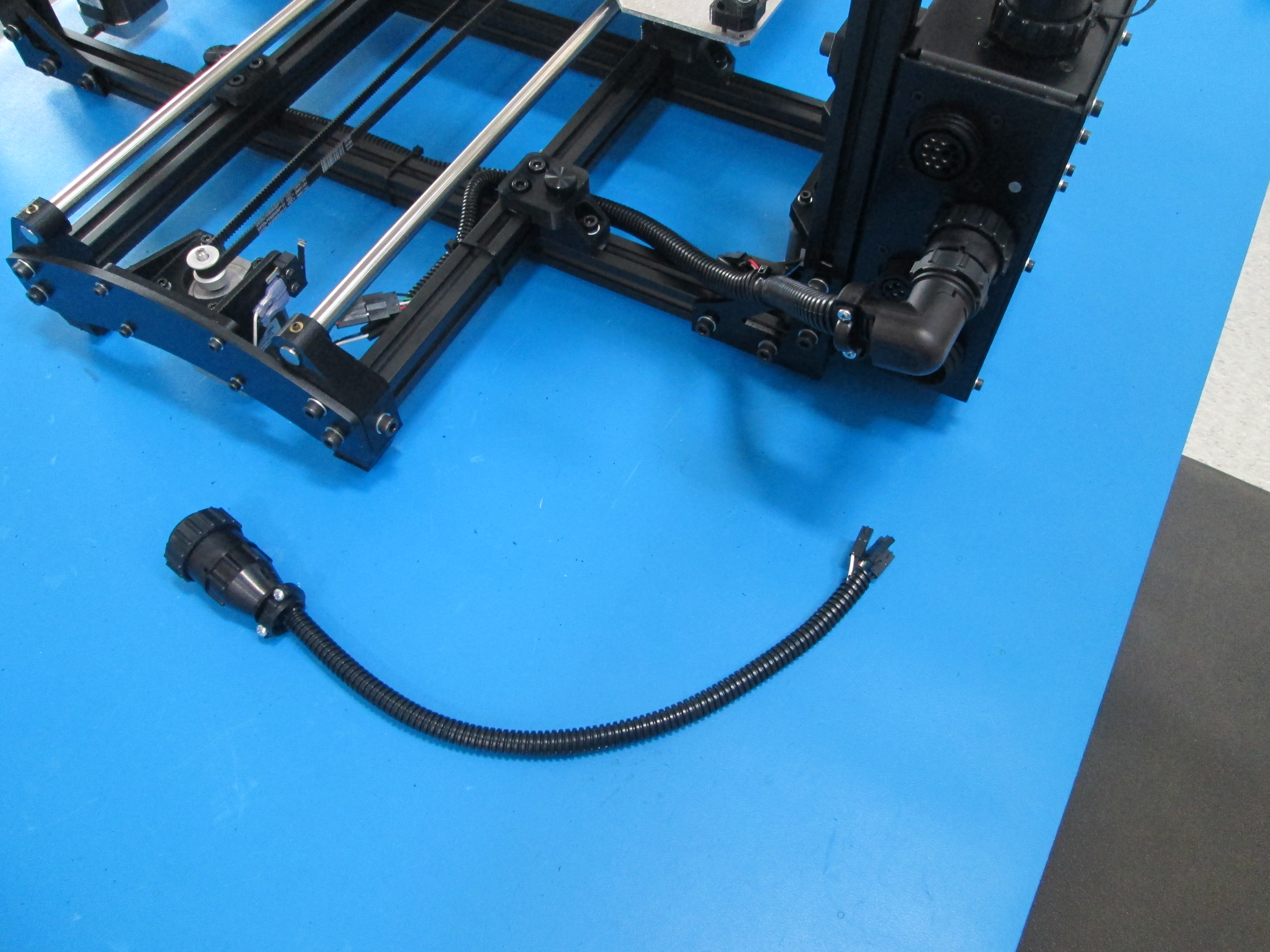
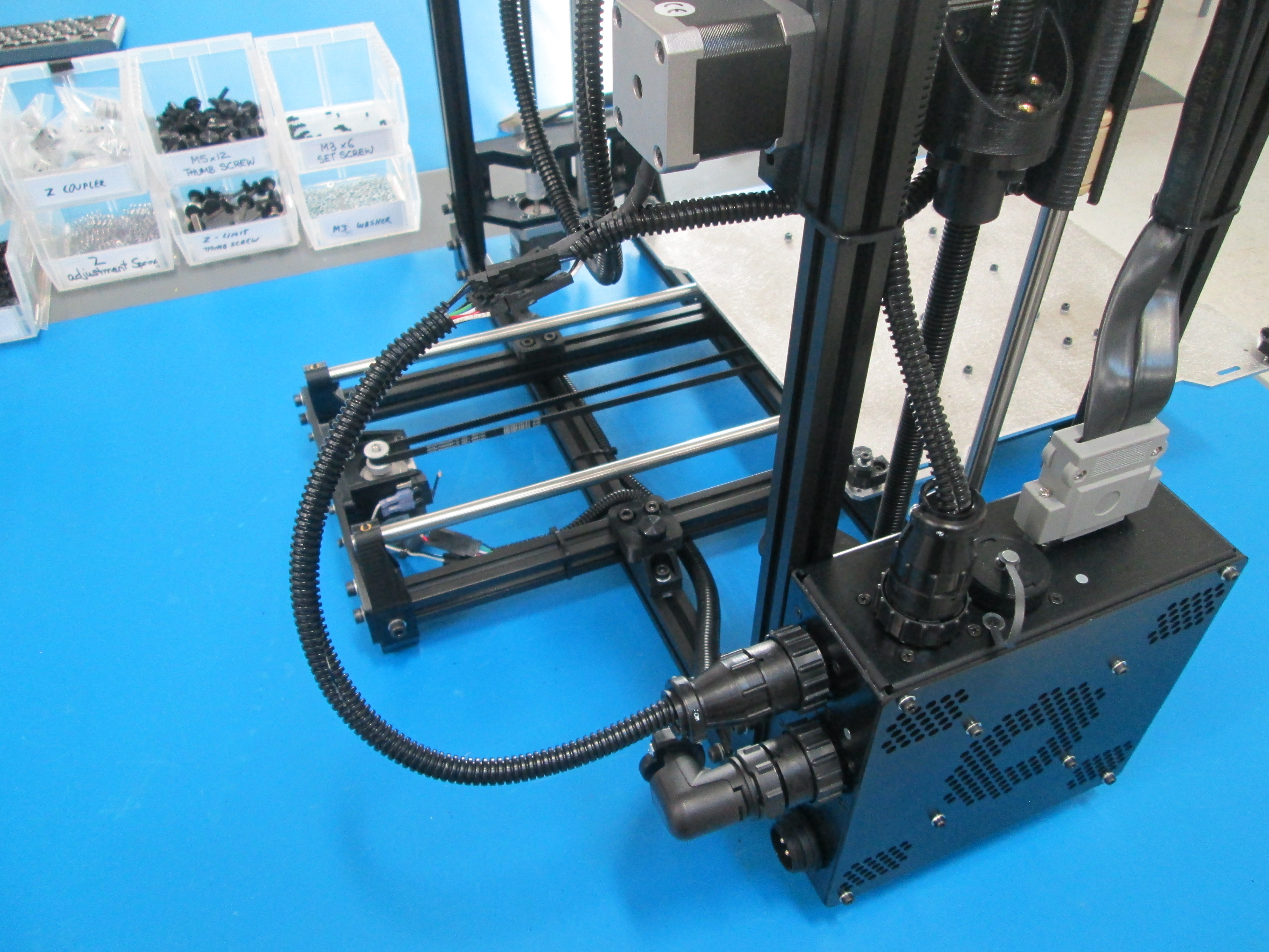
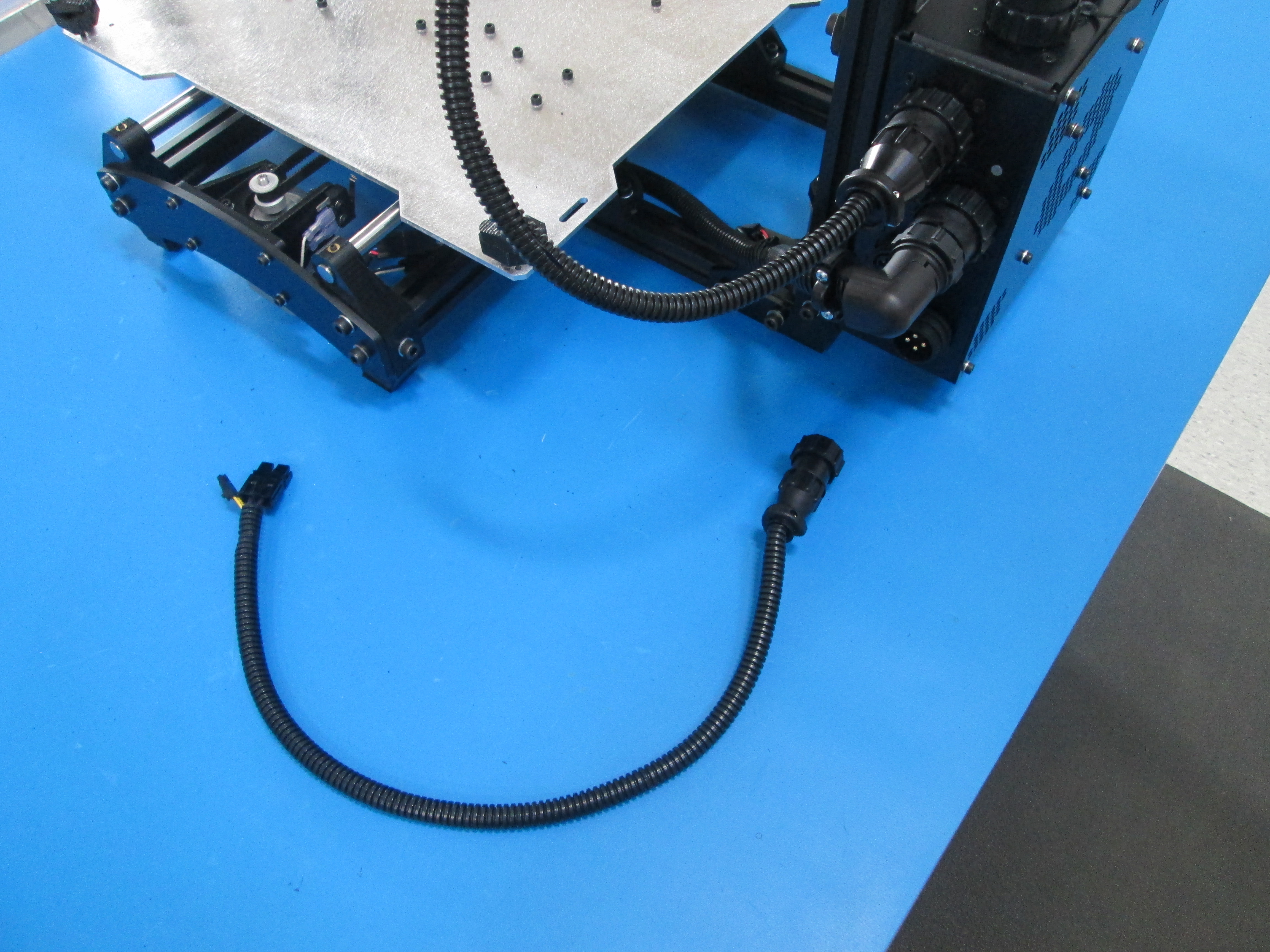
Connect the YZ harness to the 2nd connector down on the back of the control box as shown.
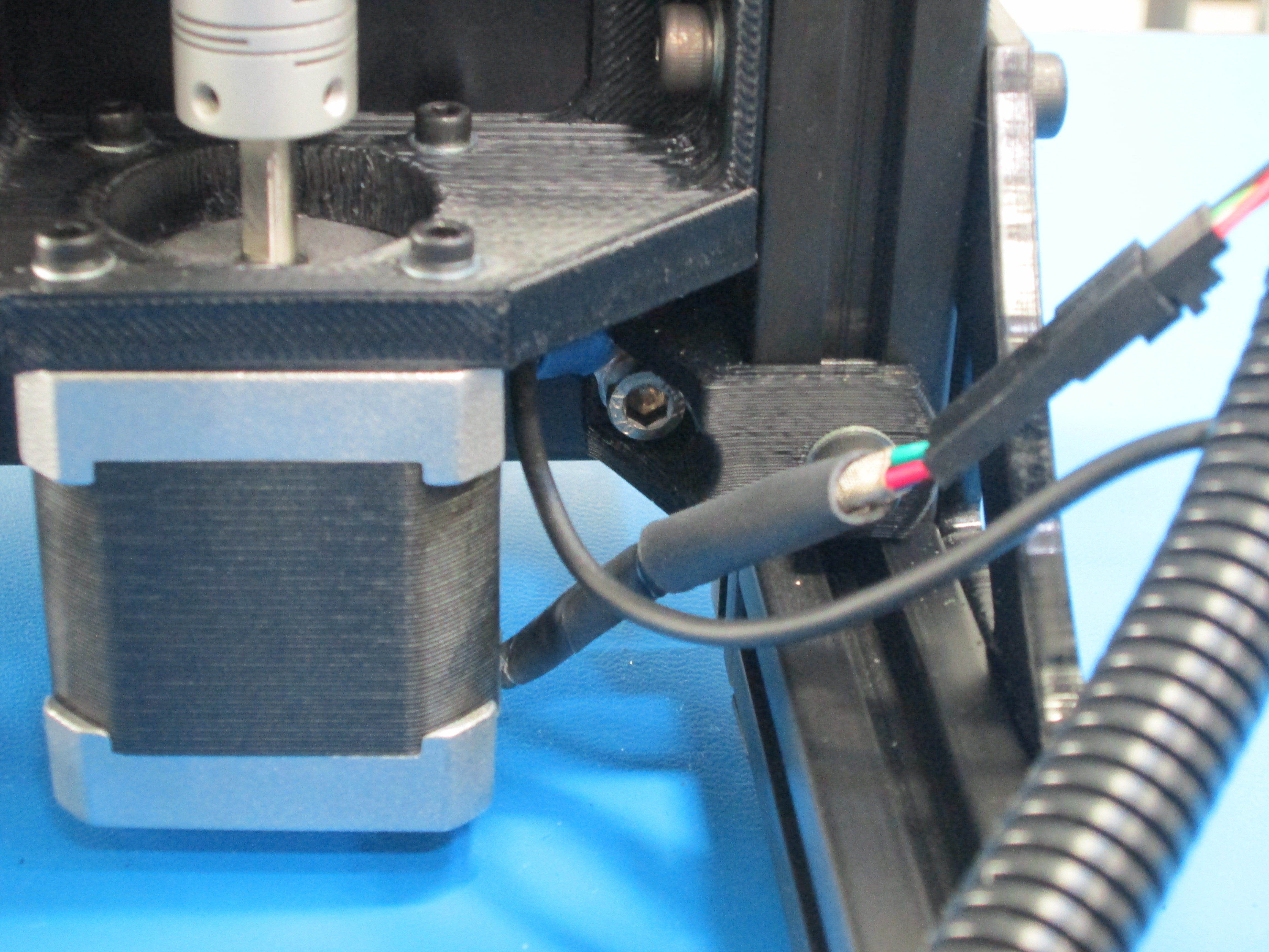
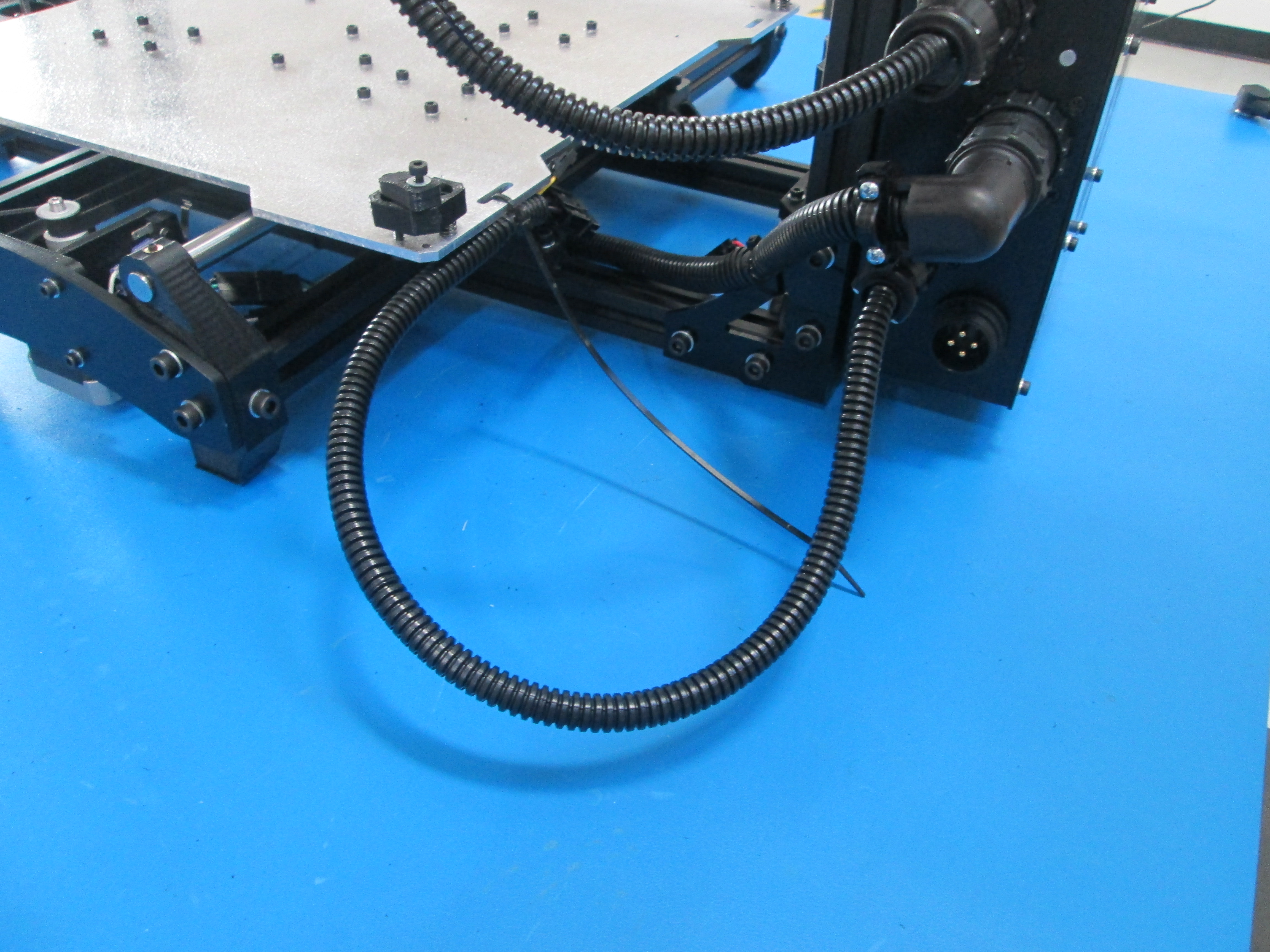
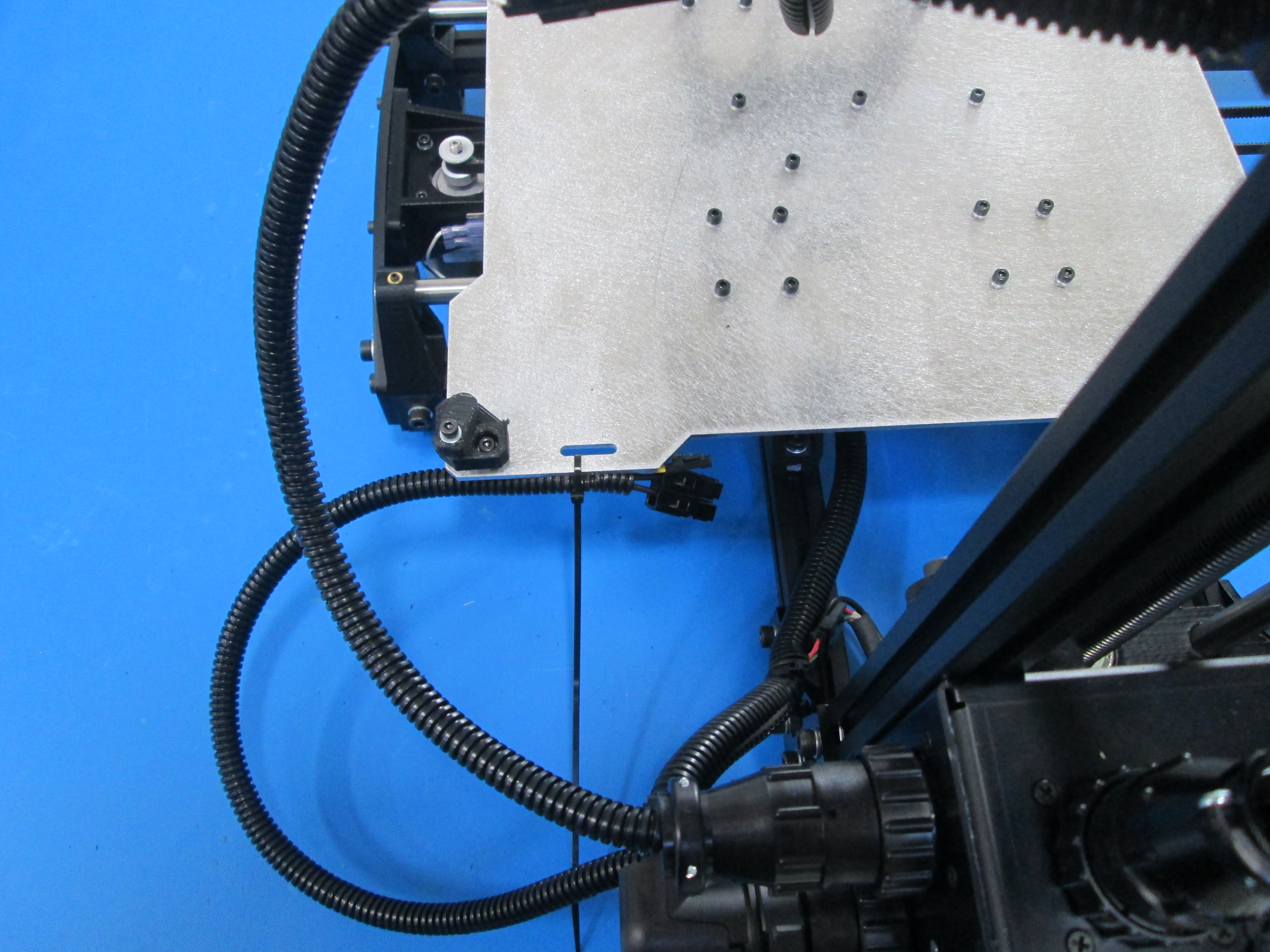
Route the YZ harness around the back of the frame and under the Y axis and connect the left Z motor as shown.
Route the Y motor extension over the frame and connect the Y motor and limit switch wire as shown.
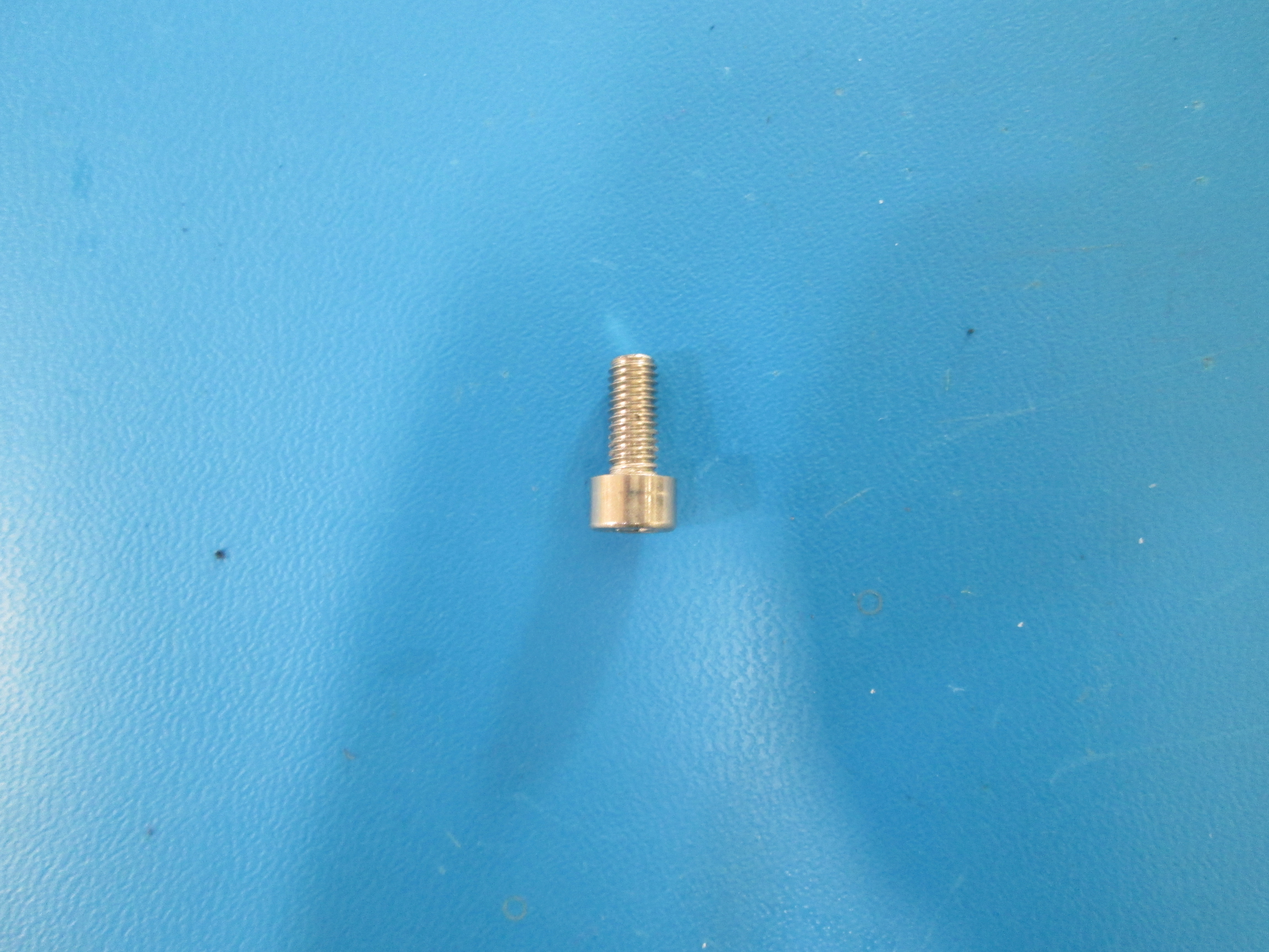
Connect the ground lug to the bottom right electronics case mount using a M5x12 Stainless SHCS, with no washer as shown.
Zip tie in the 4 locations as shown.
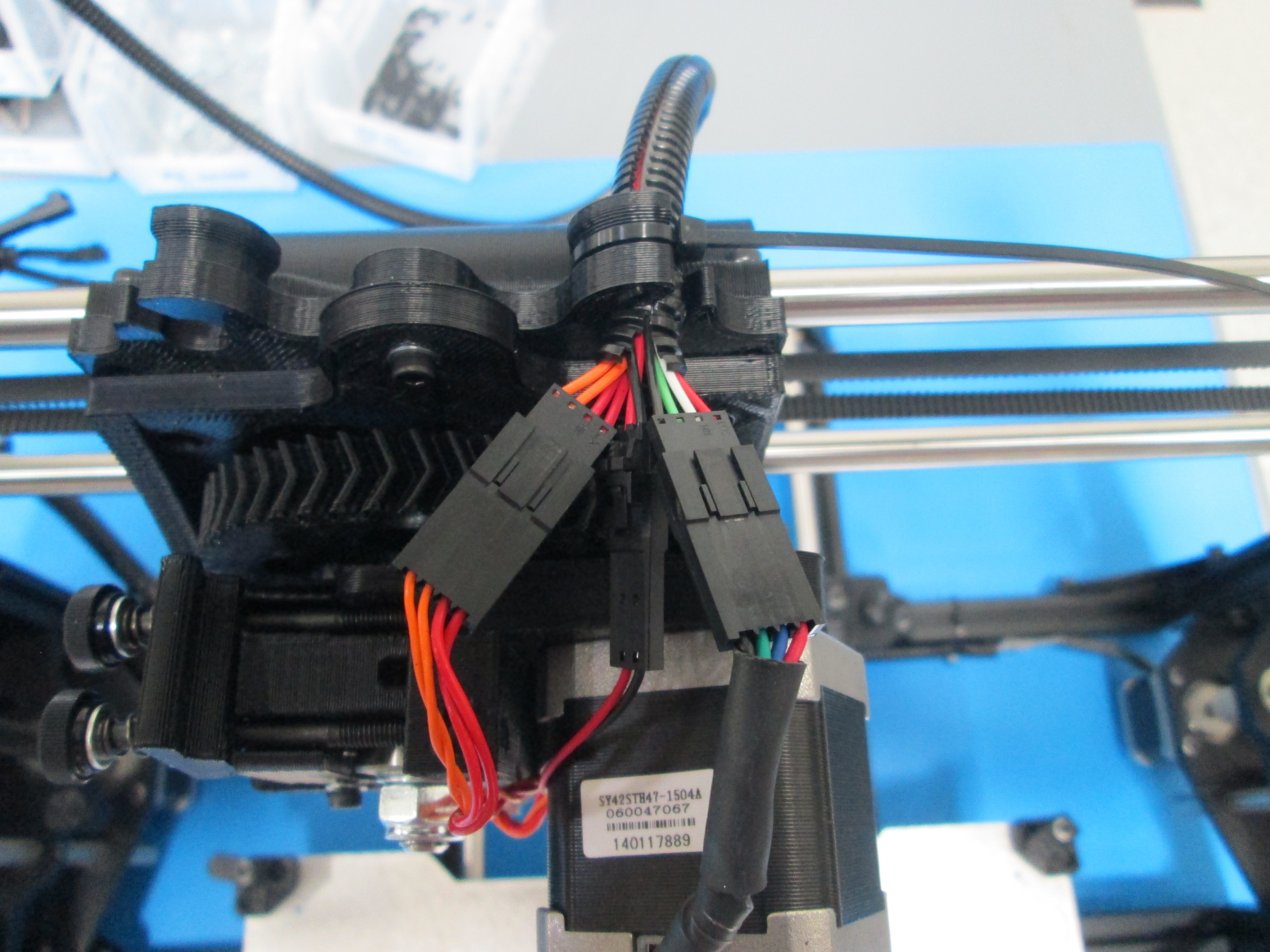
Connect the extruder harness connector to the Extruder #1 connector on the control box as shown.
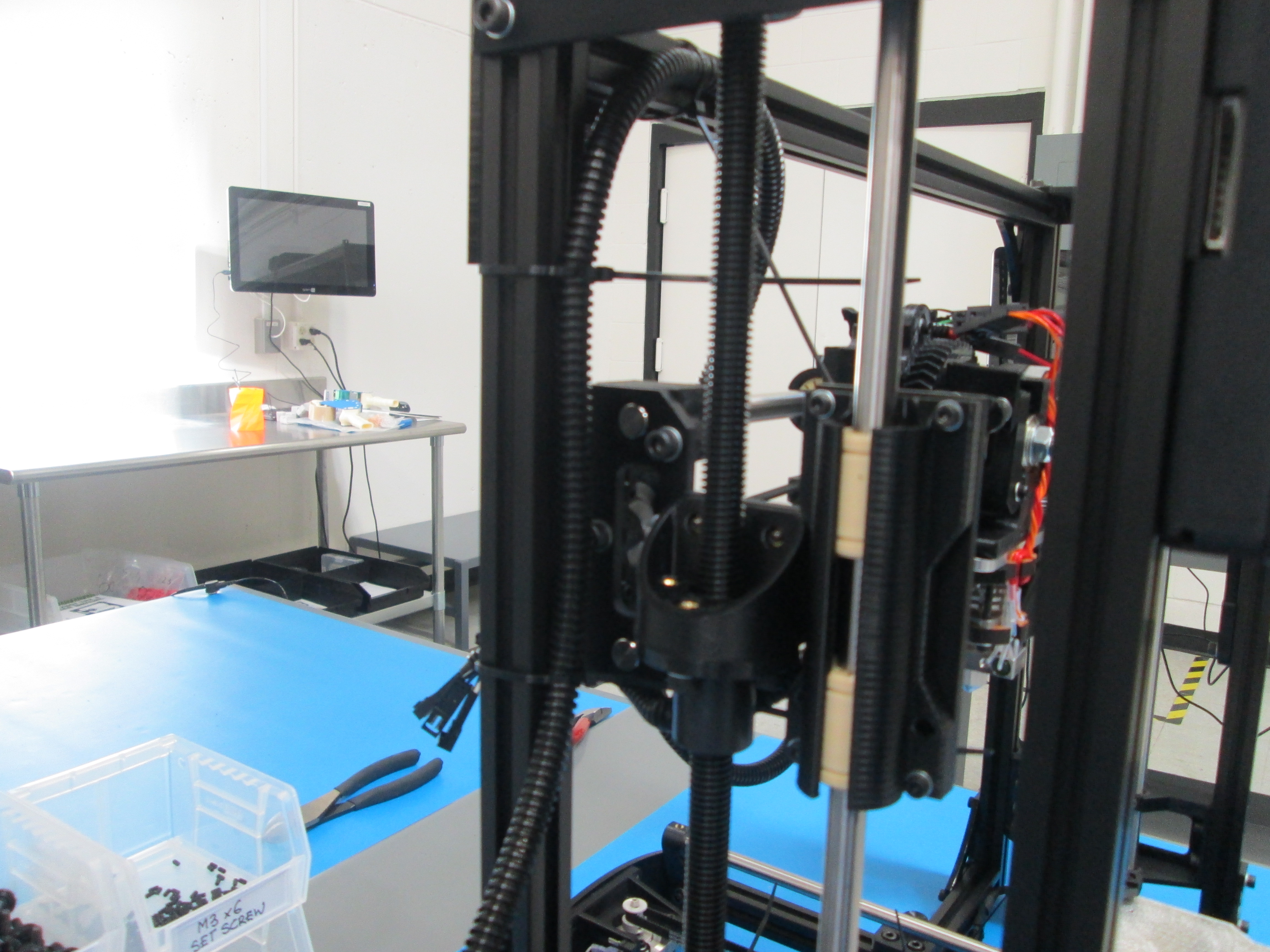
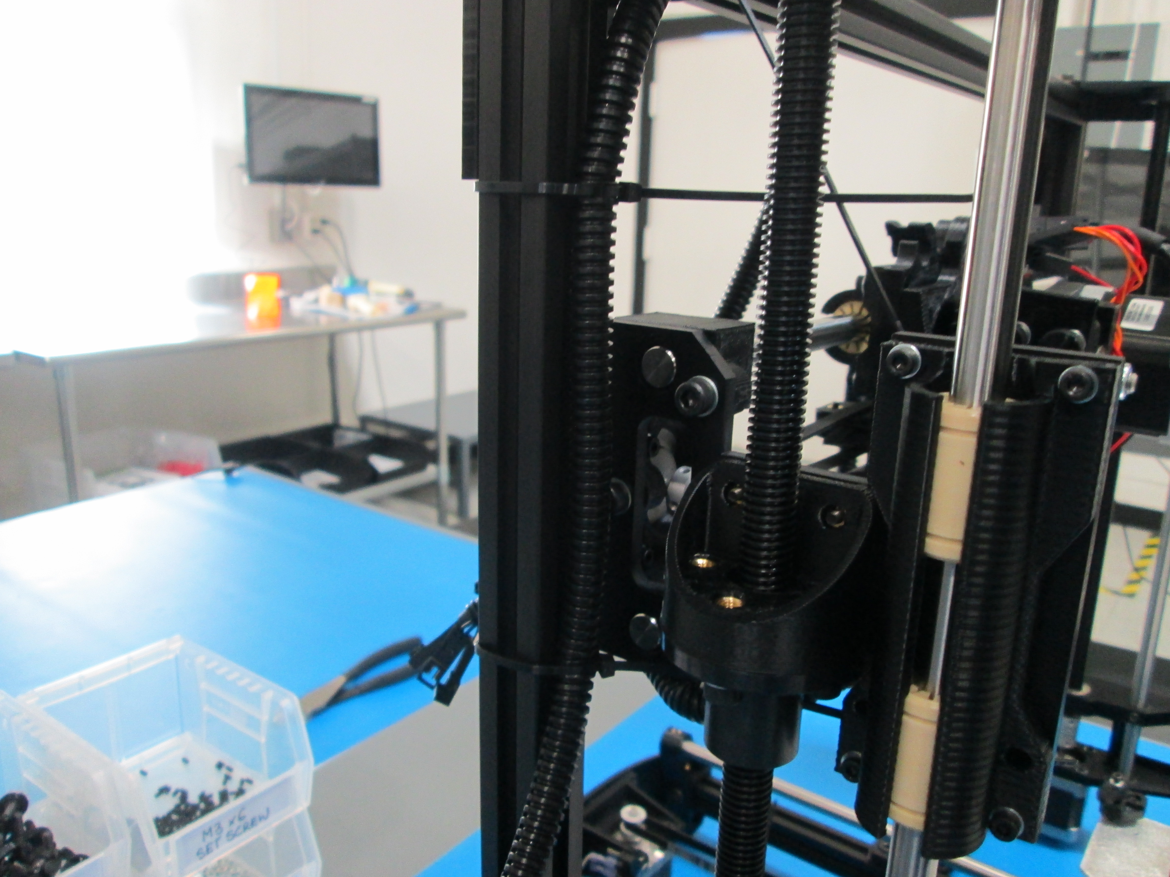
Route harness through the inside of the frame as shown.
Connect harness to print head and extruder fan wires.
Zip tie in the 4 locations as shown.
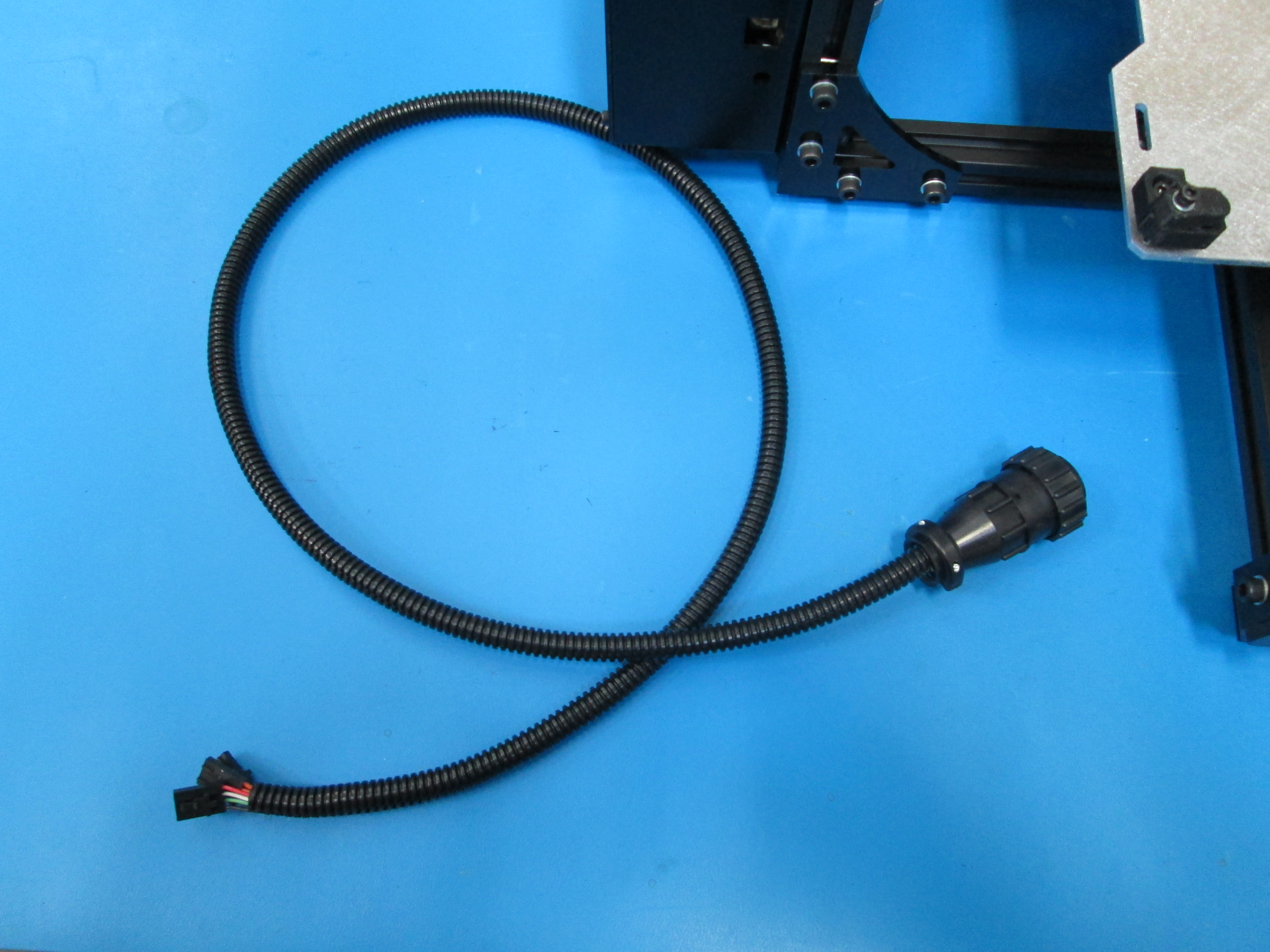
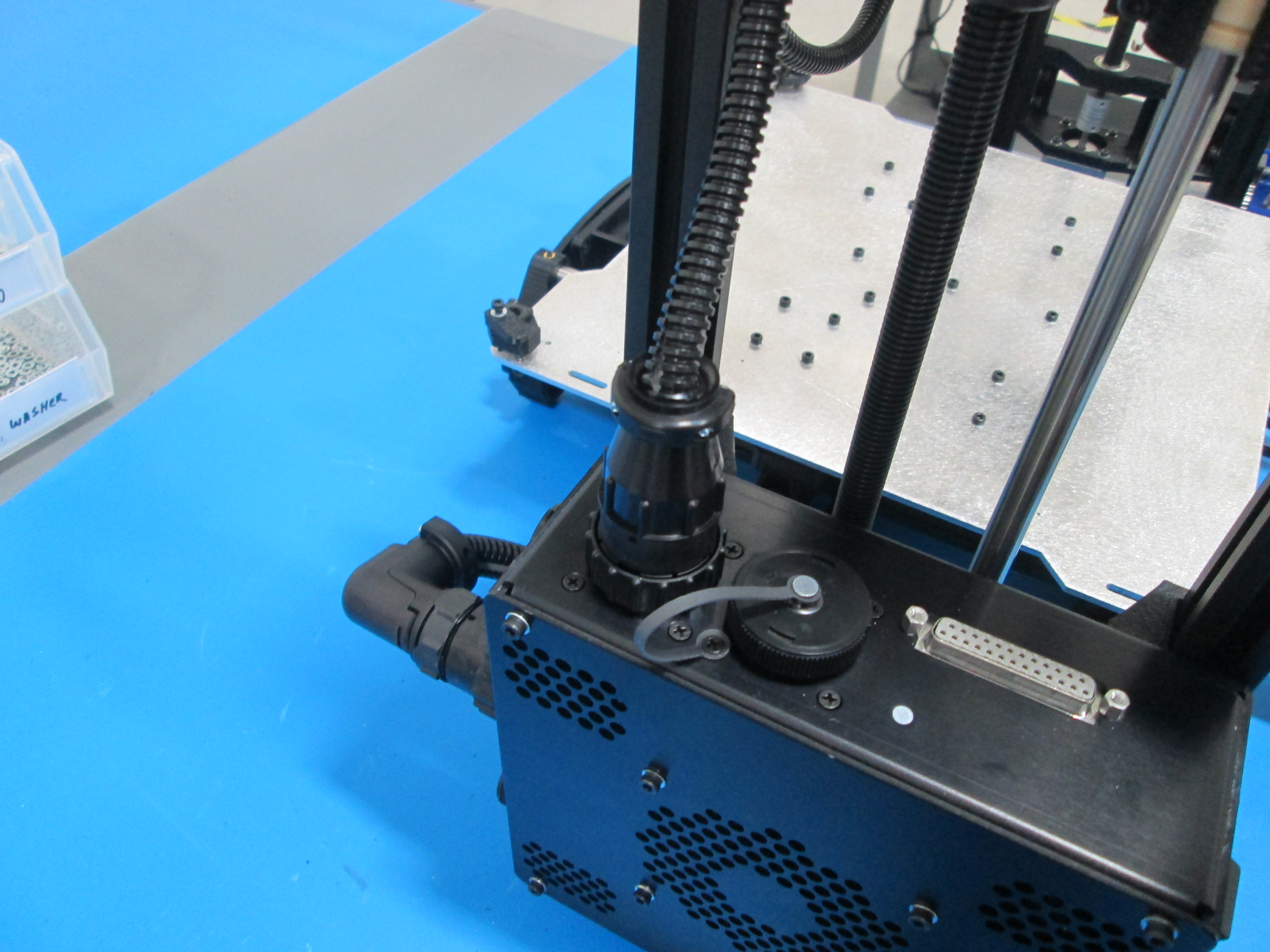
Connect the XZ harness to the top connector on the back of the control box as shown.
Connect the other end of the XZ harness into the X motor and matching limit switch wires as shown.
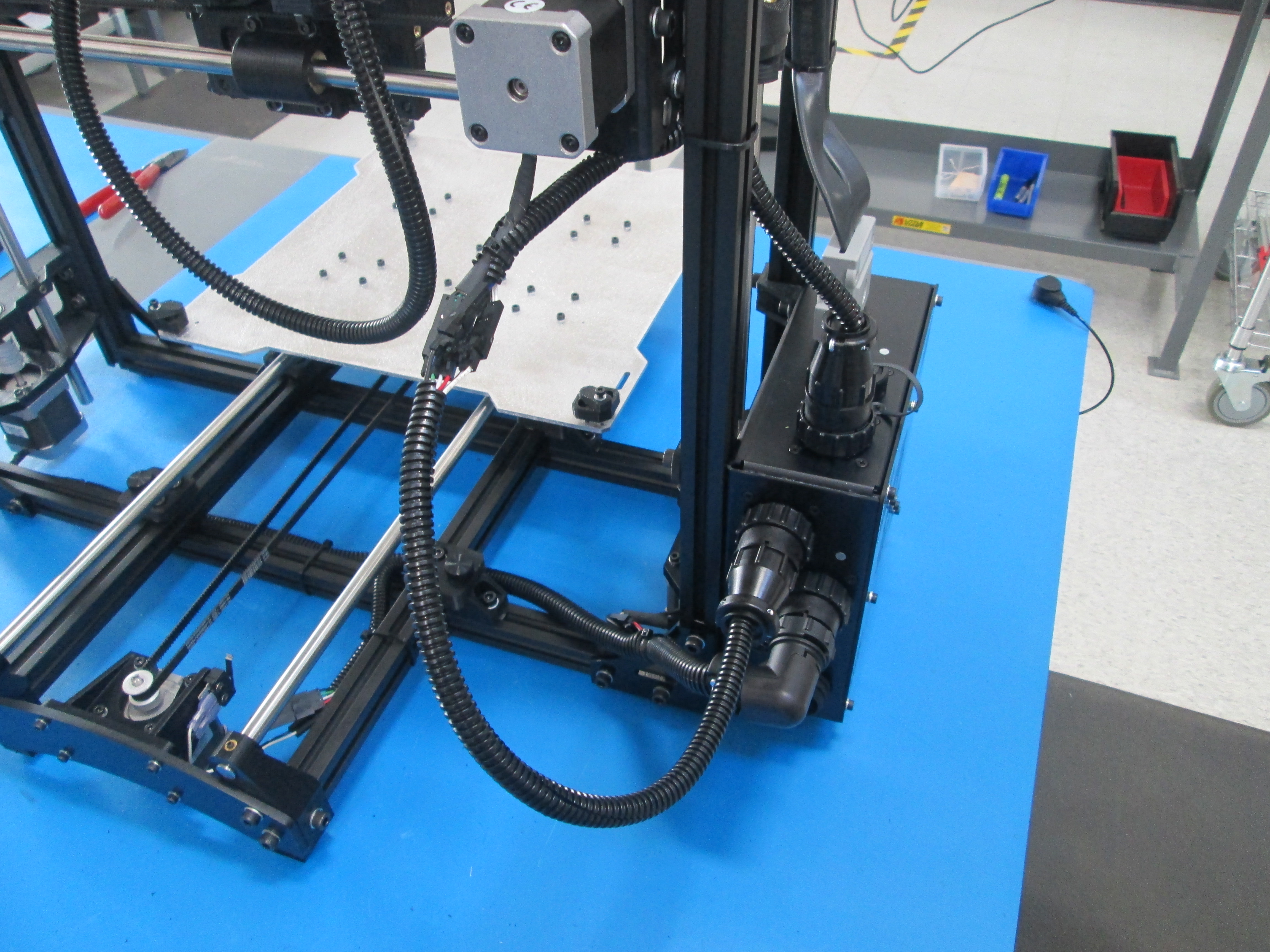
Connect the heat bed harness to the 3rd connector down on the back of the control box as shown.
Route the heat bed harness around the back of the frame and zip tie the other end to the Y axis plate as shown.
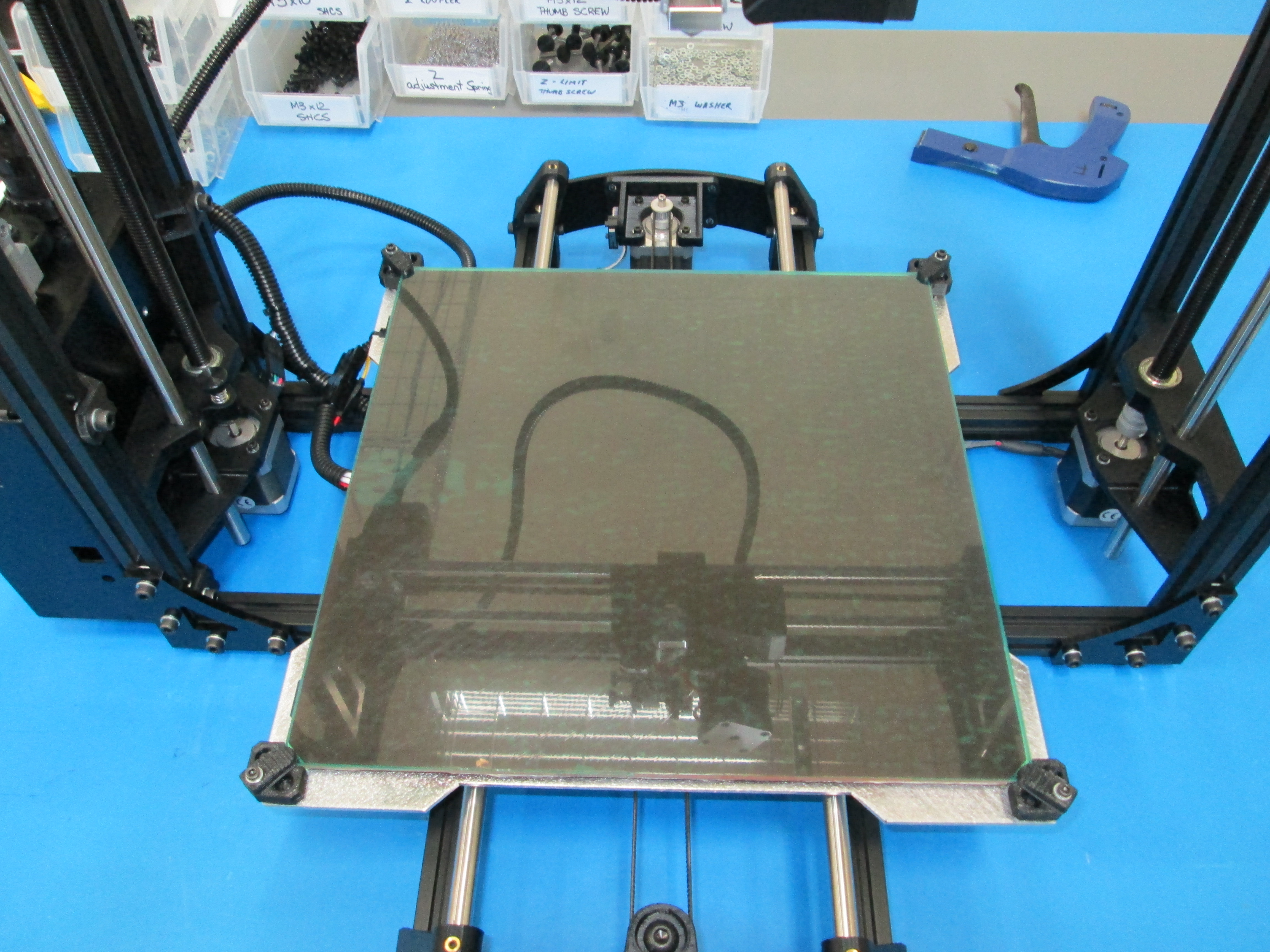
Carefully place the heat bed in the 4 bed corners with the heat bed wire oriented to the left as shown.
Place the 4 bed fingers onto the bed and tighten carefully.
On the front left hand corner of the bed, rotate the bed finger clip clockwise, so that the glass bed finger clip is half on/half off the glass. That should allow for the nozzle to sit in the corner, yet still have clearance.
Connect the heat bed to the heat bed harness.