Open HardwareAssembly Instructions
Guides for installation and assembly of the LulzBot line of products made by FAME 3D LLC.
Guides for installation and assembly of the LulzBot line of products made by FAME 3D LLC.
The Schleuniger UniStrip 2300 is a semi-automatic stripping machine capable of fast, reliable stripping of wire ends.
This guide will assist you in effective use of the UniStrip 2300.
Refer to the diagram(s) to familiarize yourself with the machine and user interface;
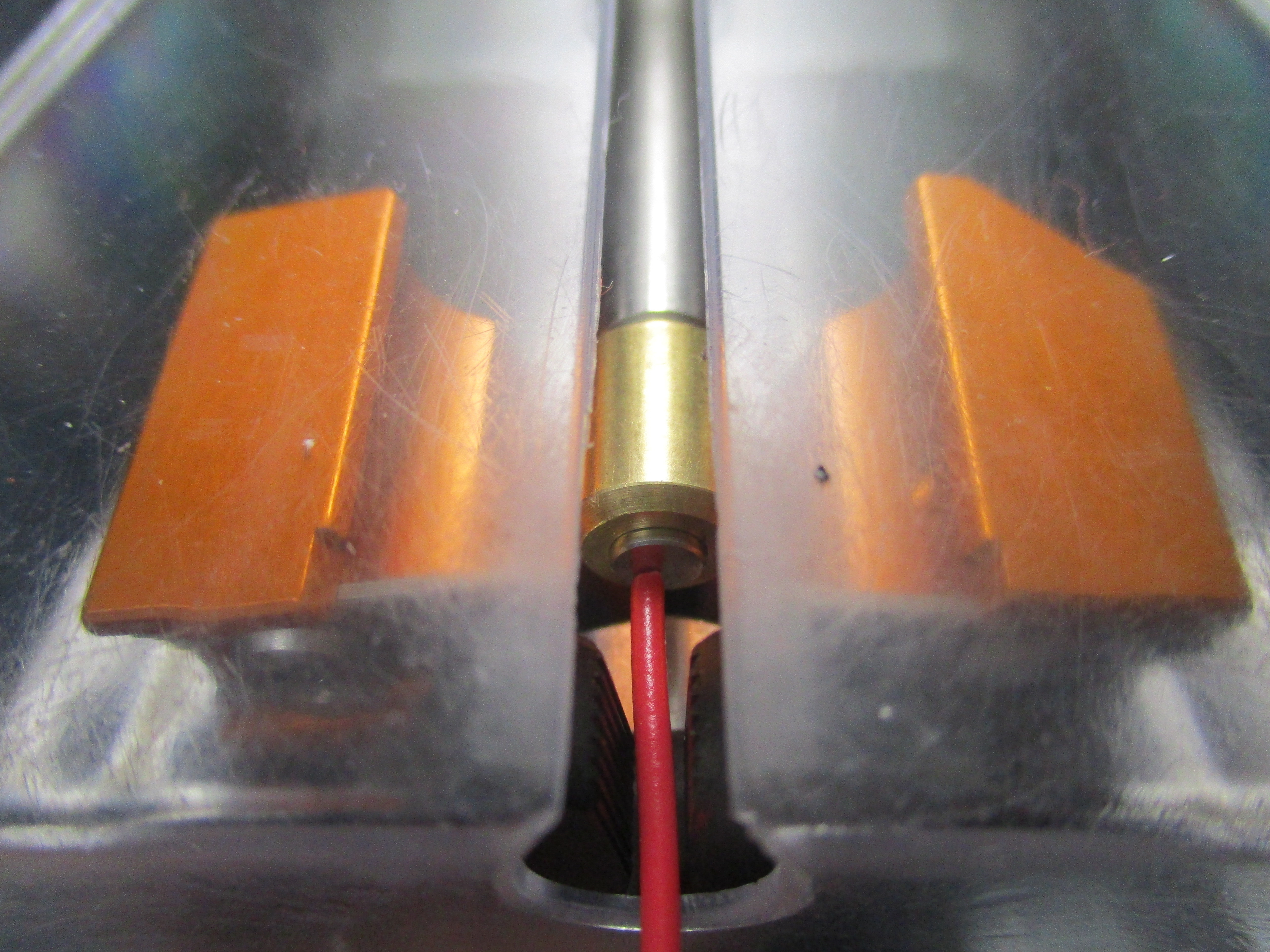
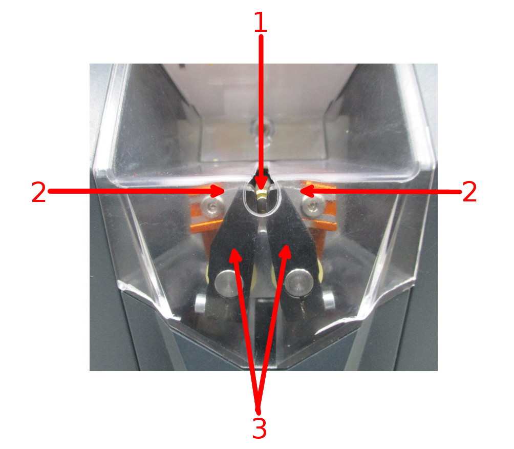
Overview of Components:
1) Trigger Button – once the machine is programmed, the user will use the end of the wire to be stripped to trigger the
button and the wire will be stripped
2) Blades – V-shaped blades which perform the cut and pull-off operations of the machine
3) Clamping jaws – hold the wire in place while being stripped
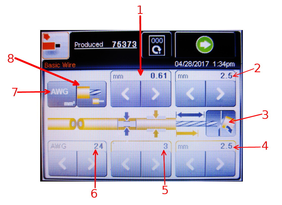
Overview of Basic Wire Mode:
1) Conductor Diameter – diameter of inner conductor(s) of the wire
2) Strip length – desired length of strip
3) Discard Toggle – Toggle whether to strip the wire completely
4) Pull-off length – length to pull off
5) Clamping force – amount of force applied between the clamping jaws
6) Conductor cross section (AWG) – gauge of wire being stripped
7) Wire Type – Toggles between mm^2 and AWG
8) Conductor Type – Toggles between stranded and solid core conductors
Before beginning, specify the gauge (AWG) of wire to be stripped and the strip length. Refer to the diagram above.
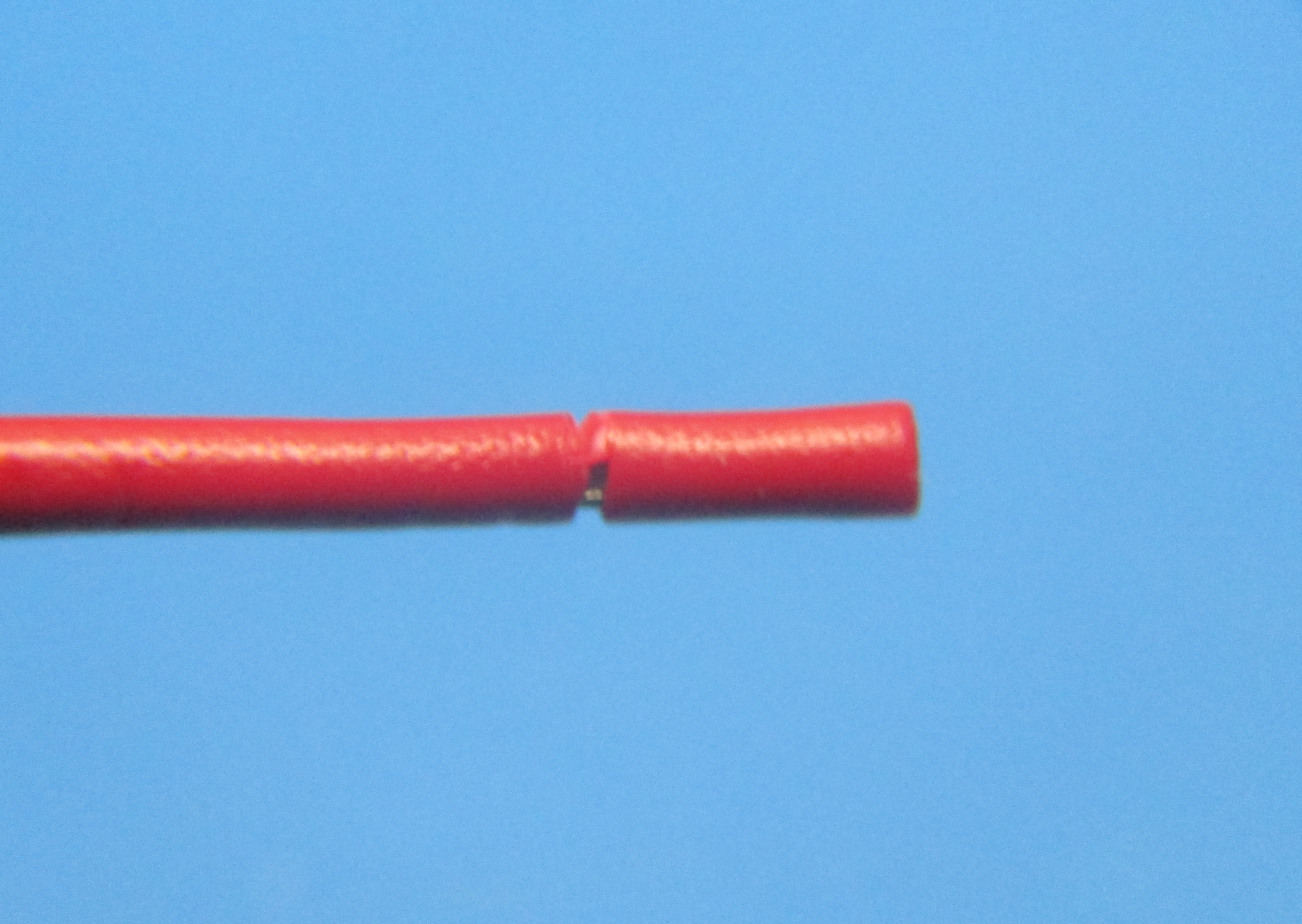
Typically when stripping with the UniStrip, we remove the strip slugs completely, therefore the pull off length should always be the same as the strip length.
If the pull off length is less than the strip length the machine will not remove the slug completely and triggering the Re-cut/Discard Toggle (3) would result in the wire being cut again at the specified pull off length. The result would be a strip matching the specified pull off length, and a wire that is shorter by the difference between strip and pull off length.
With pull off length set to match strip length, the Re-cut/Discard Toggle will show the Discard symbol. Disengaging this toggle with matching strip and pull off lengths has no effect.
Conductor diameter (1) is automatically adjusted while setting wire gauge but as individual raw material varies, pay close attention to whether any conductors are being damaged during the stripping process, and increase this value if necessary.
If at any point the machine fails to perform as directed, request authorized personnel calibrate the machine as necessary, do not attempt to recalibrate the machine.
Begin stripping wire by passing the end of the wire to be stripped through the circular opening on the front of of the machine, using the end of the wire to touch the trigger button.
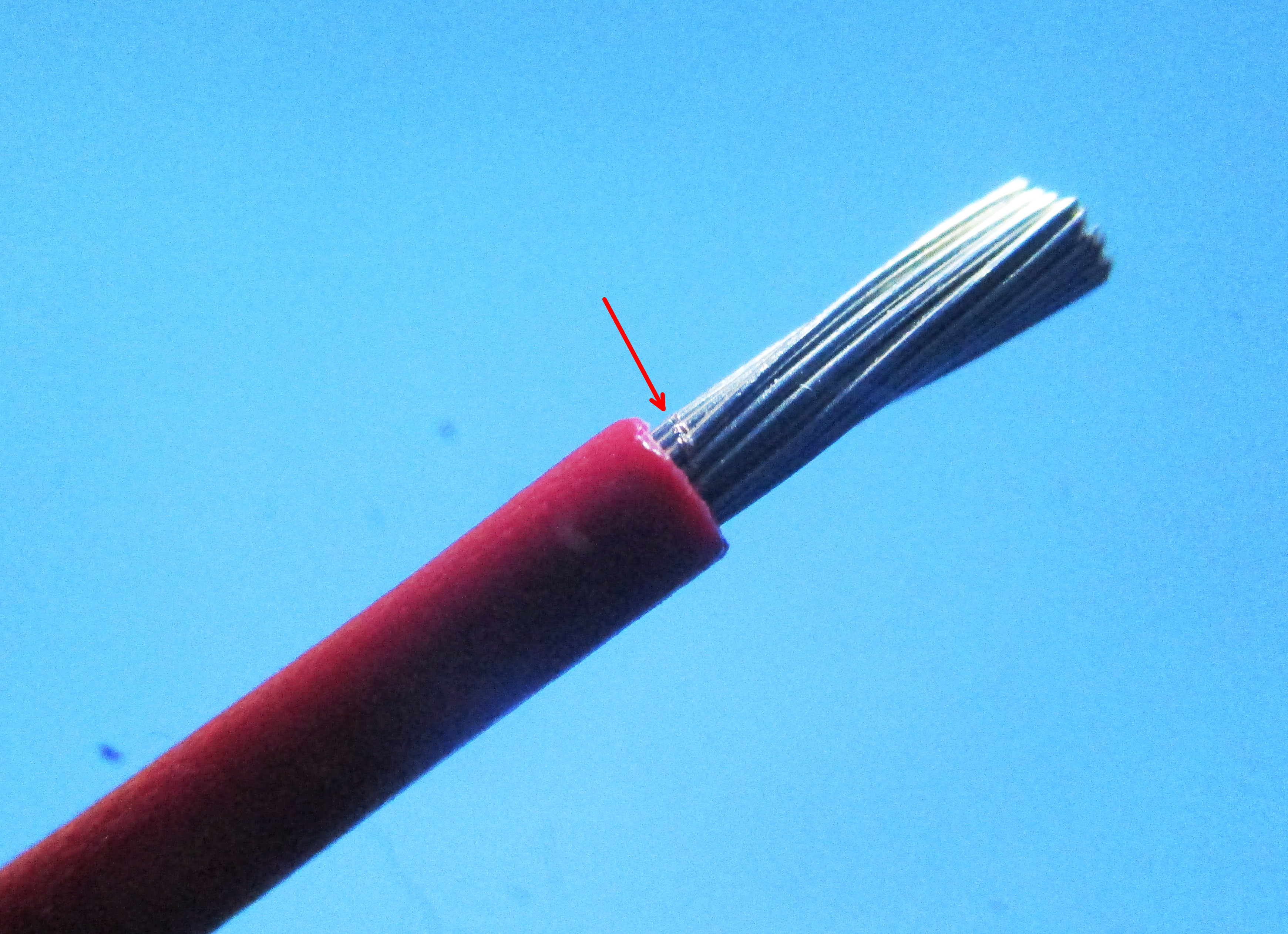
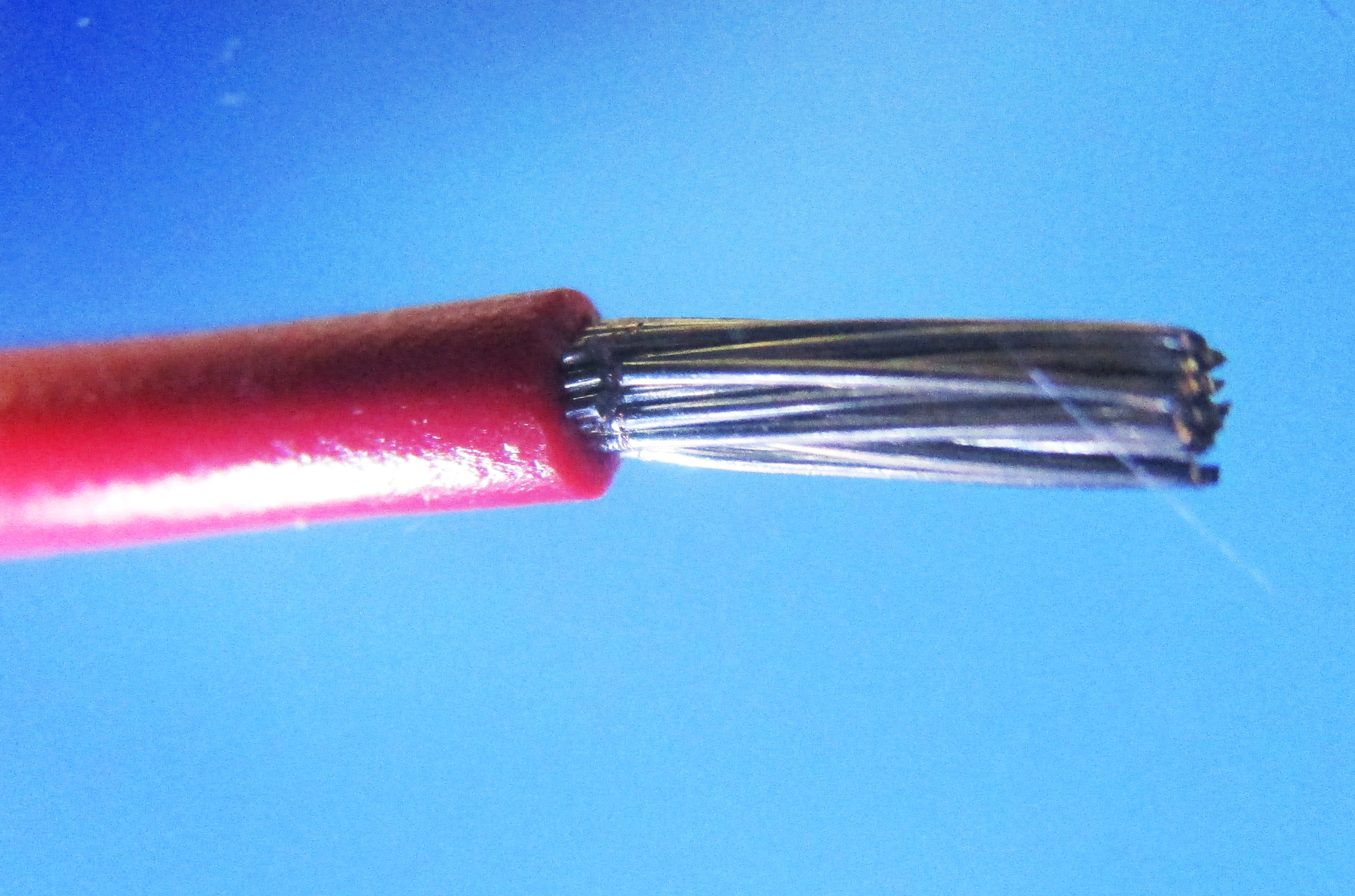
Visually verify that the desired strip length has been achieved and no conductors are damaged or cut.
Continue to feed individual wire ends into the machine, lightly touching the trigger button with each, until all wires are stripped as desired.
Wire slugs tend to gather around the blades and trigger of the machine and can sometimes interfere with operation.
Whenever a build-up occurs, use a short burst of compressed air towards the trigger button.
DO NOT insert the nozzle of the compressed air into the machine’s safety guard for any reason. Compressed air is enough to trigger the button and cause the blades to move, this could result in damage to the blades as well as the compressed air nozzle.