Open HardwareAssembly Instructions
Guides for installation and assembly of the LulzBot line of products made by FAME 3D LLC.
Guides for installation and assembly of the LulzBot line of products made by FAME 3D LLC.
5x- [HD-BT0073] M5x10 BHCS, Black-Oxide
3x- [HD-BT0157] M3x8 SHCS, Black-Oxide
1x- [HD-BT0185] M3x16 SHCS, Black-Oxide
1x- [HD-BT0222] Blue-Dyed Zinc-Plated Alloy Steel Socket Head Screw M3x50
2x- [HD-BT0223] Blue-Dyed Zinc-Plated Alloy Steel Socket Head Screw M3x16
1x- [HD-BT0225] M5x10 BHCS, Stainless Steel
4x- [HD-MS0554] Workhorse, M5 x 0.8 Knob Thumb Screw Drive, Stainless Steel
8x- [HD-MS0058] Wire Tie, 8" Black, pk 1000
2x- [HD-RD0066] 12mm Smooth Rod, Stainless Steel, 540mm EWMR-12-540x
1x- [HD-WA0007] M5 Washer, Steel, Zinc Plated
4x- [HD-WA0038] M3 Washer, Black-Oxide
5x- [HD-WA0040] M5 Washer, Black-Oxide
4x- [PP-GP0448] Thumbscrew Leash, LulzBot Green, Flexible
1x- [PP-GP0447] Interconnect Strain Relief, Black
1x- [PP-GP0405] Z Endstop Cable Cover
5x- [PP-GP0390] Cable Clip
1x- [PP-GP0380] X-Belt Clamp with Insert
1x- [AS-PR0166] X Carriage Assembly
1x- [AS-PR0165] TAZ Workhorse, Final Frame Assembly
1x- [AS-PR0163] Y-Axis Assembly, Workhorse
1x- [AS-TH0076] Workhorse Toolhead
1x- [AS-PR0162] Control Box Assembly, Workhorse

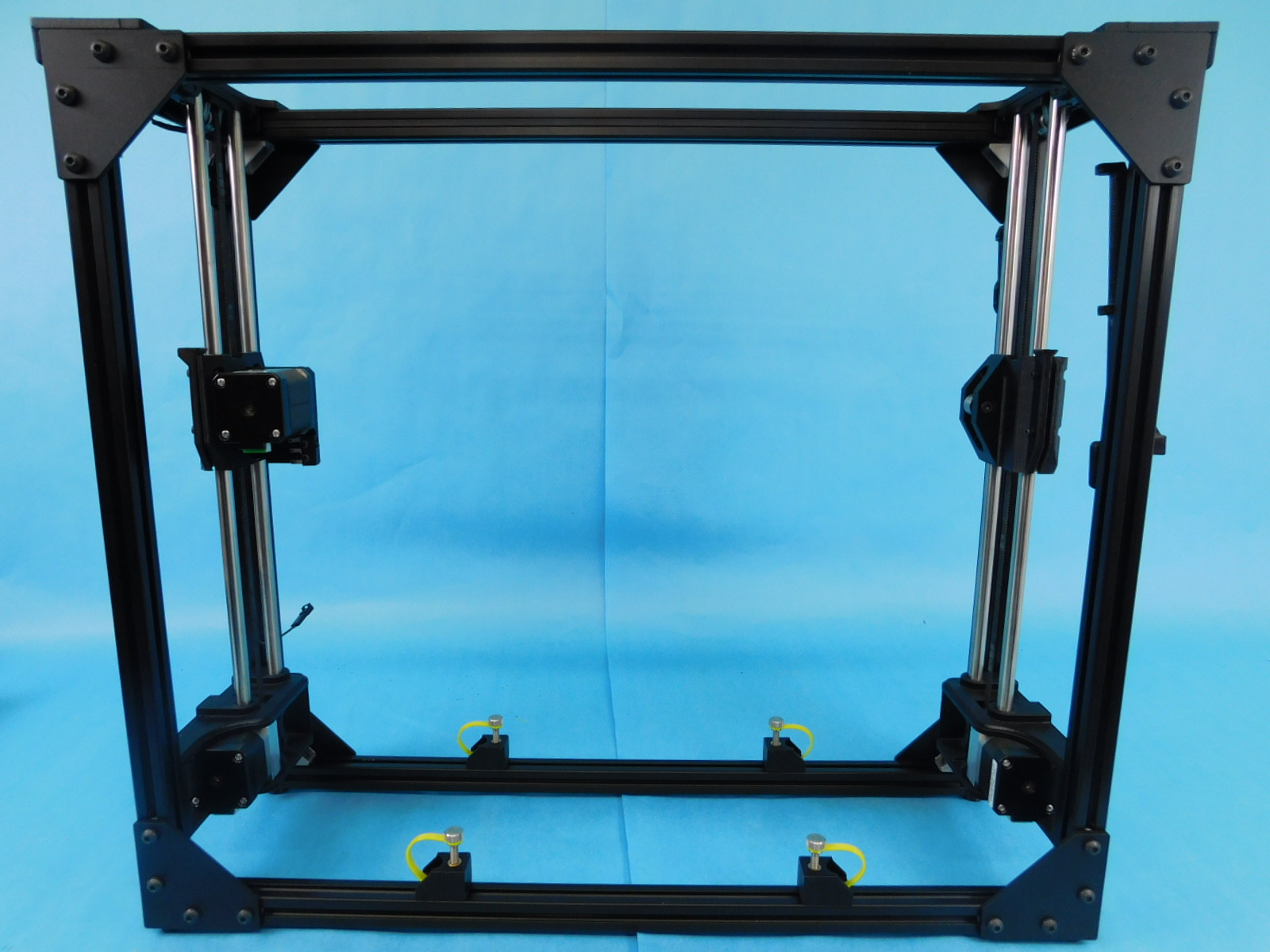


Obtain a completed Frame Assembly [AS-PR0165]
Place the completed frame on the granite block and verify that it sits flat and and doesn’t teeter, like a chair with one short leg.
Line up the square along both ends, perpendicular to the length of the frame, as pictured.
Examine the relationship between frame and square. If at any point the gap meets or exceeds 2mm, the frame must be rejected for re-squaring.
If the frame has passed inspection, place it on your workbench with the back of the machine facing you.


Wipe down the smooth rods to ensure they are free from any contaminants.
Move both sides of the Z-Axis (X-Ends) to the top of travel by grasping the printed part and pushing it upwards.
Obtain one 12mm Smooth Rod [HD-RD0066] and slide it through the lower 12mm hole of the X Idler End from the outside of the frame, stopping about half way.
Place the double bearing side of the X Carriage Assembly [AS-PR0166] onto the smooth rod end inside the frame, oriented as pictured.
Continue sliding the 12mm Smooth Rod [HD-RD0066] into the lower 12mm hole of the X Motor End until the end of the rod is flush with the outside of the X-Idler End (right side of frame).
Torque both lower smooth rod set screws (located on the underside of the X-Ends) to 3in*lbs.


Push the axis to the middle of travel (mid-frame) by applying even downward force on the X-Ends.
Rotate the frame so the back is facing you.
Orient the X Carriage Assembly [AS-PR0166] upright as pictured.
Straighten the X Axis drive belt attached to the X Carriage Assembly and route the end through the X-Idler End, beginning above the bearings with the teeth of the belt facing down.
Ensure there are no twists in the belt
Continue routing the X Axis drive belt back through the X-Carriage Assembly below the tensioner and behind the Interface Board Mount.
Route the drive belt around the X Motor pulley, beginning from below the pulley with teeth facing up.
Route the belt through the clamp feature of the X-Carriage as pictured.
Place one X Belt Clamp w/ Insert [PP-GP0380] into the feature as pictured and thread one M3x16 SHCS [HD-BT0185] with washer [HD-WA0038] into the insert from above.
Using a pair of pliers, remove slack from the drive belt by pulling on the end.
Do not tension the belt at this point, only remove the slack
Torque the X-Belt Clamp fastener to 5in*lbs


Wipe down the smooth rods to ensure they are free from any contaminants.
Push the axis to the bottom of travel so that both ends rest upon the Z-Lowers.
Obtain one 12mm Smooth Rod [HD-RD0066] and slide it through the upper 12mm hole in the X-Idler End from the outside of the frame.
Continue through the upper bearing of the X-Carriage and into the upper 12mm hole of the X-Motor End until the end of the smooth rod is flush with the outside of the X-Idler End.
Torque both upper smooth rod set screws (located on the top side of the X-Ends) to 3in*lbs.


Raise the axis by hand back to the mid-travel position and rotate so the front of the unit is facing you.
The X-Axis bushings have compression features that allow the printed part to be tightened on the bushings to prevent unwanted motion.
Tighten the lower X-Axis compression bushing by tightening the flat head fastener on the bottom front of the carriage.
Tighten until you can no longer tilt the bushings on the rod, but ensure the bearing can still slide freely left to right.
Do the same for the upper X-Axis compression bushing by tightening the flat head fastener towards the top front of the carriage.
Now we will set the alignment between the upper/lower X Axis bushings.
Push the X-Double Bearing as far to the left as possible in relation to the X-Carriage during the following steps
Slide the X Carriage to the left end of travel against the X-Motor End and tighten the left button head fastener on the front of the carriage.
Torque to 5in*lbs
Slide the X Carriage to the right end of travel against the X-Idler End and tighten the right button head fastener on the front of the carriage.
Torque to 5in*lbs
Finally, tighten the bottom rear fastener on the X-Carriage to 5in\lbs


Looking at the rear of the X-Carriage Cover, apply counter-clockwise rotational force while tightening both fasteners to 5in*lbs
This will ensure that the Extruder Cap will sit flat in relation to the tool head.


Apply one Caution Hot Sticker [DC-LB0154] to the X-Carraige Cover as pictured.

Set the frame with the front facing you on its left side, towards the side or rear of your workbench.
Obtain one Control Box Assembly [AS-PR0162]
Place the Control Box Assembly cover side down on the workbench with the screen facing you.
Pick up the frame (still with front side facing you and the left side facing down) and place it on top of the Control Box Assembly.
The Z-Max wires will rest in the groove as pictured, ensure they are not pinched when installing the Control Box Assembly.
Place one Stainless M5x10 BHCS [HD-BT0225] with M5 Zinc-plated washer [HD-WA0007] into the metal case mount along the front extrusion to your left.
You will need to lift/hold the frame slightly to insert the fastener, you may also need to loosen the fastener attaching the bracket to the frame to align it with the threaded hole in the Control Box
Thread the fastener into the Control Box, do not tighten yet.
Secure the frame to the Control Box at the other 3 locations using three M5x10 BHCS [HD-BT0073] with washers [HD-WA0040].
Torque all 4 fasteners securing the mounts to the control box to 5in*lbs
Leave the fasteners securing the mounts to the frame loose until the next step.


Pick up and rotate the assembly clockwise 90 degrees, set it down.
Ensure all four feet of the frame and both feet on the bottom of the Control Box are resting flat on the workbench.
The Control Box should neither be too high or too low in relation to the frame assembly. Use the granite block if you are not confident in the flatness of your workbench.
Tighten all four fasteners securing the Control Box Mounts to the frame using a long shank ball-tipped 3mm hex driver. Tighten securely


Obtain one Interconnect Strain Relief [PP-GP0447]
Press the Interconnect Strain Relief [PP-GP0447] over the cables exiting the Interconnect Housing of the Control Box Assembly [AS-PR0162]
Secure using two M5x10 BHCS [HD-BT0073] with washers [HD-WA0040] into the pre-installed t-nuts in the frame extrusion behind the Interconnect Strain Relief.


Obtain two Cable Clips [PP-GP0390]
Place one Cable Clip [PP-GP0390] on the top rear frame extrusion, with the open side facing up, against the frame corner nearest the Control Box Assembly.
Place another Cable Clip [PP-GP0390] on the top rear frame extrusion, with the open side facing up, 150mm from the Cable Clip that was just placed. Use the pictured jig to ensure proper spacing.
Place the Extruder Harness through both Cable Clips.
Attach the Extruder Harness to the X-Carriage as pictured using four Zip Ties [HD-MS0058]
Note position of zip-tie latch
Cut excess zip tie flush with latch


At the rear of the Control Box Assembly, connect the 2 pin connector exiting the Control Box Assembly to the 2 pin male connector exiting the rear frame extrusion.
Obtain one Z Endstop Cable Cover [PP-GP0405] and snap it into place over the connector as pictured.


Obtain three Cable Clips [PP-GP0390]
Place one Cable Clip [PP-GP0390] on the bottom rear frame extrusion, open side facing up, mid-way between the left rear bottom frame corner and the left rear Y-Chassis Mount.
Place another Cable Clip [PP-GP0390] on the bottom rear frame extrusion, open side facing up, mid-way between both rear Y-Chassis Mounts.
Place the last Cable Clip [PP-GP0390] on the bottom rear frame extrusion, open side facing up, 20mm from the right side of the right rear Y-Chassis Mount.
Place the Z-Right cable (longest of the 3 exiting near the bottom of the interconnect housing) in all 3 Cable Clips.
Place the Y-Motor cable (mid length of the 3 exiting near the bottom of the interconnect housing) in the first two Cable Clips.


Pick up and rotate the assembly so the front is facing you.
Using a P2 Phillips driver, remove the highlighted fastener from the Z-Left Motor. Slide the terminal ring from the Z-Left Motor Harness onto the fastener and re-insert it into the hole it was removed from, tightening firmly. Connect the JST connector from the Z-Left Motor Harness to the Z-Left Motor.
Again using a P2 Phillips driver, remove the highlighted fastener from the Z-Right Motor. Slide the terminal ring from the Z-Right Motor Harness onto the fastener and re-insert it into the hole it was removed from, tightening firmly. Connect the JST connector from the Z-Right Motor Harness to the Z-Right Motor.


Connect the JST of the X-Harness (2nd harness from the top of the Interconnect Housing) to the X-Motor.
Remove the highlighted fastener, slide the terminal ring onto the fastener, and re-install the fastener into the same position it was removed from, tightening securely.
Connect the 2 purple quick connects to the outer tabs of the switch on the X-Motor End.
Use two zip-ties [HD-MS0058] to secure the X Harness to the bottom of the X-Motor End, as pictured.
Cut excess of zip-ties flush with the latch.


Obtain one completed Y-Axis Assembly [AS-PR0163]
Loosen the right 2 Y-Chassis mounts on the bottom rails of the printer frame and slide them to the right.
Place the Y-Axis on top of the bottom frame rails with the motor end of the axis away from you.
Loosen the fasteners securing the Y Table Mounts to the Y-Axis frame.
Slide the left Y-Table mounts into place over the Y-Chassis Mounts.
Slide the right Y-Chassis mounts back to the left against the right side of the right Y-Axis frame extrusion, position the right side Y-Table Mounts on top of them.
All 4 Table mounts should now be on top of all 4 Chassis Mounts, and the Y-Axis frame extrusions resting on the bottom frame extrusions.
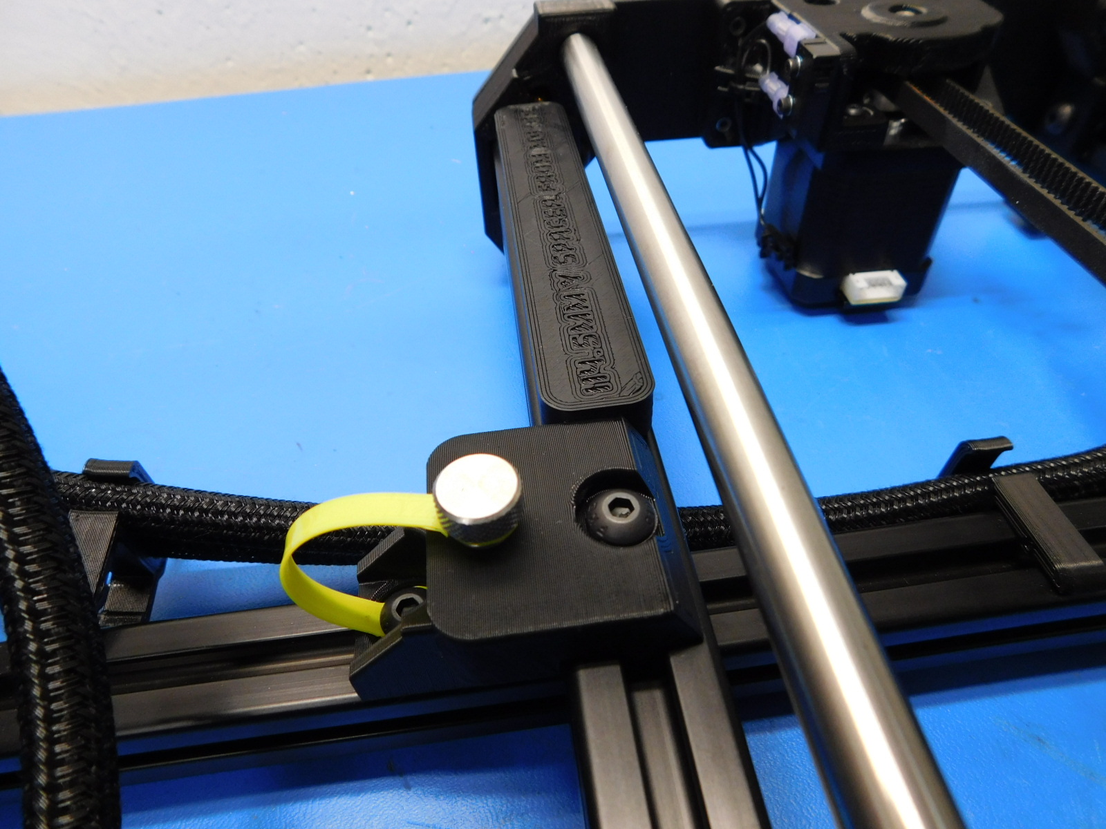
Install one M5 Thumb Screw [HD-MS0554] through each table mount, into the insert in the Chassis mounts.
Tighten securely by hand.


Place the Y-Axis rear spacer (printed jig) on the top rear of the left Y-Axis frame extrusion between the Y-Corner and the Y-Table Mount, as pictured.
Slide the Y-Axis frame forward so that the spacer jig cannot be wiggled back and forth.
Tighten the fastener securing the left table mounts to the y-axis frame.
Torque to 5in*lbs
Place the pre-cut Y-Frame square at the location shown.
Move the right Y-Axis frame forward or back slightly until it is square; you should not be able to wiggle the square and there should be no gaps.
Tighten the right chassis mount and table mount fasteners.
Torque to 5in*lbs
Double check with the square to ensure proper alignment.


Connect the 3-pin connector at the Y-Motor to the 3-pin connector on the Y-Motor Harness.
Connect the JST of the Y-Motor Harness to the Y-Motor.
Using a ball-tipped 4mm hex driver through the hole in the Y Cable Cover, attach the Y Cable Mount to the bed plate.
Tighten securely.
Connect the 3-pin connector underneath the bed plate.


Due to similar appearance, you must first verify that you have the correct extruder to mount.
The Workhorse Edition Tool Head has used two different nozzle types. The hardened steel nozzle and the plated copper nozzle. These can be differentiated by their color.
Hardened steel nozzles will be darker and dull in appearance, see images.
The sticker on the blower shroud should read "HE 0.5mm"
Printers with a serial number earlier than KT-PR0051NA-2705 will have used the hardened steel, and all subsequent printers will have the the plated copper nozzles installed.
The WE Tool Head also includes a black Idler Tube Clamp, verify that it is present and installed correctly.


Obtain one complete Tool Head Assembly [AS-TH0076]
Attach the Tool Head Assembly [AS-TH0076] to the X-Carriage using one Blue M3x50 [HD-BT0222] from the rear of the X-Carriage, and two Blue M3x16 [HD-BT0223] from the top of the X-Carriage.
Torque to 5in*lbs
Connect the tool head connector to the extruder harness.


Move each axis through the entire range of motion while observing where the belt rides in each idler. The belt should not rub on any printed or machined parts.
The position of the Z axis belt in the idlers can be adjusted by use of the 2 set screws in the Z-Top plates behind and in front of the Z belt tension screw. If the belt is riding towards the front, tighten the set screw in front of the Z belt tension screw. If riding towards the rear, tighten the rear set screw.
X belt position can be slightly corrected by tightening one of the X belt tensioner screws tighter than the other and thus securing the belt at an angle; If riding towards the front, tighten the rear tensioner screw further than the front. If riding towards the rear, tighten the front tensioner screw further than the rear.


Final Assembly is now complete, check your work.
Place the completed final assembly on the rack of completed finals to be calibrated.
