Open HardwareAssembly Instructions
Guides for installation and assembly of the LulzBot line of products made by FAME 3D LLC.
Guides for installation and assembly of the LulzBot line of products made by FAME 3D LLC.
1x- [PP-GP0435] Flexy LCD Knob
2x- [HD-MS0336] Black Adhesive-Back Bumper, Square
1x- Control Box Assembly - untested
1x- Control Box Test Stand

Before testing can begin, firmware must be uploaded to the Control Box via the USB port on the rear of the chassis.
Connect a North American Power Cable to the receptacle located on the bottom rear of the chassis.
Connect the USB Cable from the Workstation Computer to the USB port on the rear of the chassis.
Power on the Control Box
Open CuraLE From the top menu bar select settings > printer > manage printers Make sure "LULZBOT TAZ Workhorse Edition Dualv3" is selected from the list of printers. Add it if needed. From the menu, select "Upgrade Firmware"
From the resulting dialogue, select "Upload Custom Firmware".
Navigate to "~/devel/lulzbot/software/marlin/2.0.0.144/" and select "Marlin_TAZWorkhorse_DualExtruderV3_2.0.0.144_aded3b617.hex"
Once the firmware upload is complete the unit will reboot and is now ready for testing.


Place the flashed unit to be tested to the left of the Control Box Test Stand
  | Extruder
  |
  | X motor
  | X Min
  |
  | Bed Thermistor
  | Bed Ground
  | Bed Power
  |
  | Z max
  | Z left motor
  | Y Motor
  | Y Endstop
  | Z right motor
  | Ground
Connect all of the external connectors of the Control Box to the Control Box Test Stand:
Extruder Connector – 20 pin Molex Microfit connector
Z Motors – JST connectors; one short one long from bottom of interconnect
X Motor – JST connector; second harness exiting from top of interconnect
X Endstop - 2 purple Quick Connects at the end of the X Harness
Y Motor – JST connector; middle length of 3 cables at bottom of interconnect
Y Endstop - 3 pin connector at end of Y Motor Harness
Bed Power – Anderson connector
Bed Ground – 3 pin Molex SL connector
Bed Thermistor – 2 pin Molex SL connector
Z Max – 2 pin Molex SL connector located at interconnect housing
Ground - clip gator clip to Hi-Pot testing screw at bottom of interconnect housing


Install one Flexy Knob [PP-GP0435] onto the encoder knob of the LCD screen.
Press firmly.

Begin by powering on the connected unit to be tested and the Control Box Test Stand
The following checks must be performed BEFORE starting the test gcode:
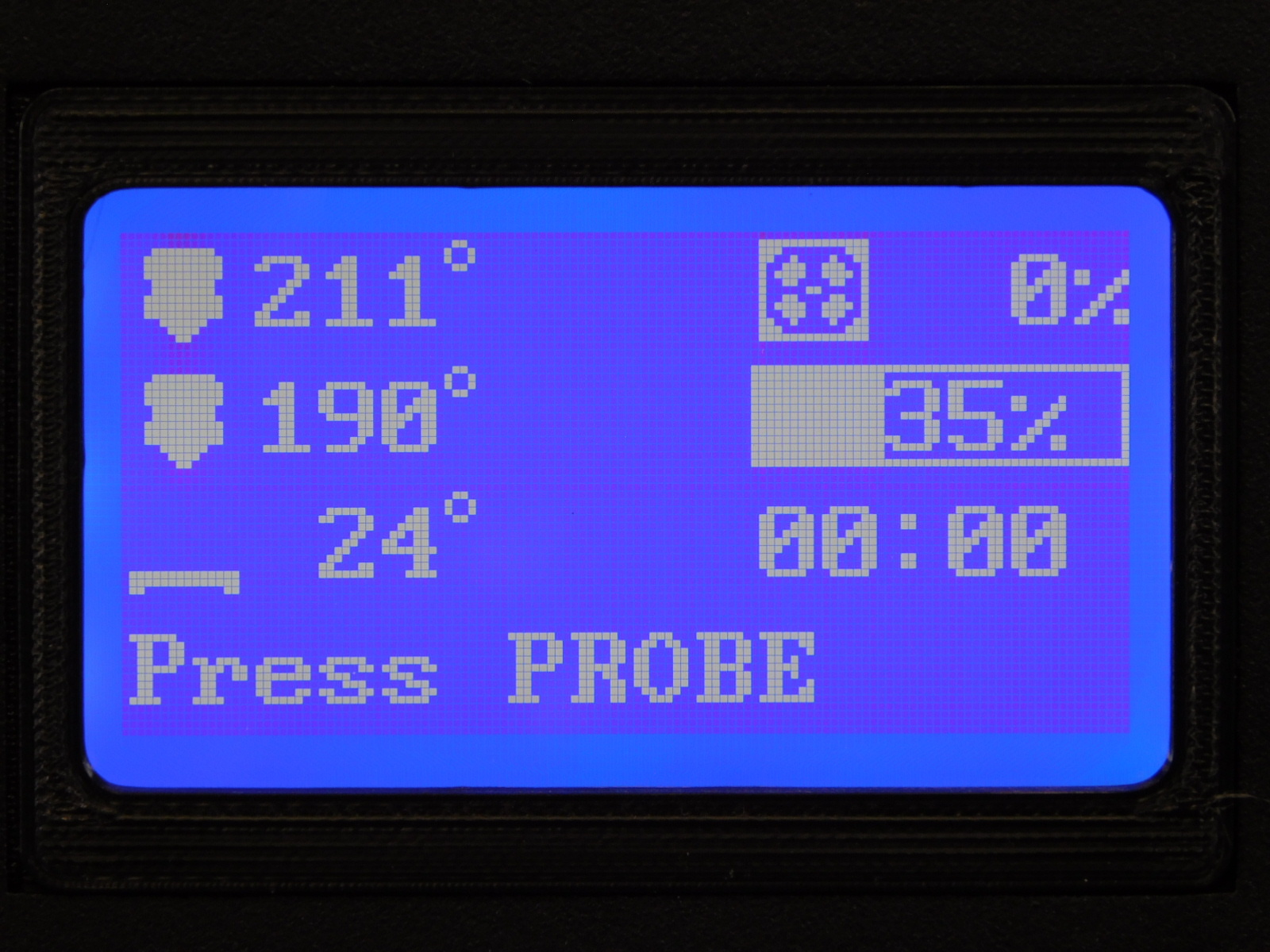
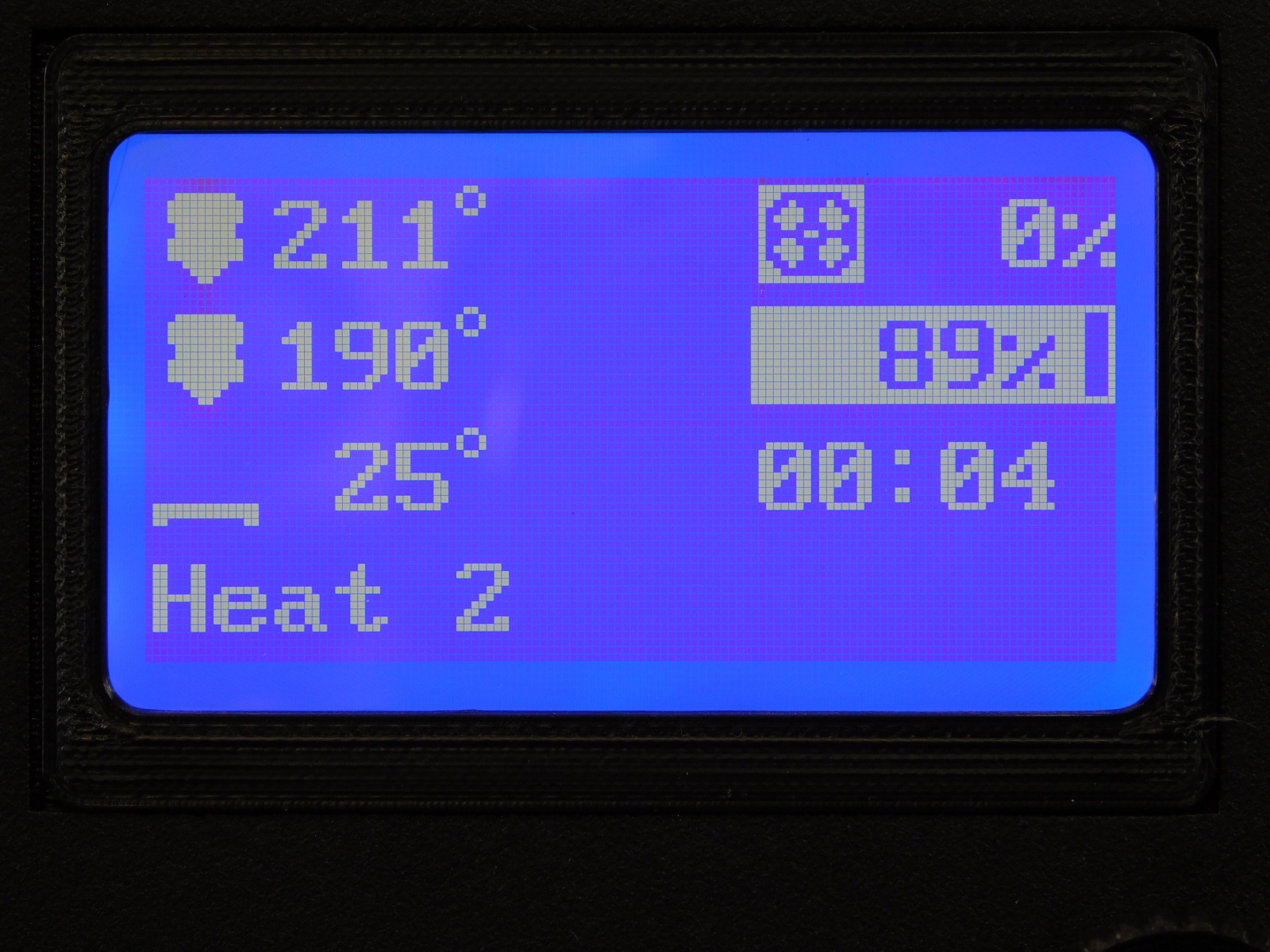
1. Check thermistor values:
Hot End 1 should read 211C
Hot End 2 should read 190C
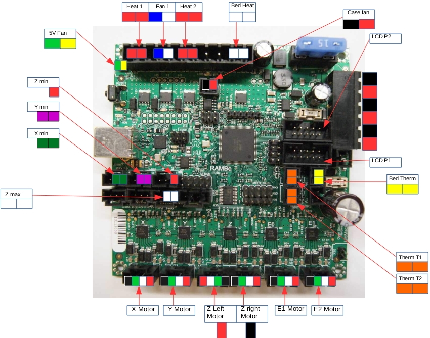
If the values listed above are reversed or no value is shown (0) the unit has failed testing and must be reworked. In this case, the two thermistor connectors inside the unit are connected incorrectly. Return the unit to an ESD safe work area, remove the Electronics Cover, and verify correct connector locations. See Pinout Diagram
2. Check bed thermistor value:
Should read close to room temperature in degrees C, if no value is shown, verify external connection before returning the unit to an ESD safe work area for rework.
3. Check 5v Heat Sink Fan:
The heat sink fan (labeled 5v and located on bottom panel of CB Test Stand) should be spinning any time the unit is powered on. If either of these fans is not functioning the unit has failed the test and must be reworked. After returning the unit to an ESD Safe work area and removing the cover, verify the tool head power connector is pinned correctly and properly connected. See Pinout Diagram
4. Case Fan:
Verify that the case fan is blowing air OUT from the rear of the case. A sticky note or other small piece of paper may be used to verify direction of flow.


If the unit passed the above checks, insert the preloaded SD Card to the slot on the left side of the chassis.
Before proceeding, familiarize yourself with steps 6 thru 8
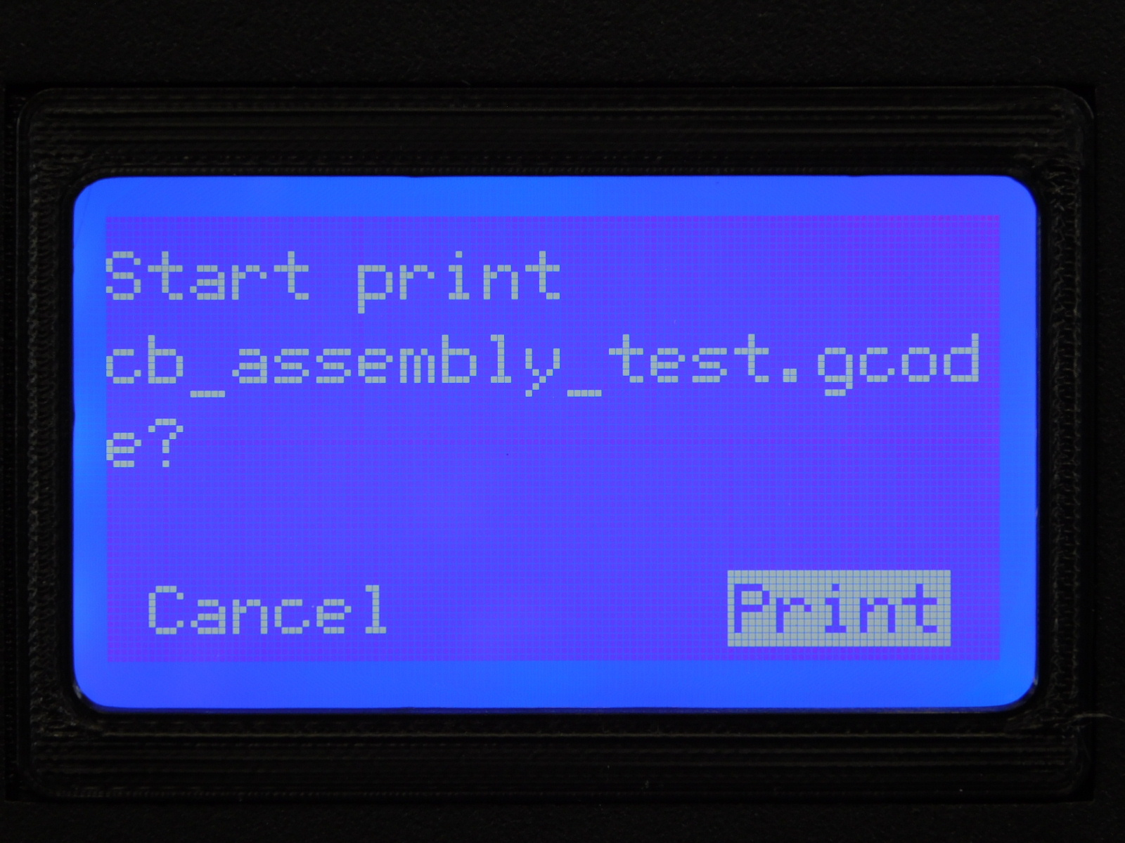
Press the LCD Knob to enter the Menu, scroll to the bottom and select Print from SD Select cb_assembly_test.gcode Select Print


After selecting “Print” the unit will begin the test gcode by homing the X axis, the motor should begin by spinning counter-clockwise.
Press and release the X-Min button on the left of the CB Test Stand to trigger the endstop.
The X Motor should now slowly turn clockwise
Failure conditions:
If the X Motor moves clockwise first, the motor is wired incorrectly.
If the motor fails to move at all, check external connections first.
If the X Motor jiggles or twitches, this is indicative of poor connection on one of the individual wires of the motor lead.
In the event that the above failures occur and are not rectified by checking connections, return the unit to an ESD Safe work space for diagnosis and repair.


The Y Motor will begin moving counter-clockwise immediately following the X Motor’s clockwise move.
Press and release the Y-Min button on the left side of the CB Test Stand to trigger the end stop.
The Y Motor should now spin slowly clockwise.
Failure conditions:
If the Y Motor moves clockwise first, the motor is wired incorrectly.
If the motor fails to move at all, check external connections first.
If the Y Motor jiggles or twitches, this is indicative of poor connection on one of the individual wires of the motor lead.
In the event that the above failures occur and are not rectified by checking connections, return the unit to an ESD Safe workspace for diagnosis and repair.


The Z Motors will now begin moving simultaneously, the left one turning counter-clockwise and the right turning clockwise.
Press and release the Z-Max button on the left side of the CB Test Stand
This emulates the Z Max switch on the printer.
The motors should now spin the opposite direction.
Failure conditions:
If the Z Left Motor moves clockwise first, the motor is wired incorrectly.
If the Z Right motor moves counter-clockwise first, the motor is wired incorrectly.
If the motor fails to move at all, check external connections first.
If the Z Motors jiggle or twitch, this is indicative of poor connection on one of the individual wires of the motor leads.
In the event that the above failures occur and are not rectified by checking connections, return the unit to an ESD Safe work space for diagnosis and repair.


The unit will now wait indefinitely for the user to press the Probe button on the left side of the CB Test Stand.
Now is a good time to read ahead if you haven’t already, so that you’re aware of the conditions that must be visually verified from this point forward.
Press and release the Probe button.
Failure condition:
If the unit does not proceed with the test following actuation of the probe button, there is not continuity in the circuit and the unit has failed the test.
Check external connections to the CB Test Stand and reattempt before returning the unit to an ESD Safe workspace for diagnosis and rework.

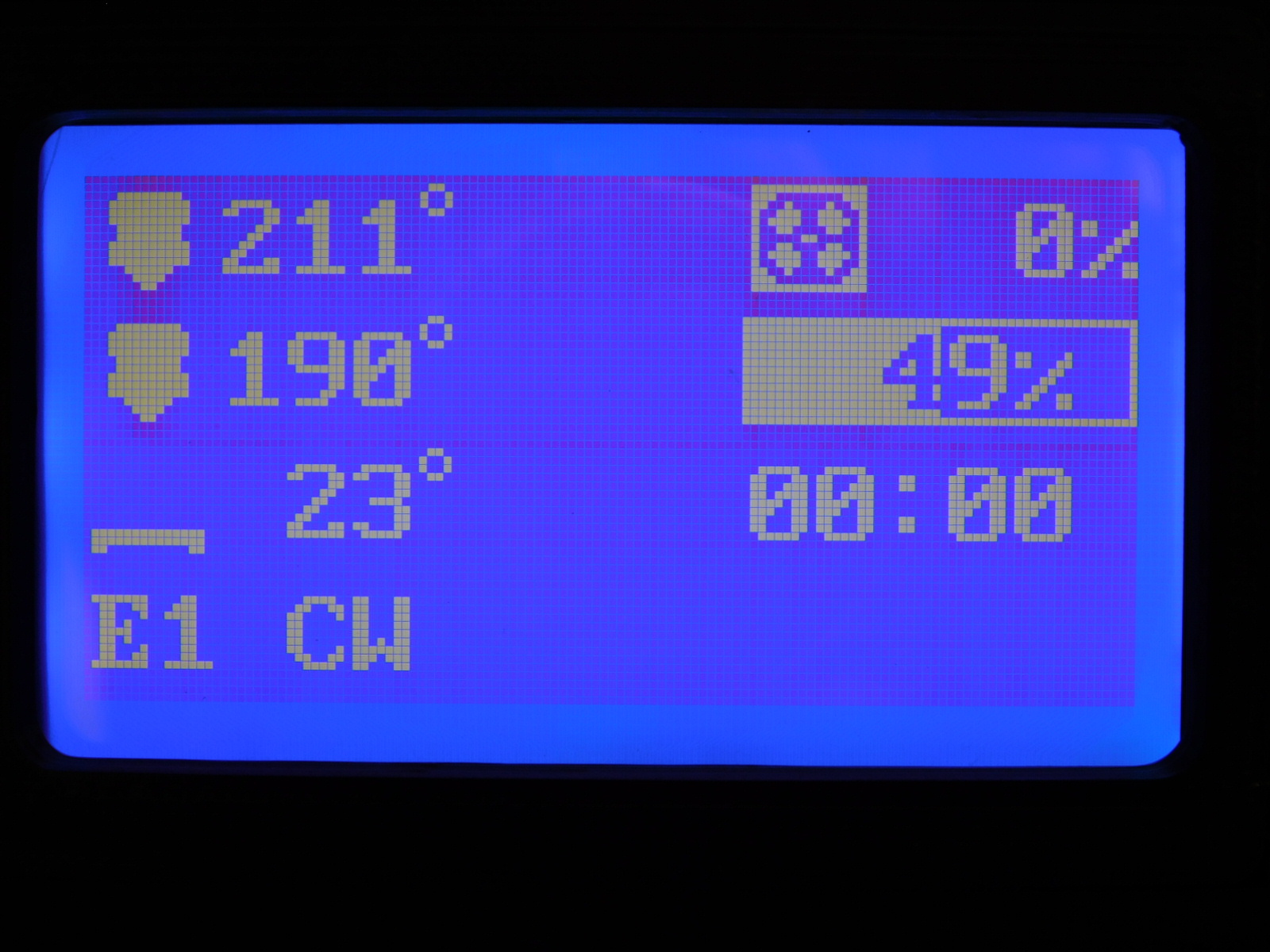
Immediately following actuation of the probe button, the E1 Motor on the test stand should begin moving counter-clockwise.
If the motor moved clockwise first or failed to move it is not wired correctly and the unit has failed the test.
To confirm the motor moved counter-clockwise and proceed with the test, press the PROBE button.
The motor will now spin clockwise.
To confirm and proceed with the test press the PROBE button.


The E2 motor will now move clockwise.
If the motor moved counter-clockwise first or failed to move it is not wired correctly and the unit has failed the test.
To confirm the motor moved clockwise and proceed with the test, press the PROBE button.
The motor will now spin counter-clockwise.
To confirm and proceed with the test press the PROBE button.


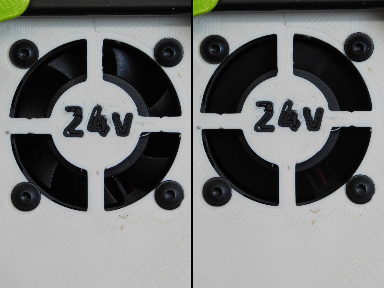
The 24v fan on the CB Test Stand should now be spinning at 40%, it will then speed up to 100%
If the fan doesn’t turn on, the unit has failed the test. Check external connections to the CB Test Stand before returning the unit to an ESD Safe work area for diagnosis and rework.


The fan on the right panel of the CB Test Stand labeled ”H-E1” should now turn on.
If the fan did not turn on the unit has failed the test and should be returned to an ESD Safe workspace for diagnosis and repair.


The fan on the right panel of the CB Test Stand labeled ”H-E2” should now turn on.
If the fan did not turn on the unit has failed the test and should be returned to an ESD Safe workspace for diagnosis and repair.

The fan on the right panel of the CB Test Stand labeled ”BED” should now turn on.
If the fan did not turn on the unit has failed the test and should be returned to an ESD Safe workspace for diagnosis and repair.


Ensure the assembly is connected to a workstation computer via USB and powered on.
Make sure "TAZ Workhorse | HE | 0.5mm" is selected from the list of printers. Add it if needed.
From the top menu bar select settings > printer > manage printers
From the menu, select "Upgrade Firmware" From the resulting dialogue, select "Upload custom firmware".
Navigate to and select "Marlin_TAZWorkhorse_HardenedExtruder_2.0.0.144_aded3b617.hex" then select "Open"
Once CuraLE has finished writing the firmware to the RAMBo, all open dialogues can be closed.
Power off and disconnect the unit from all connections.


Power off the unit
Carefully disconnect the unit from the test stand
Lay the assembly down on a clean surface
Install two rubber feet [HD-MS0363] to the bottom of the chassis at the corners shown.
For transit between work areas:
Wrap the whole thing in bubble wrap and place it on the cart of passed tested units.
Nicely done!

